US7771047B2 - Error-tolerant progressive glass design - Google Patents
Error-tolerant progressive glass design Download PDFInfo
- Publication number
- US7771047B2 US7771047B2 US10/569,952 US56995204A US7771047B2 US 7771047 B2 US7771047 B2 US 7771047B2 US 56995204 A US56995204 A US 56995204A US 7771047 B2 US7771047 B2 US 7771047B2
- Authority
- US
- United States
- Prior art keywords
- dpt
- reference point
- value
- progressive lens
- far
- Prior art date
- Legal status (The legal status is an assumption and is not a legal conclusion. Google has not performed a legal analysis and makes no representation as to the accuracy of the status listed.)
- Active, expires
Links
Images


Classifications
-
- G—PHYSICS
- G02—OPTICS
- G02C—SPECTACLES; SUNGLASSES OR GOGGLES INSOFAR AS THEY HAVE THE SAME FEATURES AS SPECTACLES; CONTACT LENSES
- G02C7/00—Optical parts
- G02C7/02—Lenses; Lens systems ; Methods of designing lenses
- G02C7/06—Lenses; Lens systems ; Methods of designing lenses bifocal; multifocal ; progressive
- G02C7/061—Spectacle lenses with progressively varying focal power
-
- G—PHYSICS
- G02—OPTICS
- G02C—SPECTACLES; SUNGLASSES OR GOGGLES INSOFAR AS THEY HAVE THE SAME FEATURES AS SPECTACLES; CONTACT LENSES
- G02C7/00—Optical parts
- G02C7/02—Lenses; Lens systems ; Methods of designing lenses
- G02C7/024—Methods of designing ophthalmic lenses
- G02C7/027—Methods of designing ophthalmic lenses considering wearer's parameters
Definitions
- the invention relates to a method of producing a progressive spectacle glass as well as to a corresponding progressive spectacle glass.
- Progressive spectacle glasses are distinguished by the fact that they have an area for looking into the distance called a far focusing range and an area for seeing nearby called a near focusing range, these areas being connected with one another by a so-called progression zone.
- the effect of the spectacle lens increases from the value of the far reference point B F to the value of the near reference point B N situated in the near area along a helical line which is called the main line.
- the effect difference between the far and the near reference point is called addition.
- the far focusing range is arranged in the upper area and the near focusing range is arranged in the lower area of the usage position of the spectacle lens.
- Such progressive spectacle glasses are well known in the state of the art. Only as an example, reference is made to International Patent Application WO 01/81981 of Rodenstock GmbH, Ober.
- such progressive eye glasses have, in addition to the initially mentioned far and near reference point, a prism reference point and a centering point.
- the far reference point B F the far focusing effect, that is, the spherical and/or cylindrical effect of the spectacle glass, is reached.
- the near reference point B N the near effect, that is, the far effect plus the addition, is reached.
- the prismatic effect that is, the prescribed prism and the thickness reduction prism, is reached.
- the centering point B Z is used for centering the spectacle glass and thus represents that point which defines the local position of the spectacle glass with respect to the eye.
- a progressive spectacle glass is centered in front of the eye such that, when the position of the head and body is normal, the spectacle glass, in the case of the so-called zero viewing direction (that is, when the viewing is horizontal), is positioned in front of the eye such that the centering point is situated in front of the pupillary center of the eye.
- the so-called horizontal line H of the glass is used as the zero point, the spatial position and direction of the horizontal line H usually being defined by permanent markings which are typically situated at a distance of 17 mm laterally of the main meridian.
- the glass center In the center between the permanent markings on the horizontal line of the glass, the glass center is situated, which in most cases (glasses not predecentered) is the geometrical center of the surface of the unframed glass. In this case, the glass center point coincides with the prism reference point.
- the human eye only has a small aperture which varies between 2 and 7 mm.
- the human visual system has also superimposed a “sensory aperture” on the physical aperture.
- This phenomenon which is known as the Stiles-Crawford effect, is caused in that the cones—like optical waveguides—are oriented to the pupillary center and are therefore clearly more sensitive to rays coming from there. This results in an effective opening of the pupil of only 2 to 5 mm.
- the negative desired refraction deviation is preferably between 0.08 dpt and 0.12 dpt.
- the calculation of the progressive spectacle glass is therefore not based on the ordering value of the average use value in the far reference point B F , but on a so-called calculation value which, with respect to the ordering value, has a negative desired fraction deviation.
- the calculation and optimization of the progressive spectacle glass does not start with the ordering value of the average use value in the far reference point B F prescribed for the wearer of the spectacles but a calculation value which deviates therefrom and which is reduced by a predetermined desired refraction deviation with respect to the ordering value.
- the calculation and optimization step therefore takes place on the basis of an average use value in the far reference point B F which does not correspond to the prescribed median use value.
- the average use value D in the sense of this invention, is the average value of the reciprocal values of the image-side distances S′ 1 and S′ 2 (between the back lens and the image minus the object distance, thus the object-side distance S, wherein the following applies:
- the calculation value on which the calculation or optimization is based is reduced with respect to the ordering value of the refractive power in the use position in the far reference point B F of the progressive spectacle glass by a predetermined negative desired refraction deviation between 0.03 dpt and 0.2 dpt.
- the calculation or optimization step is based on a calculation value of the average use value which nominally for the ordering wearer of the spectacles has a negative desired refraction error of a predetermined amount.
- the refraction value distribution, on which the calculation and optimization step is based may, for example, be as in International Patent Document WO 01/81981.
- the step of calculating the progressive lens or spectacle glass takes place by taking into account a calculation addition which is increased at least by the amount of the negative desired refraction deviation in the far reference point in comparison with the ordering addition.
- the average use value (or the refraction value in the use position) in the near reference point B N is, for example, equal to the prescribed or ordered average use value in the near reference point B N .
- the calculation addition on which the calculation step is based is increased by that amount by which the effect in the far reference point was nominally reduced.
- the calculation addition is increased with respect to the ordering addition by the sum
- the calculation step of the progressive spectacle glass takes place on the basis of (calculation) refraction values in the use position, which differ in the far reference point as well as in the near reference point from the prescribed (ordering) values.
- the ordering values in the far reference point there is nominally a negative refraction deviation and, in the near reference point, there is nominally a positive refraction deviation.
- the step of calculating the progressive spectacle glass or lens while taking into account a predetermined desired refraction error takes place on the main line as a function of the y-coordinate along the vertical section of the spectacle glass.
- the calculation of the progressive spectacle glass takes place while considering a predetermined desired refraction error along the main line or of the main meridian of the spectacle glass, the desired refraction error being a function of y (that is, of the vertical axis).
- the predetermined desired refraction error is preferably set such that, in the far reference point, for the calculation value of the average use value, a negative desired refraction deviation is obtained with respect to the corresponding ordering value and, in the near reference point, a positive desired refraction deviation of the calculation value is obtained with respect to the corresponding ordering value.
- a so-called double asymptotic function for the desired refraction error is used as a function of y of the form:
- f ⁇ ( y ) b + a ⁇ a 1 + 3 c ⁇ ( y + d ) ⁇ m + ⁇ i ⁇ ⁇ giy i
- a, b, c, d, m and g 1 are constants.
- cubical or higher-grade spline functions or other suitable functions may be used.
- the step of calculating the progressive spectacle glass preferably takes place such that the average use value of the produced spectacle glass increases as little as possible in the case of a horizontal viewing deflection in the far range.
- the average use value of the produced spectacle glass at the height of the far reference point in the case of a horizontal viewing deflection preferably increases by less than 0.25 dpt, preferably by less than 0.15 dpt, in comparison to the average use value in the far reference point.
- the calculation step can be implemented such that, when an (additional) refraction error of +0.2 dpt is superimposed (for example, because of manufacturing fluctuations), the far range is reduced by not more than 5%, preferably by not more than 3%.
- a progressive spectacle glass which has a far vision part with a far reference point, a near vision part and a progression zone, the progressive spectacle glass being designed such that its calculation takes place while taking into account a calculation value of the average use value in the far reference point, the calculation value having a negative desired refraction deviation of between 0.03 dpt and 0.2 dpt with respect to a predefined ordering value of the average use value in the far reference point.
- the negative refraction deviation is preferably between 0.08 dpt and 0.12 dpt.
- the progressive spectacle glass is preferably designed such that its calculation takes place while taking into account a calculation addition which is increased at least by the amount of the negative desired refraction deviation in the far reference point in comparison to the ordering addition.
- the calculation addition is preferably increased with respect to the ordering addition by the sum
- a progressive spectacle glass which has a far vision part, a near vision part and a progression zone, the progressive spectacle glass being designed such that, when a refraction error of +0.2 dpt is superimposed, the far range is reduced by not more than 5%, preferably by not more than 3%.
- FIG. 1 a is a view of the refraction value distribution of a conventional progressive spectacle glass
- FIG. 1 b is a similar distribution view but of a preferred lens produced according to the invention, each in the use position;
- FIG. 2 a is a view of the astigmatism distribution of the conventional progressive spectacle glass
- FIG. 2 b is a similar distribution view but of the preferred spectacle lens produced according to the invention of the spectacle lens also illustrated in FIGS. 1 a and 1 b , each in the use position;
- FIG. 3 a is a view of the distribution of the relative reduction of the visual acuity as a result of the imaging errors (astigmatic deviation and refractive deviation) of the conventional progressive spectacle lens
- FIG. 3 a is a similar distribution view of the preferred progressive spectacle lens according to the invention.
- FIG. 4 a is a view of the distribution of the relative reduction of the visual acuity as a result of the imaging errors of the conventional progressive spectacle glass
- FIG. 4 b is a similar distribution view of the preferred progressive spectacle glass according to the invention when an additional refraction error of ⁇ 0.2 dpt occurs;
- FIG. 5 a is a view of the distribution of the relative reduction of the visual acuity as a result of the imaging errors of the conventional spectacle lens
- FIG. 5 b is a similar distribution view of the preferred progressive spectacle lens according to the invention when an additional refraction error of +0.2 dpt occurs;
- FIG. 6 a is a view of the cambers of the preferred spectacle glass of the invention according to FIGS. 1 b to 5 b;
- FIG. 6 b is a view of the average surface refraction value of the preferred spectacle glass of the invention according to FIGS. 1 b to 5 b;
- FIG. 6 c is a view of the surface astigmatism of the preferred spectacle glass of the invention according to FIGS. 1 b to 5 b;
- the calculation and optimization step of the progressive spectacle glass takes place on the basis of calculation values for the average use value in the far reference point and the near reference point which each differ in a targeted manner from the corresponding ordering values or prescribed values.
- the calculation value for the refraction value in the use position in the far reference point is reduced by a predetermined negative desired refraction deviation with respect to the corresponding ordering value, and the calculation addition on which the calculation is based is increased by at least the same amount with respect to the prescribed addition (ordering addition).
- the calculation addition is even increased such with respect to the ordering addition that the calculation of the progressive spectacle glass is based on a positive desired refraction deviation of the refraction value in the use position in the near reference point in comparison to the corresponding ordering refraction value.
- a progressive spectacle glass is surprisingly obtained which regularly has improved optical characteristics for the wearer of the spectacles and particularly a lower sensitivity with respect to small additional refraction deviations.
- the invention is based on the recognition, which is known per se, that, in the use position (or the average use value) of a progressive spectacle glass depends on the opening of the pupil of the seeing eye. This basic relationship is illustrated in the manner of examples in Tables 1 to 3.
- Table 1 shows the refraction value in the use position in the far reference point B F , the centering point B Z and the near reference point B N for the addition Add 1.0, 2.0 and 3.0 dpt and the spherical effects Sph ⁇ 4.0, ⁇ 1.0, 2.0 and 5.0 dpt with an infinitesimal opening of the pupil for a conventional progressive spectacle glass.
- the spherical effect Sph in the lines of the table and the additions Add in the columns of the table are constant.
- Table 2 shows the refraction value in the use position in the indicated reference points for the additions Add 1.0, 2.0 and 3.0 dpt and the spherical effects Sph ⁇ 1.0 and 2.0 dpt in the case of a pupil opening of 3.5 mm.
- Table 3 finally shows the refraction value in the use position in the mentioned reference points for the additions 1.0, 2.0 and 3.0 and the spherical effects ⁇ 4.0, ⁇ 1.0, 2.0 and 5.0 with a pupil opening of 6 mm.
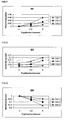
- FIGS. 7 to 12 illustrate the deviation of the refraction value in the use position as a function of the diameter of the pupil of the seeing eye for different additions in the respectively indicated reference points with the given spherical effect.
- the spherical effect amounts to ⁇ 1.0 dpt and the indicated additions Add—as illustrated in the respective insets—amount to ⁇ 1, 2 and 3 dpt.
- FIG. 7 shows the dependence of the deviation of the refraction value in the use position on the pupil diameter in the far reference point B F ;
- FIG. 8 shows this in the centering point B Z ;
- FIG. 9 in the near reference point B N .
- FIGS. 10 to 12 correspond to the respective FIGS. 7 to 9 in all corresponding values, with the exception of the spherical effect, which in each case amounts to +2.0 dpt in FIGS. 10 to 12 .
- the invention counteracts such a negative influence in that, in the calculation process of the progressive spectacle glass, a negative desired refraction deviation is introduced in the far reference point and a positive desired refraction deviation is introduced in the near reference point.
- a desired refraction deviation introduced in a targeted manner has the result that a correspondingly produced progressive spectacle glass has significantly improved optical imaging characteristics for the wearer of the spectacles also in the case of large openings of the pupil.
- the invention is also based on the recognition that positive refraction errors (fogginess) have a far more critical effect on the optical imaging characteristics than negative refraction errors.
- the cause is that positive errors can be compensated only by the depth of focus. However, the depth of focus decreases considerably with the increase of the opening of the pupil.
- the invention applies the recognition that positive errors are not only more critical but also occur more frequently.
- the cause is particularly the refraction determination for determining the prescription or ordering values.
- the refraction determination is carried out in a room with a vision test distance of from 5 to 6 m. Because of the fact that the vision test is not in infinity but at a finite distance, a positive refraction occurs of approximately 0.15 to 0.2 dpt. Although a complete refraction determination contains the examination with respect to infinity, often or as a rule, this is not carried out and this error therefore remains.
- a progressive spectacle glass can be produced which nominally in the far reference point has a negative refraction error and in the near reference point has a positive reaction error. This, on the one hand, takes into account the refraction value increase and decrease when the opening of the pupil is enlarged and, on the other hand, the design becomes less sensitive to small refraction deviations.
- FIG. 1 a shows the refraction value distribution
- FIG. 2 a shows the astigmatism distribution of a conventional progressive spectacle glass or lens in each case in the use position.
- the spectacle glass is a progressive spectacle glass of Rodenstock GmbH, which is sold under the tradename Multigressiv ILT.
- FIGS. 1 b and 2 b correspondingly show a preferred spectacle glass or lens according to the invention with a changed refraction value distribution and superimposed negative and positive desired refraction errors in the reference points.
- a negative desired refraction deviation of 0.1 dpt was introduced into the far reference point which in FIG. 1 b is outlined by an upper circle on the helical main line. Simultaneously the calculation addition was increased by 0.1 dpt with respect to the ordering addition.
- the near reference point is characterized by a lower circle on the main line.
- the conventional spectacle lens as well as the spectacle lens according to the invention have a spherical (ordering) far effect of 0.50 dpt and an (ordering) addition of 2.00 dpt.
- FIG. 1 b illustrates that the refraction value in the far reference point is smaller in comparison to the conventional spectacle glass according to FIG. 1 a .
- the slightly higher addition in the case of the invention causes a slightly narrower progression range in comparison to the conventional spectacle glass according to FIG. 1 a . This disadvantage cannot be prevented.
- FIGS. 3 a (conventional spectacle glass) and 3 b (preferred spectacle glass according to the invention) each show the distribution of the relative reduction of the visual acuity as a result of imaging errors (astigmatic deviation and refraction deviation) of the progressive spectacle glasses illustrated in FIGS. 1 a and 1 b , respectively and FIGS. 2 a and 2 b , respectively.
- the relative reduction of the visual acuity of a wearer of the spectacles indicates how much the spectacle wearer's visual acuity is reduced by the imaging errors (astigmatic error and refraction error) of the spectacle glass.
- 3 a to 5 b with, for example, 0.9 means that the visual acuity is reduced to 90% of the spectacle wearer's initial sight.
- a spectacle wearer with a fully corrected spectacle glass has a visual acuity (sight) of 1.6
- his sight when looking through the spectacle glass at a point at which the visual acuity reduction amounts to 0.9 will only still be 0.9*1.6, that is, 1.44.
- FIGS. 4 a and 4 b each show the distribution of the relative reduction of visual acuity when an additional negative refraction error of ⁇ 0.2 dpt occurs in the case of the progressive spectacle glass illustrated in FIGS. 3 a and 3 b .
- Virtually no differences can be seen with respect to the optimal correction according to FIGS. 3 a and 3 b . Because of the existing residual accommodation capacity, these errors can be compensated.
- FIGS. 5 a and 5 b each show the distribution of the relative reduction of the visual acuity when an additional positive refraction error of +0.2 dpt occurs in the case of the progressive spectacle glasses illustrated in FIGS. 3 a and 3 b .
- FIG. 5 b shows the insensitivity of the spectacle glass according to the invention with respect to small positive refraction errors. While, in the case of the conventional spectacle glass of FIG. 5 a , the far range is clearly reduced, it remains almost unchanged in the case of the spectacle glass according to the invention. In this case, the far range is defined as the range within a semicircle with a radius of 20 mm about a point which is situated 4 mm below the centering point (illustrated by a cross in FIGS. 5 a and 5 b ), and above a horizontal line which extends through this point and whose relative visual acuity amounts to more than 0.9 dpt.
- FIGS. 2 a , 2 b , 3 a and 3 b already show that the progression range becomes slightly smaller as a result of the addition increase.
- the additional refraction error for example, because of manufacturing fluctuations—the “reverse case” may also occur.
- the refraction determination can in fact be carried out for infinite vision test distances, but subsequently the spectacle glass can be used only in a closed space. In this case, the spectacle glass already has a negative refraction error of 0.1 to 0.2 dpt in the distance, and 0.12 dpt may be added again because of measuring inaccuracies.
- the introduced desired refraction superimposition should therefore be between 0.03 and 0.2 dpt, preferably between 0.08 and 0.12 dpt, in the far reference point.
- FIGS. 6 a, b and c show the cambers, the average surface refraction value and the surface astigmatism of the above-described preferred spectacle glass according to the invention.
Landscapes
- Health & Medical Sciences (AREA)
- Ophthalmology & Optometry (AREA)
- Physics & Mathematics (AREA)
- General Health & Medical Sciences (AREA)
- General Physics & Mathematics (AREA)
- Optics & Photonics (AREA)
- Eyeglasses (AREA)
Applications Claiming Priority (4)
| Application Number | Priority Date | Filing Date | Title |
|---|---|---|---|
| DE10339948A DE10339948A1 (de) | 2003-08-29 | 2003-08-29 | Fehlertolerantes Progressivglasdesign |
| DE10339948 | 2003-08-29 | ||
| DE103-39.948.8 | 2003-08-29 | ||
| PCT/EP2004/009227 WO2005029160A1 (fr) | 2003-08-29 | 2004-08-17 | Conception de verre progressif a tolerance d'erreur |
Publications (2)
| Publication Number | Publication Date |
|---|---|
| US20070109496A1 US20070109496A1 (en) | 2007-05-17 |
| US7771047B2 true US7771047B2 (en) | 2010-08-10 |
Family
ID=34352744
Family Applications (1)
| Application Number | Title | Priority Date | Filing Date |
|---|---|---|---|
| US10/569,952 Active 2026-08-17 US7771047B2 (en) | 2003-08-29 | 2004-08-17 | Error-tolerant progressive glass design |
Country Status (6)
| Country | Link |
|---|---|
| US (1) | US7771047B2 (fr) |
| EP (1) | EP1658522B1 (fr) |
| JP (1) | JP4708344B2 (fr) |
| DE (2) | DE10339948A1 (fr) |
| ES (1) | ES2308220T3 (fr) |
| WO (1) | WO2005029160A1 (fr) |
Families Citing this family (4)
| Publication number | Priority date | Publication date | Assignee | Title |
|---|---|---|---|---|
| DE112008000060A5 (de) * | 2007-01-25 | 2009-12-10 | Rodenstock Gmbh | Verfahren zur Bestimmung der Bezugspunkte Ferne und Nähe |
| EP2115524B1 (fr) | 2007-01-25 | 2018-05-23 | Rodenstock GmbH | Procédé de calcul d'un verre de lunettes à position variable des points de référence |
| JP5989317B2 (ja) * | 2011-09-29 | 2016-09-07 | イーエイチエス レンズ フィリピン インク | 累進屈折力レンズ、その製造方法、およびその設計方法 |
| DE102021000451A1 (de) | 2021-01-29 | 2022-08-04 | Rodenstock Gmbh | System und Verfahren fur die Bestelleingangsverarbeitung und Fertigung von Brillengläsern |
Citations (6)
| Publication number | Priority date | Publication date | Assignee | Title |
|---|---|---|---|---|
| EP0911670A1 (fr) | 1997-10-16 | 1999-04-28 | Essilor International Compagnie Generale D'optique | Lentille ophtalmique multifocale |
| WO2001081981A2 (fr) | 2000-04-25 | 2001-11-01 | Optische Werke G. Rodenstock | Verre de lunettes progressif |
| EP1170620A1 (fr) | 1999-04-13 | 2002-01-09 | Hoya Corporation | Lentille de verres a puissance de refraction progressive et son procede de conception |
| US6412948B2 (en) * | 2000-05-10 | 2002-07-02 | Nikon-Essilor Co., Ltd. | Progressive power multifocal lens |
| US6652096B1 (en) * | 1999-05-31 | 2003-11-25 | Sola International Holdings, Ltd. | Progressive lens |
| US20040032565A1 (en) * | 1999-02-12 | 2004-02-19 | Hoya Corporation | Spectacle lens and manufacturing method therefor |
Family Cites Families (1)
| Publication number | Priority date | Publication date | Assignee | Title |
|---|---|---|---|---|
| EP1410098B1 (fr) * | 2000-01-17 | 2008-09-03 | Rodenstock GmbH | Procede de production de verres progressifs |
-
2003
- 2003-08-29 DE DE10339948A patent/DE10339948A1/de not_active Ceased
-
2004
- 2004-08-17 EP EP04764215A patent/EP1658522B1/fr not_active Expired - Lifetime
- 2004-08-17 DE DE502004007448T patent/DE502004007448D1/de not_active Expired - Lifetime
- 2004-08-17 WO PCT/EP2004/009227 patent/WO2005029160A1/fr active IP Right Grant
- 2004-08-17 US US10/569,952 patent/US7771047B2/en active Active
- 2004-08-17 ES ES04764215T patent/ES2308220T3/es not_active Expired - Lifetime
- 2004-08-17 JP JP2006524293A patent/JP4708344B2/ja not_active Expired - Lifetime
Patent Citations (7)
| Publication number | Priority date | Publication date | Assignee | Title |
|---|---|---|---|---|
| EP0911670A1 (fr) | 1997-10-16 | 1999-04-28 | Essilor International Compagnie Generale D'optique | Lentille ophtalmique multifocale |
| US20040032565A1 (en) * | 1999-02-12 | 2004-02-19 | Hoya Corporation | Spectacle lens and manufacturing method therefor |
| EP1170620A1 (fr) | 1999-04-13 | 2002-01-09 | Hoya Corporation | Lentille de verres a puissance de refraction progressive et son procede de conception |
| US6712467B1 (en) * | 1999-04-13 | 2004-03-30 | Hoya Corporation | Progressive-power lens and design process for same |
| US6652096B1 (en) * | 1999-05-31 | 2003-11-25 | Sola International Holdings, Ltd. | Progressive lens |
| WO2001081981A2 (fr) | 2000-04-25 | 2001-11-01 | Optische Werke G. Rodenstock | Verre de lunettes progressif |
| US6412948B2 (en) * | 2000-05-10 | 2002-07-02 | Nikon-Essilor Co., Ltd. | Progressive power multifocal lens |
Also Published As
| Publication number | Publication date |
|---|---|
| ES2308220T3 (es) | 2008-12-01 |
| EP1658522B1 (fr) | 2008-06-25 |
| EP1658522A1 (fr) | 2006-05-24 |
| JP2007504485A (ja) | 2007-03-01 |
| US20070109496A1 (en) | 2007-05-17 |
| DE502004007448D1 (de) | 2008-08-07 |
| DE10339948A1 (de) | 2005-04-28 |
| JP4708344B2 (ja) | 2011-06-22 |
| WO2005029160A1 (fr) | 2005-03-31 |
Similar Documents
| Publication | Publication Date | Title |
|---|---|---|
| EP2499536B1 (fr) | Élément de lentille ophtalmique | |
| AU729511B2 (en) | Set of progressive multifocal ophthalmic lenses | |
| US9804421B2 (en) | Method for determining at least one optical design parameter for a progressive ophthalmic lens | |
| US20090290121A1 (en) | Method for determining a set of progressive multifocal ophthalmic lenses | |
| US6685316B2 (en) | Method of manufacturing progressive ophthalmic lenses | |
| JP5000505B2 (ja) | 累進屈折力レンズ | |
| EP2367048A1 (fr) | Verre de lunette et son procédé de conception | |
| KR102100726B1 (ko) | 안과용 렌즈의 광학 파라미터 결정 방법 | |
| JP7341131B2 (ja) | 眼科用レンズを評価する方法、眼科用レンズを製造するための関連評価システム及び産業アセンブリ | |
| EP3201683B1 (fr) | Système de distribution de lentille multifocale pour fournir à un utilisateur une lentille ophtalmique de lunettes progressives personnalisées | |
| JP4226903B2 (ja) | 急な屈折力変化をもつ累進多焦点レンズ | |
| US20110080557A1 (en) | Apparatus for measuring downward rotation amount of eyeball and method for measuring downward rotation amount of eyeball | |
| US8646909B2 (en) | Method for determining, optimizing and producing an ophthalmic lens and set of ophthalmic lenses | |
| US7771047B2 (en) | Error-tolerant progressive glass design | |
| EP3362846B1 (fr) | Lentille à addition progressive ophtalmique pour un porteur myope et presbyte ; procédé permettant de fabriquer une telle lentille | |
| RU2768516C1 (ru) | Способ подбора монофокальной офтальмологической линзы | |
| JP5989317B2 (ja) | 累進屈折力レンズ、その製造方法、およびその設計方法 | |
| US20130148078A1 (en) | Progressive multifocal ophthalmic lens | |
| US11067830B2 (en) | Ophthalmic progressive addition lens for a farsighted and presbyopic wearer; method for providing such a lens | |
| US10852565B2 (en) | Ophthalmic progressive addition lens for a myopic and presbyopic wearer and method for providing same | |
| CN107077005B (zh) | 一副眼科镜片的光学设计方法及如此获得的一副眼科镜片 | |
| JP2007504485A5 (fr) | ||
| US10852563B2 (en) | Ophthalmic progressive addition lens for an emmetropic and presbyopic wearer and method of providing same | |
| JP2007509373A (ja) | 特殊な眼鏡レンズ |
Legal Events
| Date | Code | Title | Description |
|---|---|---|---|
| AS | Assignment |
Owner name: RODENSTOCK GMBH,GERMANY Free format text: ASSIGNMENT OF ASSIGNORS INTEREST;ASSIGNORS:ALTHEIMER, HELMUT;ESSER, GREGOR;WELK, ANDREA;AND OTHERS;SIGNING DATES FROM 20060928 TO 20061024;REEL/FRAME:018574/0477 Owner name: RODENSTOCK GMBH, GERMANY Free format text: ASSIGNMENT OF ASSIGNORS INTEREST;ASSIGNORS:ALTHEIMER, HELMUT;ESSER, GREGOR;WELK, ANDREA;AND OTHERS;SIGNING DATES FROM 20060928 TO 20061024;REEL/FRAME:018574/0477 |
|
| STCF | Information on status: patent grant |
Free format text: PATENTED CASE |
|
| FPAY | Fee payment |
Year of fee payment: 4 |
|
| MAFP | Maintenance fee payment |
Free format text: PAYMENT OF MAINTENANCE FEE, 8TH YEAR, LARGE ENTITY (ORIGINAL EVENT CODE: M1552) Year of fee payment: 8 |
|
| MAFP | Maintenance fee payment |
Free format text: PAYMENT OF MAINTENANCE FEE, 12TH YEAR, LARGE ENTITY (ORIGINAL EVENT CODE: M1553); ENTITY STATUS OF PATENT OWNER: LARGE ENTITY Year of fee payment: 12 |