US7754276B2 - Process for manufacturing low ESR conductive polymer based solid electrolytic capacitors - Google Patents
Process for manufacturing low ESR conductive polymer based solid electrolytic capacitors Download PDFInfo
- Publication number
- US7754276B2 US7754276B2 US11/787,378 US78737807A US7754276B2 US 7754276 B2 US7754276 B2 US 7754276B2 US 78737807 A US78737807 A US 78737807A US 7754276 B2 US7754276 B2 US 7754276B2
- Authority
- US
- United States
- Prior art keywords
- forming
- capacitor
- monomer
- monomer solution
- dielectric
- Prior art date
- Legal status (The legal status is an assumption and is not a legal conclusion. Google has not performed a legal analysis and makes no representation as to the accuracy of the status listed.)
- Active, expires
Links
Images


Classifications
-
- H—ELECTRICITY
- H01—ELECTRIC ELEMENTS
- H01G—CAPACITORS; CAPACITORS, RECTIFIERS, DETECTORS, SWITCHING DEVICES OR LIGHT-SENSITIVE DEVICES, OF THE ELECTROLYTIC TYPE
- H01G9/00—Electrolytic capacitors, rectifiers, detectors, switching devices, light-sensitive or temperature-sensitive devices; Processes of their manufacture
- H01G9/0029—Processes of manufacture
- H01G9/0036—Formation of the solid electrolyte layer
-
- H—ELECTRICITY
- H01—ELECTRIC ELEMENTS
- H01G—CAPACITORS; CAPACITORS, RECTIFIERS, DETECTORS, SWITCHING DEVICES OR LIGHT-SENSITIVE DEVICES, OF THE ELECTROLYTIC TYPE
- H01G11/00—Hybrid capacitors, i.e. capacitors having different positive and negative electrodes; Electric double-layer [EDL] capacitors; Processes for the manufacture thereof or of parts thereof
- H01G11/22—Electrodes
- H01G11/30—Electrodes characterised by their material
- H01G11/48—Conductive polymers
-
- H—ELECTRICITY
- H01—ELECTRIC ELEMENTS
- H01G—CAPACITORS; CAPACITORS, RECTIFIERS, DETECTORS, SWITCHING DEVICES OR LIGHT-SENSITIVE DEVICES, OF THE ELECTROLYTIC TYPE
- H01G11/00—Hybrid capacitors, i.e. capacitors having different positive and negative electrodes; Electric double-layer [EDL] capacitors; Processes for the manufacture thereof or of parts thereof
- H01G11/54—Electrolytes
- H01G11/56—Solid electrolytes, e.g. gels; Additives therein
-
- H—ELECTRICITY
- H01—ELECTRIC ELEMENTS
- H01G—CAPACITORS; CAPACITORS, RECTIFIERS, DETECTORS, SWITCHING DEVICES OR LIGHT-SENSITIVE DEVICES, OF THE ELECTROLYTIC TYPE
- H01G11/00—Hybrid capacitors, i.e. capacitors having different positive and negative electrodes; Electric double-layer [EDL] capacitors; Processes for the manufacture thereof or of parts thereof
- H01G11/78—Cases; Housings; Encapsulations; Mountings
- H01G11/82—Fixing or assembling a capacitive element in a housing, e.g. mounting electrodes, current collectors or terminals in containers or encapsulations
-
- H—ELECTRICITY
- H01—ELECTRIC ELEMENTS
- H01G—CAPACITORS; CAPACITORS, RECTIFIERS, DETECTORS, SWITCHING DEVICES OR LIGHT-SENSITIVE DEVICES, OF THE ELECTROLYTIC TYPE
- H01G9/00—Electrolytic capacitors, rectifiers, detectors, switching devices, light-sensitive or temperature-sensitive devices; Processes of their manufacture
- H01G9/004—Details
- H01G9/022—Electrolytes; Absorbents
- H01G9/025—Solid electrolytes
- H01G9/028—Organic semiconducting electrolytes, e.g. TCNQ
-
- H—ELECTRICITY
- H01—ELECTRIC ELEMENTS
- H01G—CAPACITORS; CAPACITORS, RECTIFIERS, DETECTORS, SWITCHING DEVICES OR LIGHT-SENSITIVE DEVICES, OF THE ELECTROLYTIC TYPE
- H01G9/00—Electrolytic capacitors, rectifiers, detectors, switching devices, light-sensitive or temperature-sensitive devices; Processes of their manufacture
- H01G9/15—Solid electrolytic capacitors
-
- Y—GENERAL TAGGING OF NEW TECHNOLOGICAL DEVELOPMENTS; GENERAL TAGGING OF CROSS-SECTIONAL TECHNOLOGIES SPANNING OVER SEVERAL SECTIONS OF THE IPC; TECHNICAL SUBJECTS COVERED BY FORMER USPC CROSS-REFERENCE ART COLLECTIONS [XRACs] AND DIGESTS
- Y02—TECHNOLOGIES OR APPLICATIONS FOR MITIGATION OR ADAPTATION AGAINST CLIMATE CHANGE
- Y02E—REDUCTION OF GREENHOUSE GAS [GHG] EMISSIONS, RELATED TO ENERGY GENERATION, TRANSMISSION OR DISTRIBUTION
- Y02E60/00—Enabling technologies; Technologies with a potential or indirect contribution to GHG emissions mitigation
- Y02E60/13—Energy storage using capacitors
Definitions
- This invention relates to solid electrolytic capacitors having cathodes formed with intrinsically conductive polymers. More specifically, this invention relates to methods for the treatment of monomers of conductive polymers to extend pot life and improve polymer coating performance.
- Solid electrolytic capacitors with conductive polymers as the cathode materials have been widely used in the electronics industry due to their advantageously low equivalent series resistance (ESR) and “non-burning/non-ignition” failure mode.
- Various types of conductive polymers including polypyrrole, polyaniline, and poly(3,4-ethyldioxythiophene) (PEDOT) are applied to electrolytic capacitors as a cathode material when valve metals such as Ta, Al, and Nb as well as conductive oxides such as ceramic NbO, are used as the anode.
- Ta powder for example, is mechanically pressed to form Ta metal pellets, which are subsequently sintered at high temperature under vacuum.
- the sintered pellets are anodized in an electrolyte solution to form a dielectric layer (Ta 2 O 5 ) on the anode surface.
- a conductive polymer such as poly 3,4-ethylenedioxythiophene (PEDOT)
- PEDOT poly 3,4-ethylenedioxythiophene
- an oxidant solution such as iron (III) p-toluenensulfonate solution in a solvent, is first applied onto the anodes.
- the conductive polymer layer should be reasonably robust in order to protect the anodes from potential mechanical damages in the post-polymerization process and from direct contact with carbon and silver layers, which are subsequently applied to provide connection between conductive polymer cathode and the outside circuitry.
- the carbon and silver coated anodes are then encapsulated, aged and tested to complete the manufacturing process.
- An illustrative structure of a conductive polymer based capacitor is illustrated in FIG. 1 .
- the capacitor has an anode, 1 , such as a tantalum anode.
- An anode wire, 2 such as a tantalum wire extends from the anode and is in electrical contact with a leadframe, 8 , such as by a weld, 3 .
- a dielectric is on the surface of the anode. Coated on the surface of the dielectric is a conductive polymer, 5 .
- a carbon coating, 4 , and silver paint, 7 provide adhesion and conduction to a cathode lead preferably through a silver adhesive, 10 .
- a solderable coating, 9 on the lead frame is provided to increase adhesion during mounting to a substrate or the like.
- a washer, 6 protects the anode wire during layer buildup.
- the ESR characteristics of a conductive polymer based capacitor are heavily influenced by the quality of conductive polymer. It is highly desirable that the structure of the conductive polymer has a high degree of electron delocalization, or conjugation, as in an alternate single and double bond structure or in an aromatic, which provides the foundation for achieving high conductivity. Also, a dense, robust polymer layer is essential for low ESR capacitors which are subjected to the thermal mechanical stresses when they are mounted onto a circuit board via surface mounting. ESR varies with the size of the anode in the finished capacitor.
- the ESR is defined based on a V-case anode with dimensions of 4.9 mm ⁇ 3.25 mm ⁇ 1.7 mm, wherein low ESR is less defined to be less than about 50 milliohms, preferably less than about 25 milliohms, and most preferably less than about 10 milliohms.
- a polymerization process that consistently produces such quality of polymer is highly desirable.
- conductive polymer follows an oxidative coupling mechanism.
- the monomers are oxidized by oxidants such as ferric salts to form charged radicals, which then couple with each other to become dimers. These dimers will be further oxidized to form higher molecular segments via similar steps resulting in the formation of polymers.
- oxidants such as ferric salts
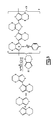
- FIG. 2 An example of the polymer, PEDOT, is provided in FIG. 2 .
- a particular object of the present invention is to provide an improved monomer solution wherein the degradation is mitigated thereby leading to an improved polymer upon treatment with an oxidizer.
- a special feature of the present invention is the ability to provide a capacitor with improved, lower, ESR and the capacitor can be provided at a lower cost, with increased manufacturing efficiency and with higher consistency in the measured ESR across large numbers of manufactured capacitors.
- the method includes forming anode of a valve metal.
- a dielectric is formed on the anode.
- An intrinsically conductive polymer is formed on the dielectric by coating the dielectric with a monomer solution comprising a monomer of an intrinsically conductive polymer and at least one alkaline material. The monomer is then polymerized.
- the method includes forming anodes of a valve metal or valve metal oxide; forming a dielectric on each anode of the anodes; forming a monomer solution comprising a monomer of an intrinsically conducting polymer; treating the monomer solution with at least one of an alkaline material and an ion exchange material to achieve a first pH of at least 4 to no more than 7; forming an intrinsically conductive polymer on each said dielectric by coating the dielectric with the monomer solution; and polymerizing the monomer.
- FIG. 1 illustrates the structure of a solid electrolytic capacitor having an intrinsically conductive polymer cathode.
- FIG. 2 illustrates the steps in the polymerization of 3,4-ethylenedioxythiophene in the presence of Fe (III) p-toluenensulfonate
- FIG. 3 illustrates the polymerization of 3,4-ethylenedioxythiophene in the presence of a protic (Br ⁇ nsted) acid.
- an improved capacitor and the method for making the improved capacitor utilizing improved monomer. More particularly, provided herein is a method that allows the production of such a capacitor with consistency.
- High polymer conductivity preferably up to about 1000 S/cm, is essential for low ESR applications of conductive polymer capacitors.
- Extensive efforts have been made to achieve further ESR reduction, including the application of various types of oxidants and dopants, the incorporation of various materials to “stabilize” the conductive polymer, and other ongoing process optimizations. It has been found that higher conductivity of the polymer can be achieved using monomer with pH above 4. Moreover, the consistency of the monomer solution and resulting conductive polymer film can be improved by maintaining a pH above 4.
- the presence of acid in the monomer tends to initiate “acid catalyzed” side reactions, which directly compete with the desired polymerization reaction.
- the suggested steps are illustrated in FIG. 3 .
- the acid catalyzed reactions yield non-conjugated dihydrothiophene molecules which lead to poor conductivity, while the oxidative polymerization as shown in FIG. 2 , produces highly conductive material with high degrees of conjugation.
- the ESR of conductive polymer capacitors are negatively affected by the presence of acid catalyzed reaction products due to the increased resistance of the conductive polymer matrix (lower degree of conjugation).
- the acid catalyzed reactions should be prevented from occurring, or at least be suppressed to minimize its negative impact. If not suppressed, the pH of the solution could continue to drop to pH 3 and below due to further acid accumulation. Efforts were made to remove the accumulated acid content from monomer solution. As stated, pH is an indicator of the acidity of the solution, and should be controlled in the pH range from about 4 to 7, more preferably from about 4 to 6, and most preferably from about 4.5 to 5.5.
- the preferred alkaline materials include metallic oxides, metal hydroxides, organic bases, and basic organic salts.
- the examples include, but are not limited to alkali metal oxides and hydroxides, alkaline earth metal oxides and hydroxides, ferric hydroxide, organic amines such as dimethyl amine and diethyl amine, alkanolamines such as diethanol amine, aminoalcohols such as 2-amino-2-methyl-1-propanol (trade name AMP-95 from Angus Chemicals, Buffalo Grove, Ill.).
- Monomer 3,4-ethylenedioxythipene is a liquid at room temperature and readily distilled under vacuum to produce a clean-cut fraction of very high purity. Impurities such as water, solvent and other contaminants have been found to distill off well below the boiling point of EDOT so that at the end of the distillation process a pure monomer is available. A fresh, regenerated solution of non-aqueous monomer may be reconstituted for the coating process.
- a continuous manufacturing process wherein the monomer solution is continuously, or periodically, passed from the dipping container, through a purification device, such as a basic anion exchange column and returned to the dipping container.
- a purification device such as a basic anion exchange column and returned to the dipping container.
- This continually removes acid built up during the polymerization process and eliminates the need for replacing the monomer solution.
- the pH of the purified monomer solution is determined and subsequently monitored. Once a predetermined decrease from the initial pH is reached, say a pH change of 0.5, the solution is circulated through a purification cycle. The frequency of the test and purification cycle is dependent on the number of capacitors being manufactured over a period of time.
- the primary culprits in the acidification of the monomer solution are believed to be acid accumulation from the oxidizer or from polymerization reaction by-products. Repetitive dipping steps into the monomer or monomer solution cause the increased acidity of the system. One way of removing these acidic species is through precipitation at reduced temperatures followed by filtration of the precipitates. Other methods of treating the monomer solution to remove the acidic material comprise at least one of distillation and recrystallization. Evidence of the buildup of both wanted and unwanted products from the “aging” of monomer can be found via gas chromatography measurements. Using 3,4-ethylenedioxythiophene as an example, the peaks for the monomer, non-conjugated dimer, and conjugated dimer are distinguishable.
- non-conjugated peak (dihydrothiophene) grows in intensity during usage. It has been found that the content of non-conjugated dihydrothiophene in the monomer solution should be controlled to under 10 wt %, more preferably under 5 wt % and most preferably under 2 wt %.
- aniline, polypyrrole and thiophene when used herein to refer to the monomer or a polymer thereof refers to unsubstituted or substituted compounds or derivatives equally unless a specific compound is being referred to specifically.
- a bar of 470 ⁇ F 4V rated tantalum anodes with a size of 4.90 mm ⁇ 3.25 mm ⁇ 1.70 mm was dipped into a solution of Fe (III) p-toluenesulfonate (oxidant), dried, and subsequently dipped into fresh 3,4-ethylenedioxythiophene (monomer).
- the anodes were washed to remove excess monomer and byproducts of the reactions after polymerization which formed a thin layer of conductive polymer (PEDOT) on the dielectric surface of the anodes.
- PEDOT conductive polymer
- the anodes were then reformed, i.e., subjected to a DC voltage in a diluted phosphoric acid solution to repair any damage to the dielectric and therefore, reducing the DC leakage. This dipping-reforming process cycle was repeated until a thick polymer layer was formed. Carbon and silver coatings were applied onto the anodes by conventional process and ESR of the capacitors was measured at 100 KHz. The test result is listed in Table 2.
- the anodes were washed to remove excess monomer and by-products of the reactions after the completion of polymerization which formed a thin layer of conductive polymer (PEDOT) on the dielectric of the anodes.
- PEDOT conductive polymer
- the anodes were then subjected to a DC voltage, or reformed, in a diluted phosphoric acid solution to reduce DC leakage. This dipping-reforming process cycle was repeated until a thick polymer layer was formed. Carbon and silver coatings were applied onto the anodes. ESR of the capacitors was measured in the same way as described in the comparative example. The test result is listed in Table 2.
- the anodes were washed to remove excess monomer and by-products of the reactions after the completion of polymerization, which formed a thin layer of conductive polymer (PEDOT) on the dielectric surface of the anodes.
- PEDOT conductive polymer
- the anodes were then subjected to a DC voltage, or reformed, in a diluted phosphoric acid solution to reduce DC leakage. This dipping-reforming process cycle was repeated until a thick polymer layer was formed. Carbon and silver coatings were applied onto the anodes. ESR of the capacitors was measured in the same way as described in the comparative example. The test result is listed in Table 2.
- the anodes were washed to remove excess monomer and byproducts of the reactions after the completion of polymerization, which formed a thin layer of conductive polymer (PEDOT) on the dielectric of the anodes.
- the anodes were then subjected to a DC voltage, or reformed, in a diluted phosphoric acid solution to reduce DC leakage. This dipping-reforming process cycle was repeated until a thick polymer layer was formed. Carbon and silver coatings were applied onto the anodes. ESR of the capacitors was measured in the same way as described in the comparative example. The test result is listed in Table 2.
- This invention is useful for improving the quality of capacitors which are used throughout the electronics industry.
Abstract
Description
| TABLE 1 |
| pH values obtained for comparative compositions |
| pH using H2O | |||
| Sample Description | extraction | ||
| Monomer as received | pH 4.71 | ||
| Monomer after use | pH 3.76-3.85 | ||
| Used monomer after distillation | pH 5.40 | ||
| Deionized Water as Control | pH 6.89 | ||
| TABLE 2 |
| Impact of monomer quality on ESR* |
| ESR, mΩ | ||
| Comparative Example | 15.7 | ||
| Example 1 | 45.3 | ||
| Example 2 | 15.8 | ||
| Example 3 | 16.3 | ||
| *ESR was measured at 100 KHz. | |||
Claims (42)
Priority Applications (3)
| Application Number | Priority Date | Filing Date | Title |
|---|---|---|---|
| US11/787,378 US7754276B2 (en) | 2007-04-16 | 2007-04-16 | Process for manufacturing low ESR conductive polymer based solid electrolytic capacitors |
| CN2008800120364A CN101663719B (en) | 2007-04-16 | 2008-04-16 | Process for manufacturing low ESR conductive polymer based solid electrolytic capacitors |
| PCT/US2008/060503 WO2008131018A2 (en) | 2007-04-16 | 2008-04-16 | Process for manufacturing low esr conductive polymer based solid electrolytic capacitors |
Applications Claiming Priority (1)
| Application Number | Priority Date | Filing Date | Title |
|---|---|---|---|
| US11/787,378 US7754276B2 (en) | 2007-04-16 | 2007-04-16 | Process for manufacturing low ESR conductive polymer based solid electrolytic capacitors |
Publications (2)
| Publication Number | Publication Date |
|---|---|
| US20080250620A1 US20080250620A1 (en) | 2008-10-16 |
| US7754276B2 true US7754276B2 (en) | 2010-07-13 |
Family
ID=39852405
Family Applications (1)
| Application Number | Title | Priority Date | Filing Date |
|---|---|---|---|
| US11/787,378 Active 2028-11-10 US7754276B2 (en) | 2007-04-16 | 2007-04-16 | Process for manufacturing low ESR conductive polymer based solid electrolytic capacitors |
Country Status (3)
| Country | Link |
|---|---|
| US (1) | US7754276B2 (en) |
| CN (1) | CN101663719B (en) |
| WO (1) | WO2008131018A2 (en) |
Cited By (7)
| Publication number | Priority date | Publication date | Assignee | Title |
|---|---|---|---|---|
| US20080222862A1 (en) * | 2007-03-15 | 2008-09-18 | Sanyo Electric Co., Ltd. | Method for manufacturing solid electrolytic capacitor and solid electrolytic capacitor |
| US9928964B1 (en) | 2013-08-28 | 2018-03-27 | Kemet Electronics Corporation | Preparation of conjugated dimer and products formed therefrom |
| US10340091B2 (en) | 2016-05-19 | 2019-07-02 | Kemet Electronics Corporation | Polyanion copolymers for use with conducting polymers in solid electrolytic capacitors |
| US10658121B2 (en) | 2017-10-18 | 2020-05-19 | Kemet Electronics Corporation | Process for forming a solid electrolytic capacitor |
| US10943742B2 (en) | 2017-10-18 | 2021-03-09 | Kemet Electronics Corporation | Conductive polymer dispersion for improved reliability |
| US11177076B2 (en) | 2017-10-18 | 2021-11-16 | Kemet Electronics Corporation | Conductive polymer capacitor for improved reliability |
| DE112021004836T5 (en) | 2020-09-17 | 2023-07-13 | Kemet Electronics Corporation | CONDUCTIVE POLYMER DISPERSION FOR IMPROVED RELIABILITY |
Families Citing this family (9)
| Publication number | Priority date | Publication date | Assignee | Title |
|---|---|---|---|---|
| US7852615B2 (en) * | 2008-01-22 | 2010-12-14 | Avx Corporation | Electrolytic capacitor anode treated with an organometallic compound |
| EP2619778B1 (en) * | 2010-09-21 | 2019-02-27 | Kemet Electronics Corporation | Solid electrolytic capacitor and method of manufacturing a solid electrolytic capacitor |
| US9583273B2 (en) | 2010-09-21 | 2017-02-28 | Kemet Electronics Corporation | Solid electrolytic capacitor and method of manufacturing a solid electrolytic capacitor |
| CN102820138B (en) * | 2012-09-03 | 2015-09-02 | 中国振华(集团)新云电子元器件有限责任公司 | A kind of in-situ oxidizing-polymerizing prepares intrinsic high connductivity polymer electrolytic capacitor method |
| CN105074854B (en) | 2013-02-19 | 2019-03-26 | 凯米特电子公司 | Low ESR capacitor |
| CN103489657A (en) * | 2013-10-17 | 2014-01-01 | 中国振华(集团)新云电子元器件有限责任公司 | Preparation method of high-conductivity polymer electrolytic capacitor |
| CN107112139B (en) * | 2014-12-25 | 2019-07-26 | 松下知识产权经营株式会社 | The manufacturing method of electrolytic capacitor |
| CN111093958B (en) * | 2017-09-08 | 2022-10-28 | 威里利生命科学有限责任公司 | Self-healing lead in a humid environment |
| CN109655521A (en) * | 2019-01-28 | 2019-04-19 | 中国地质科学院水文地质环境地质研究所 | Based on Accelerator mass spectrometry14The method for fast measuring of C |
Citations (5)
| Publication number | Priority date | Publication date | Assignee | Title |
|---|---|---|---|---|
| JPH11121279A (en) * | 1997-10-09 | 1999-04-30 | Sanyo Electric Co Ltd | Organic solid electrolytic capacitor and manufacturing method therefor |
| US6110379A (en) * | 1996-03-11 | 2000-08-29 | Overton; James Michael | Method for treating water containing sulfate |
| JP2001244151A (en) | 2000-02-28 | 2001-09-07 | Showa Denko Kk | Method for regenerating monomer-containing liquid for formation of polymer electrolyte |
| US6334966B1 (en) * | 2000-11-06 | 2002-01-01 | Kemet Electronics Corporation | Chemical oxidative preparation of conductive polymers |
| US7479166B2 (en) | 2006-10-12 | 2009-01-20 | Sanyo Electric Co., Ltd. | Method of manufacturing solid electrolytic capacitor |
Family Cites Families (6)
| Publication number | Priority date | Publication date | Assignee | Title |
|---|---|---|---|---|
| JP3251208B2 (en) * | 1997-07-24 | 2002-01-28 | 富山日本電気株式会社 | Method for manufacturing solid electrolytic capacitor |
| JP3478987B2 (en) * | 1999-02-10 | 2003-12-15 | 松下電器産業株式会社 | Method for manufacturing solid electrolytic capacitor |
| WO2003088287A1 (en) * | 2002-03-28 | 2003-10-23 | Nippon Chemi-Con Corporation | Solid electrolytic capacitor and process for producing the same |
| JP2004281607A (en) * | 2003-03-14 | 2004-10-07 | Nippon Chemicon Corp | Method for manufacturing solid electrolytic capacitor |
| US6798644B1 (en) * | 2003-07-10 | 2004-09-28 | Kemet Electronics Corporation | ESR of solid electrolytic capacitors using conductive polymer cathodes |
| JP2005101350A (en) * | 2003-09-25 | 2005-04-14 | Nippon Chemicon Corp | Method of manufacture solid electrolytic capacitor |
-
2007
- 2007-04-16 US US11/787,378 patent/US7754276B2/en active Active
-
2008
- 2008-04-16 CN CN2008800120364A patent/CN101663719B/en active Active
- 2008-04-16 WO PCT/US2008/060503 patent/WO2008131018A2/en active Application Filing
Patent Citations (5)
| Publication number | Priority date | Publication date | Assignee | Title |
|---|---|---|---|---|
| US6110379A (en) * | 1996-03-11 | 2000-08-29 | Overton; James Michael | Method for treating water containing sulfate |
| JPH11121279A (en) * | 1997-10-09 | 1999-04-30 | Sanyo Electric Co Ltd | Organic solid electrolytic capacitor and manufacturing method therefor |
| JP2001244151A (en) | 2000-02-28 | 2001-09-07 | Showa Denko Kk | Method for regenerating monomer-containing liquid for formation of polymer electrolyte |
| US6334966B1 (en) * | 2000-11-06 | 2002-01-01 | Kemet Electronics Corporation | Chemical oxidative preparation of conductive polymers |
| US7479166B2 (en) | 2006-10-12 | 2009-01-20 | Sanyo Electric Co., Ltd. | Method of manufacturing solid electrolytic capacitor |
Non-Patent Citations (3)
| Title |
|---|
| Machine translation of JP 11121279 to Takamatsu obtained Feb. 29, 2009 from . * |
| Machine translation of JP 11121279 to Takamatsu obtained Feb. 29, 2009 from <http://dossier1.ipdl.inpit.go.jp/AIPN/odse—top—dn.ipdl?N0000=7400>. * |
| Sotoh et al., Structure and properties of polypyrrole synthesis under air and oxygen-free conditions, Synthetic Materials 84 (1997) 167-168. * |
Cited By (8)
| Publication number | Priority date | Publication date | Assignee | Title |
|---|---|---|---|---|
| US20080222862A1 (en) * | 2007-03-15 | 2008-09-18 | Sanyo Electric Co., Ltd. | Method for manufacturing solid electrolytic capacitor and solid electrolytic capacitor |
| US8057553B2 (en) * | 2007-03-15 | 2011-11-15 | Sanyo Electric Co., Ltd. | Method for manufacturing solid electrolytic capacitor and solid electrolytic capacitor |
| US9928964B1 (en) | 2013-08-28 | 2018-03-27 | Kemet Electronics Corporation | Preparation of conjugated dimer and products formed therefrom |
| US10340091B2 (en) | 2016-05-19 | 2019-07-02 | Kemet Electronics Corporation | Polyanion copolymers for use with conducting polymers in solid electrolytic capacitors |
| US10658121B2 (en) | 2017-10-18 | 2020-05-19 | Kemet Electronics Corporation | Process for forming a solid electrolytic capacitor |
| US10943742B2 (en) | 2017-10-18 | 2021-03-09 | Kemet Electronics Corporation | Conductive polymer dispersion for improved reliability |
| US11177076B2 (en) | 2017-10-18 | 2021-11-16 | Kemet Electronics Corporation | Conductive polymer capacitor for improved reliability |
| DE112021004836T5 (en) | 2020-09-17 | 2023-07-13 | Kemet Electronics Corporation | CONDUCTIVE POLYMER DISPERSION FOR IMPROVED RELIABILITY |
Also Published As
| Publication number | Publication date |
|---|---|
| US20080250620A1 (en) | 2008-10-16 |
| CN101663719B (en) | 2011-11-09 |
| WO2008131018A2 (en) | 2008-10-30 |
| CN101663719A (en) | 2010-03-03 |
| WO2008131018A3 (en) | 2008-12-18 |
Similar Documents
| Publication | Publication Date | Title |
|---|---|---|
| US7754276B2 (en) | Process for manufacturing low ESR conductive polymer based solid electrolytic capacitors | |
| EP2622018B1 (en) | Layer compositions with improved electrical parameters comprising pedot/pss and a stabilizer | |
| KR101803997B1 (en) | A Method for improving electrical parameters in capacitors comprising PEDOT/PSS as a solid electrolyte through a polyalkylene glycol | |
| US8771381B2 (en) | Process for producing electrolytic capacitors and capacitors made thereby | |
| TWI450907B (en) | Method for the preparation of conductive polymer dispersion, conductive polymer material made therefrom and solid electrolytic capacitor using the material | |
| KR101638993B1 (en) | Method for the production of electrolyte capacitors with polymer intermediate layer | |
| US7990683B2 (en) | High voltage solid electrolytic capacitors using conductive polymer slurries | |
| US8273135B2 (en) | Method of manufacturing solid electrolytic capacitor | |
| US10570520B2 (en) | Preparation of conjugated dimer and products formed therefrom | |
| JP5388811B2 (en) | Solid electrolytic capacitor and manufacturing method thereof | |
| KR101516838B1 (en) | Stabilised thiophene derivatives | |
| US7760490B2 (en) | Solid electrolytic capacitor and method of manufacturing solid electrolytic capacitor | |
| JP6233952B2 (en) | Conductive polymer dispersion for production of solid electrolytic capacitor and solid electrolytic capacitor produced using the same | |
| JP4342607B2 (en) | Oxidizing agent and dopant for conductive polymer synthesis, alcohol solution thereof, conductive polymer and solid electrolytic capacitor | |
| CN108885942B (en) | Electrolytic capacitor | |
| US7842104B2 (en) | Method of manufacturing solid electrolytic capacitor | |
| TWI428943B (en) | Solid electrolyte capacitor and production method thereof | |
| EP1551043B1 (en) | Solid electrolytic capacitor | |
| US20080224090A1 (en) | Method of manufacturing solid electrolytic capacitor | |
| JP5557638B2 (en) | Oxidant solution for producing conductive polymer and method for producing solid electrolytic capacitor using the same | |
| CN115702467A (en) | Solid electrolytic capacitor containing moisture-proof layer | |
| JP2006104314A (en) | METHOD FOR PURIFYING pi-CONJUGATED CONDUCTIVE POLYMER AND ELECTRICAL ENERGY STORAGE DEVICE AND SEMICONDUCTOR DEVICE | |
| JP2023502945A (en) | Compositions, polymers for capacitors and capacitors | |
| EP2305685B1 (en) | Stabilised thiophene derivatives | |
| JP2004128033A (en) | Method of manufacturing solid state electrolytic capacitor |
Legal Events
| Date | Code | Title | Description |
|---|---|---|---|
| AS | Assignment |
Owner name: KEMET ELECTRONICS CORPORATION, SOUTH CAROLINA Free format text: ASSIGNMENT OF ASSIGNORS INTEREST;ASSIGNORS:QIU, YONGJIAN;CHEN, QINGPING;LESSNER, PHILIP M.;AND OTHERS;REEL/FRAME:019268/0637 Effective date: 20070411 |
|
| AS | Assignment |
Owner name: K FINANCING, LLC, CALIFORNIA Free format text: SECURITY AGREEMENT;ASSIGNOR:KEMET CORPORATION;REEL/FRAME:022892/0795 Effective date: 20090630 Owner name: K FINANCING, LLC,CALIFORNIA Free format text: SECURITY AGREEMENT;ASSIGNOR:KEMET CORPORATION;REEL/FRAME:022892/0795 Effective date: 20090630 |
|
| AS | Assignment |
Owner name: KEMET CORPORATION,SOUTH CAROLINA Free format text: RELEASE OF SECURITY INTEREST RECORDED AT REEL/FRAME 022892/0795;ASSIGNOR:K FINANCING, LLC;REEL/FRAME:024397/0774 Effective date: 20100505 Owner name: KEMET CORPORATION, SOUTH CAROLINA Free format text: RELEASE OF SECURITY INTEREST RECORDED AT REEL/FRAME 022892/0795;ASSIGNOR:K FINANCING, LLC;REEL/FRAME:024397/0774 Effective date: 20100505 |
|
| STCF | Information on status: patent grant |
Free format text: PATENTED CASE |
|
| AS | Assignment |
Owner name: BANK OF AMERICA, N.A. AS AGENT, NEW YORK Free format text: SECURITY INTEREST;ASSIGNOR:KEMET ELECTRONICS CORPORATION;REEL/FRAME:025150/0023 Effective date: 20100930 |
|
| FPAY | Fee payment |
Year of fee payment: 4 |
|
| AS | Assignment |
Owner name: BANK OF AMERICA, N.A., AS COLLATERAL AGENT, NORTH Free format text: SECURITY AGREEMENT;ASSIGNORS:KEMET CORPORATION;KEMET ELECTRONICS CORPORATION;KEMET BLUE POWDER CORPORATION;REEL/FRAME:042523/0639 Effective date: 20170505 Owner name: BANK OF AMERICA, N.A., AS COLLATERAL AGENT, NORTH CAROLINA Free format text: SECURITY AGREEMENT;ASSIGNORS:KEMET CORPORATION;KEMET ELECTRONICS CORPORATION;KEMET BLUE POWDER CORPORATION;REEL/FRAME:042523/0639 Effective date: 20170505 |
|
| MAFP | Maintenance fee payment |
Free format text: PAYMENT OF MAINTENANCE FEE, 8TH YEAR, LARGE ENTITY (ORIGINAL EVENT CODE: M1552) Year of fee payment: 8 |
|
| AS | Assignment |
Owner name: KEMET BLUE POWDER CORPORATION, NEVADA Free format text: RELEASE BY SECURED PARTY;ASSIGNOR:BANK OF AMERICA, N.A.;REEL/FRAME:047450/0926 Effective date: 20181107 Owner name: KEMET ELECTRONICS CORPORATION, FLORIDA Free format text: RELEASE BY SECURED PARTY;ASSIGNOR:BANK OF AMERICA, N.A.;REEL/FRAME:047450/0926 Effective date: 20181107 Owner name: KEMET CORPORATION,, FLORIDA Free format text: RELEASE BY SECURED PARTY;ASSIGNOR:BANK OF AMERICA, N.A.;REEL/FRAME:047450/0926 Effective date: 20181107 |
|
| MAFP | Maintenance fee payment |
Free format text: PAYMENT OF MAINTENANCE FEE, 12TH YEAR, LARGE ENTITY (ORIGINAL EVENT CODE: M1553); ENTITY STATUS OF PATENT OWNER: LARGE ENTITY Year of fee payment: 12 |