US7753749B2 - Swim fin - Google Patents
Swim fin Download PDFInfo
- Publication number
- US7753749B2 US7753749B2 US12/164,211 US16421108A US7753749B2 US 7753749 B2 US7753749 B2 US 7753749B2 US 16421108 A US16421108 A US 16421108A US 7753749 B2 US7753749 B2 US 7753749B2
- Authority
- US
- United States
- Prior art keywords
- bevel
- swim fin
- fin
- blade portion
- trailing
- Prior art date
- Legal status (The legal status is an assumption and is not a legal conclusion. Google has not performed a legal analysis and makes no representation as to the accuracy of the status listed.)
- Expired - Fee Related, expires
Links
Images


Classifications
-
- A—HUMAN NECESSITIES
- A63—SPORTS; GAMES; AMUSEMENTS
- A63B—APPARATUS FOR PHYSICAL TRAINING, GYMNASTICS, SWIMMING, CLIMBING, OR FENCING; BALL GAMES; TRAINING EQUIPMENT
- A63B31/00—Swimming aids
- A63B31/08—Swim fins, flippers or other swimming aids held by, or attachable to, the hands, arms, feet or legs
- A63B31/10—Swim fins, flippers or other swimming aids held by, or attachable to, the hands, arms, feet or legs held by, or attachable to, the hands or feet
- A63B31/11—Swim fins, flippers or other swimming aids held by, or attachable to, the hands, arms, feet or legs held by, or attachable to, the hands or feet attachable only to the feet
Definitions
- the present invention relates to one or a pair of fins used in water related activities, especially, but not exclusively, in training by race swimmers.
- Swim fins also called flippers or swimming fins, are used in water related activities to increase the surface area of the user's foot. With the larger surface area, the user is able to displace more water and propel themselves much faster relative to the water medium than with a bare foot.
- fins are constructed with a substantial increase in surface area.
- the increase is made primarily in the blade portion, e.g., roughly the area forward of the user's toes and to a lesser extent the sides of the user's foot to gain maximum advantage from the portion of the leg muscles that are strongest during the propulsion component of a swim kick, the up beat.
- a large blade provides distinct disadvantages for other users, especially users who want or need a fast cycle of kicking since on the non-propulsion component of a swim kick, e.g., the down beat, the enlarged blade portion creates drag that must be overcome.
- a dive fin has relatively large surface area in comparison to other fin types to overcome the additional weight that scuba divers carry. Accordingly, divers typically swim at languid pace. The same fin is unsuitable for race swimmers, who swim at a fast rate. The drag induced by the large blade portion would hinder the swimmer on the down beat.
- race swimmers condition their arms and shoulders in addition to their legs.
- swimmers seek to achieve a high cycle rate of shoulder and arm movement alongside a leg movement.
- the legs often tire before the arms and shoulders, because the legs unlike the arms are constantly in water and must fight against water resistance.
- race swimmers turn to swim fins to maintain a training pace.
- a short-swim fin provides an opportunity for a race swimmer to condition their arms and shoulders while permitting the legs to kick at a sustained rate.
- Another solution is to maintain the enlarged blade portion and make the fin more flexible.
- this leads to a fin having a large size that is difficult to maneuver on land and difficult to use in race swimming circumstances including turns made against a wall in a pool.
- a swim fin in accordance with one or more embodiments of the present invention, includes a foot pocket and a blade portion.
- the blade portion includes a top surface and a bottom surface.
- An opening is disposed through the blade portion to permit an enhanced directional fluid flow between the top and the bottom surface.
- a top bevel is disposed in the top surface and surrounds the opening.
- the top bevel includes a trailing and a leading top bevel area to compress the fluid flow.
- the swim fin includes a trailing or a leading top bevel area, which is larger than the other of the trailing and the leading top bevel area, and a trailing and a leading bottom bevel areas are substantially equal in size to retard fluid flow through the opening.
- a swim fin in accordance with one or more embodiments of the present invention, includes a foot bed and a cover having a substantially convex shape.
- the cover encloses a portion of the foot bed to form a foot pocket for a user's foot.
- the cover includes a blade portion having a plurality of openings, where at least one opening is associated with a bevel for providing an enhanced directional fluid flow.
- FIGS. 1 a - 1 d are top, left, right, and bottom views, respectively, of a swim fin in accordance with one or more embodiments of the present invention.
- FIG. 2 is a bottom view of the fin of FIG. 1 and illustrating the blade portion.
- FIGS. 3 a and 3 b are detailed views of a portion of FIG. 1 and illustrating the openings and bevel.
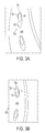
- FIGS. 4 a - 4 f are top views of swim fins in accordance with one or more embodiment of the present invention.
- FIGS. 5 a - 5 f are top views of swim fins in accordance with one or more embodiment of the present invention.
- FIGS. 1 a - 1 d are top, left, right, and bottom views, respectively, of a swim fin in accordance with one or more embodiments of the present invention.
- FIG. 2 is a bottom view of the fin of FIG. 1 and illustrating the blade portion.
- FIGS. 3 a and 3 b are detailed views of a portion of FIG. 1 and illustrating the openings and bevel.
- the swim fin of the present invention is illustrated as a right-foot swim fin.
- a left-foot fin is a mirror image of a right-foot fin.
- the present invention is intended to encompass a right-foot fin, a left-foot fin, as well as a pair of fins.
- a swim fin 10 preferably comprises a short blade design suitable and is intended for use in fluid medium in a lake, sea, and/or pool, and may be used not only for swim training, but also for diving and/or other activities.
- Fin 10 includes a foot pocket 12 that is defined in a longitudinal direction by a heel end 14 and a toe end 16 and in the lateral direction and height by a foot bed 18 and a cover 20 .
- the foot pocket suitably receives the user's foot; and, thus, to accommodate different user's feet, fin 10 may be available in different sizes.
- Fin 10 may be made of any suitable material, but for optimum performance is made of a material comprising a rubber and/or rubber-plastic material that provides suitable flexibility, yet maintains its shape.
- fin 10 comprises a structure that is substantially semi-rigid, as discussed further below.
- the heel end comprises a strap 14 a and is configured as an open heel end. However, heel end 14 may also be enclosed as is generally known in the art. Similarly, toe end 16 comprises a reinforced edge structure 16 a defining an opening 16 b . However, toe end 16 may also be closed as is generally known in the art.
- Foot bed 18 may be substantially U-shaped in cross-section to cradle the user's foot.
- the U-shape of the foot bed preferably comprises a flat surface such that a user is comfortable walking on the foot bed and side portions that may be rounded upward to meet a cover.
- the intersection of the foot bed and cover define an inside, e.g., left, edge 18 a and an outside, e.g., right, edge 18 b , with respect to the user's foot.
- the foot bed further comprises a heel edge 18 c and toe edge 18 d.
- Each edge of the foot bed may have any suitable shape, but, preferably, each edge in is ergonomic to the user's foot while providing a structurally durable and stable fin.
- heel edge 18 c may be curved and toe edge 18 d may be U-shaped.
- Cover 20 encloses at least a portion of the foot pocket between the inside and outside edges 18 a , 18 b .
- the top portion further includes an inside edge 20 a , an outside edge 20 b , a front edge 20 c , and a rear edge 20 d , which together define the limits of a top surface 20 e .
- Rear edge 20 d and/or strap 14 a preferably comprise a soft rubber beads for a comfort fitting.
- the top portion also includes a blade portion 24 used for propulsion.
- the blade portion comprises a top surface 24 a and a bottom surface 24 b .
- the blade portion is defined as the region of the cover between foot bed inside edge 18 a and top portion inside edge 20 a , foot bed outside edge 18 b and top portion outside edge 20 b , and front edge 20 c and which boundary is marked by broken lines in FIG. 2 .
- front edge 20 c is also the front edge of the blade portion and edges 20 and 2 b are edges of the blade portion.
- Cover 20 includes one or more channelization edges 22 in top surface 20 e , e.g., top surface 24 a .
- edges 22 comprise a pair of edges 22 a , 22 b that approximately follow edges 18 a , 18 b and a generally U-shaped edge 22 c proximate to an upper portion of a user's foot.
- Edges 22 a and 22 b define a fluid flow channel therebetween, which aids in reducing drag around the user's foot.
- edges 22 a , 22 b may define fluid flow lines around the user's foot.
- U-shaped edge 22 c preferably includes a shelf 22 d that also aids in directing fluid flow and reduces drag.
- cover 20 preferably comprises a generally convex shape (relative to the foot bed) in cross-section at the blade portion such that blade portion 24 is configured as a scoop for scooping water on the up beat of the swimmer's kick.
- the top surface may vary in shape throughout the fin and may have a more pronounced convex shape toward rear edge 20 d and less at front edge 20 c.
- edges 20 a and 20 b are preferably elongated to enlarge the effective volume of the scoop and increase the effectiveness of the blade portion.
- the convex shape of the cover provides a semi-rigid shape that helps the fin, e.g., the blade portion, maintain a semi-rigid shape.
- Front edge 20 c preferably comprises a compound curve that includes a radially inward curve proximate interior edge 20 a and a radially exterior curve proximate to outside edge 20 b . These curves align anatomically with the foot of a user, wherein the front edge is more distal from the rear of the fin at the big toe, e.g., hallux, than at the little toe. In this manner, the blade portion is provided with an anatomically advantageous size.
- Openings 30 are disposed in the blade portion and aid the user in his or her activities by permitting a fluid flow through the opening in general and reducing drag, e.g., fluid resistance, on a portion of the swim kick, preferably the non-propulsion portion of the swim kick. Openings 30 may be arranged in a grouping 40 as discussed below.
- Openings 30 preferably are associated with one or more bevels that permit a greater fluid flow from one side of the blade portion to the other side than vice versa, i.e., an enhanced directional fluid flow.
- a top surface bevel 32 a may be disposed in top surface 24 a and a bottom surface bevel 32 b may be disposed in bottom surface 24 b .
- Each bevel is defined by a rim, which surrounds the opening, and, thus, the bevel provides a transition from the respective top or bottom surface to the opening.
- Bevel 32 a is defined by a rim 32 c at the level of the surrounding top surface
- bevel 32 b is defined by a respective rim 32 d at the level of the surrounding bottom surface.
- top bevel 32 a comprises a trailing bevel area 32 e more distal from front edge 20 c than a leading bevel area 32 f and which is larger than the trailing bevel area.
- each opening is configured as an oval shape and is disposed in top surface 24 a off-center in the respective bevel 32 a such that leading bevel area 32 f is larger than trailing bevel area 32 e.
- bottom bevel 32 b comprises a trailing bevel area 32 g more distal from front edge 20 c than a leading bevel area 32 h .
- Leading bevel area 32 h and trailing bevel area 32 g may have an equal size.
- top surface bevel 32 a is larger than bottom surface bevel 32 b and, thus, top surface bevel 24 a reduces water resistance more than bottom surface bevel 32 b resulting in compressed water flow through respective opening 30 .
- the larger top surface bevel 32 b promotes a faster down beat and results in faster as well as higher beats per cycle, while the smaller bottom surface bevel 32 b retard fluid flow through the opening and promote greater propulsion on the propulsion portion of the swim kick, e.g., the up beat.
- fin 10 comprises one or more groupings 40 of at least one opening 30 disposed along a fluid flow line.
- fin 10 may comprise a grouping 40 a and 40 b of openings that are serially placed respectively between edges 22 a , 22 b , and edges 20 a , 20 b along a fluid flow line.
- One or more openings 30 may comprise a grouping 40 c proximal to front edge 20 c.
- fin 10 comprises a length of 14.00 inches from a rear portion of strap 14 a to a front-most portion of front edge 20 c , a width of 7.00 inches from edge 20 a to edge 20 b at a widest most part, and a distance between the end portions of strap 14 a of 3.25 inches.
- the ratio of the surface area of the blade portion to the surface area of the foot bed preferably comprises 1.1 or greater.
- the ratio of the length to width of the fin preferably is 2.0 or less.
- FIGS. 4 a - 4 f are top views of fins in accordance with one or more embodiments of the present invention.
- fins 50 a - 50 f are substantially constructed as taught with respect to fin 10 .
- each fin comprises a particular grouping of fins that are suitable for specific types of activities and for differing swimming abilities. Thus, a swimmer who is adept and who wishes to swim at a great speed may wish to train with a greater number of openings.
- Fin 50 a comprises a grouping 40 d of openings 30 that are located proximal to edges 20 a and 20 b .
- the openings are preferably arranged in a staggered pattern. While fin 50 a omits an opening in the central forward area, fin 50 b includes such an opening and has similar groupings of openings 30 as fin 10 . However, openings 30 in fin 50 b are less oval.
- Fins 50 c - 50 f concentrate the openings in an area proximal to front edge 20 c . Therein, the size and the number of openings are varied. Moreover, fins 50 a and 50 d - 50 f comprise a bevel 32 a configured to have trailing bevel area 32 e that is larger than the leading bevel area 32 f.
- FIGS. 5 a - 5 f are top views of fins in accordance with one or more embodiments of the present invention.
- fins 60 a - 60 f are substantially constructed as taught with respect with fin 10 .
- fins 60 a , 60 c , 60 e , and 60 f comprise one or more additional fluid flow edges 22 e - 22 f that help direct the fluid flow on the top surface.
- Fins 60 b - 60 f may also include one or more shaped edges 23 that help in directing fluid flow.
Landscapes
- Health & Medical Sciences (AREA)
- General Health & Medical Sciences (AREA)
- Physical Education & Sports Medicine (AREA)
- Devices For Medical Bathing And Washing (AREA)
Abstract
Description
Claims (18)
Priority Applications (1)
| Application Number | Priority Date | Filing Date | Title |
|---|---|---|---|
| US12/164,211 US7753749B2 (en) | 2008-06-30 | 2008-06-30 | Swim fin |
Applications Claiming Priority (1)
| Application Number | Priority Date | Filing Date | Title |
|---|---|---|---|
| US12/164,211 US7753749B2 (en) | 2008-06-30 | 2008-06-30 | Swim fin |
Publications (2)
| Publication Number | Publication Date |
|---|---|
| US20090325434A1 US20090325434A1 (en) | 2009-12-31 |
| US7753749B2 true US7753749B2 (en) | 2010-07-13 |
Family
ID=41447999
Family Applications (1)
| Application Number | Title | Priority Date | Filing Date |
|---|---|---|---|
| US12/164,211 Expired - Fee Related US7753749B2 (en) | 2008-06-30 | 2008-06-30 | Swim fin |
Country Status (1)
| Country | Link |
|---|---|
| US (1) | US7753749B2 (en) |
Cited By (4)
| Publication number | Priority date | Publication date | Assignee | Title |
|---|---|---|---|---|
| US20150164177A1 (en) * | 2013-12-15 | 2015-06-18 | Paul E. Hohmann | Nozzle shoe |
| US20160051005A1 (en) * | 2013-12-15 | 2016-02-25 | Paul E. Hohmann | Nozzle shoe |
| US9364717B2 (en) | 2014-01-16 | 2016-06-14 | Kathleen Davis | Swimming fin |
| US10981036B2 (en) * | 2019-05-23 | 2021-04-20 | Harrison Marsland | Variable aquatic training aid |
Families Citing this family (2)
| Publication number | Priority date | Publication date | Assignee | Title |
|---|---|---|---|---|
| US9186554B2 (en) | 2013-09-13 | 2015-11-17 | Randall Wade Lord | Swim fin for leg amputees |
| CN115089942B (en) * | 2022-06-28 | 2023-08-22 | 东莞市仁通泳潜装备科技有限公司 | Frog shoe capable of increasing web waterpower |
Citations (60)
| Publication number | Priority date | Publication date | Assignee | Title |
|---|---|---|---|---|
| US915457A (en) | 1908-07-01 | 1909-03-16 | Louis Marrotte | Swimming-shoe. |
| US1786451A (en) | 1927-06-10 | 1930-12-30 | Ribard Jean Louis | Oar blade or the like |
| US1841904A (en) | 1928-04-17 | 1932-01-19 | Mcgowan Harold Arthur | Device to aid persons in swimming |
| US2099973A (en) | 1933-04-06 | 1937-11-23 | Corlieu Louis Marie De | Lifesaving and swimming propelling device |
| US2588363A (en) | 1945-06-19 | 1952-03-11 | Corlieu Louis Marie De | Crawl-fins |
| US2672629A (en) | 1949-04-14 | 1954-03-23 | Trell Jack K La | Swimmer's propulsion aid |
| GB746764A (en) | 1953-03-23 | 1956-03-21 | E T Skinner & Company Ltd | Improvements in or relating to swim-fins |
| US2889563A (en) | 1956-02-27 | 1959-06-09 | Edward W Lamb | Swim flipper |
| US3055025A (en) | 1959-04-20 | 1962-09-25 | Ferraro Luigi | Swimming fins or flippers |
| US3183529A (en) | 1964-03-16 | 1965-05-18 | Beuchat Georges | Swimmer's foot-fin with thrust-accelerating device |
| US3422470A (en) | 1966-09-13 | 1969-01-21 | Lodovico Mares | Swimming fin |
| GB1223664A (en) | 1969-04-29 | 1971-03-03 | Paul Beuchat | Improvements in or relating to swim-fins |
| US3649979A (en) | 1970-06-15 | 1972-03-21 | U S Divers Co | Swim fin |
| US3913158A (en) | 1970-04-08 | 1975-10-21 | Nemrod Metzeler Sa | Swimming fins |
| US4083071A (en) | 1976-01-20 | 1978-04-11 | Roland Forjot | Swim flippers |
| US4627820A (en) | 1985-06-18 | 1986-12-09 | Penebre Larry M | Swim fin |
| US4775343A (en) | 1985-11-12 | 1988-10-04 | Undersea Industries, Inc. | Hydrodynamic swim fin |
| US4913418A (en) * | 1988-11-25 | 1990-04-03 | Speedshop, Inc. | Swim and exercise paddle improvement |
| US4923419A (en) | 1986-09-30 | 1990-05-08 | Mccarthy Kevin I | Positive drive swim fin |
| US4948385A (en) | 1988-12-30 | 1990-08-14 | Hall Martin P | Training fin device for swimming |
| US5100328A (en) | 1990-01-23 | 1992-03-31 | Badgley Laurence E | Memory scanning device |
| US5292272A (en) | 1993-06-28 | 1994-03-08 | Grim Roger W | Dual mode swim fin |
| USD349552S (en) | 1993-01-27 | 1994-08-09 | Manta Surfing Products | Swim fin |
| US5387145A (en) | 1993-07-07 | 1995-02-07 | Wagner; John L. | Swim fins |
| US5417599A (en) | 1994-02-25 | 1995-05-23 | Evans; Robert B. | Swim fin having multiple interchangeable components |
| US5588890A (en) | 1994-05-20 | 1996-12-31 | Htm Sport S.P.A. | Swimming fin |
| USD379398S (en) | 1995-09-27 | 1997-05-20 | Dean Garraffa | Swim fin |
| US5702277A (en) | 1993-07-07 | 1997-12-30 | Wagner; John Lee | High performance swim fin |
| US5709575A (en) | 1997-02-25 | 1998-01-20 | Betrock; Irving | Practice swim fin with perforations |
| US5746631A (en) | 1996-01-11 | 1998-05-05 | Mccarthy; Peter T. | High efficiency hydrofoil and swim fin designs |
| US5975973A (en) | 1997-06-06 | 1999-11-02 | Sontaria Holdings Pty Ltd. | Swim fin |
| US6053788A (en) * | 1997-09-12 | 2000-04-25 | Htm Sport S.P.A. | Swimming flipper |
| US6152794A (en) | 1999-05-14 | 2000-11-28 | Liu; Yen-Wei | Swim fin |
| US6179675B1 (en) | 1998-09-10 | 2001-01-30 | Cressi-Sub S.P.A. | Swimming fin and manufacture process thereof |
| US6224443B1 (en) | 2000-03-10 | 2001-05-01 | Earth & Ocean Sports, Inc. | Multilayer swim fin and method |
| US6290560B1 (en) | 2000-05-29 | 2001-09-18 | Guy Robert Kidd | Fin and fin system |
| USD450365S1 (en) | 2001-01-22 | 2001-11-13 | Robert B. Evans | Swim fin having downturned tips |
| US6371821B1 (en) | 1996-01-11 | 2002-04-16 | Nature's Wing Fin Designs, Llc | High efficiency hydrofoil and swim fin designs |
| US6379203B1 (en) | 2000-12-07 | 2002-04-30 | Tzong-Fuh Kuo | Swimming fins |
| US6394863B1 (en) | 2000-10-11 | 2002-05-28 | Chien-Rung Chen | Fin with movable flap |
| US6435926B1 (en) | 2000-04-04 | 2002-08-20 | Taong In Yeh | Adjusting strap structure for swim fins |
| USD463840S1 (en) | 2001-11-09 | 2002-10-01 | Zura Sports, Inc. | Swim fin |
| US6482059B2 (en) | 1997-05-09 | 2002-11-19 | Mccarthy Peter T. | High efficiency hydrofoil and swim fin designs |
| US6568974B2 (en) | 2000-09-29 | 2003-05-27 | Scubapro Europe S.R.L. | Swim and scuba fin |
| US6568973B2 (en) | 2000-02-25 | 2003-05-27 | Salvas Sub S.P.A. | Swim or dive fin |
| US6620009B1 (en) | 2002-04-22 | 2003-09-16 | The United States Of America As Represented By The Secretary Of The Navy | Method of making selective multiple contour high efficiency swim fins |
| US6663452B1 (en) | 2002-10-22 | 2003-12-16 | Robert J. Myers | Aquatic fins |
| US20040053547A1 (en) | 2002-09-13 | 2004-03-18 | Cressi-Sub S.P.A | Differentiated rigidity swimming fin with hydrodynamically designed rearward shoe strap connection |
| US6712656B2 (en) | 1998-05-14 | 2004-03-30 | Mccarthy Peter T. | Methods for creating consistent large scale blade deflections |
| US20050003719A1 (en) | 1998-05-14 | 2005-01-06 | Mccarthy Peter T. | Methods for creating large scale focused blade deflections |
| US6884134B2 (en) | 2002-07-19 | 2005-04-26 | Mccarthy Peter T. | High deflection hydrofoils and swim fins |
| US20050186866A1 (en) | 2004-01-20 | 2005-08-25 | Mccarthy Peter T. | Dual adjustable strap designs for swim fins |
| US7077715B2 (en) | 2002-09-12 | 2006-07-18 | Pod Ware Pty Ltd. | Swim fins and method of manufacture thereof |
| US7115011B2 (en) | 2004-07-30 | 2006-10-03 | Chien-Kuan Chen | Swim fin |
| US20060249630A1 (en) | 2002-06-26 | 2006-11-09 | Mccarthy Peter T | High efficiency tip vortex reversal and induced drag reduction |
| US20060264499A1 (en) | 2003-06-23 | 2006-11-23 | Wright Amy E | Novel biologically active lasonolide compounds |
| USD534983S1 (en) | 2004-07-26 | 2007-01-09 | Salvas Sub S.P.A. | Fin |
| US7172480B2 (en) | 2004-09-30 | 2007-02-06 | Aqua Lung America, Inc. | Bungee flipper |
| US20070077831A1 (en) | 2005-09-30 | 2007-04-05 | Yu-I Kuo | Fins |
| USD553218S1 (en) | 2005-03-15 | 2007-10-16 | Warnaco Swimwear Incorporated | Swim exercise fin |
-
2008
- 2008-06-30 US US12/164,211 patent/US7753749B2/en not_active Expired - Fee Related
Patent Citations (73)
| Publication number | Priority date | Publication date | Assignee | Title |
|---|---|---|---|---|
| US915457A (en) | 1908-07-01 | 1909-03-16 | Louis Marrotte | Swimming-shoe. |
| US1786451A (en) | 1927-06-10 | 1930-12-30 | Ribard Jean Louis | Oar blade or the like |
| US1841904A (en) | 1928-04-17 | 1932-01-19 | Mcgowan Harold Arthur | Device to aid persons in swimming |
| US2099973A (en) | 1933-04-06 | 1937-11-23 | Corlieu Louis Marie De | Lifesaving and swimming propelling device |
| US2588363A (en) | 1945-06-19 | 1952-03-11 | Corlieu Louis Marie De | Crawl-fins |
| US2672629A (en) | 1949-04-14 | 1954-03-23 | Trell Jack K La | Swimmer's propulsion aid |
| GB746764A (en) | 1953-03-23 | 1956-03-21 | E T Skinner & Company Ltd | Improvements in or relating to swim-fins |
| US2889563A (en) | 1956-02-27 | 1959-06-09 | Edward W Lamb | Swim flipper |
| US3055025A (en) | 1959-04-20 | 1962-09-25 | Ferraro Luigi | Swimming fins or flippers |
| US3183529A (en) | 1964-03-16 | 1965-05-18 | Beuchat Georges | Swimmer's foot-fin with thrust-accelerating device |
| US3422470A (en) | 1966-09-13 | 1969-01-21 | Lodovico Mares | Swimming fin |
| GB1223664A (en) | 1969-04-29 | 1971-03-03 | Paul Beuchat | Improvements in or relating to swim-fins |
| US3913158A (en) | 1970-04-08 | 1975-10-21 | Nemrod Metzeler Sa | Swimming fins |
| US3649979A (en) | 1970-06-15 | 1972-03-21 | U S Divers Co | Swim fin |
| US4083071A (en) | 1976-01-20 | 1978-04-11 | Roland Forjot | Swim flippers |
| US4627820A (en) | 1985-06-18 | 1986-12-09 | Penebre Larry M | Swim fin |
| US4775343A (en) | 1985-11-12 | 1988-10-04 | Undersea Industries, Inc. | Hydrodynamic swim fin |
| US4923419A (en) | 1986-09-30 | 1990-05-08 | Mccarthy Kevin I | Positive drive swim fin |
| US4913418A (en) * | 1988-11-25 | 1990-04-03 | Speedshop, Inc. | Swim and exercise paddle improvement |
| US4948385A (en) | 1988-12-30 | 1990-08-14 | Hall Martin P | Training fin device for swimming |
| US5100328A (en) | 1990-01-23 | 1992-03-31 | Badgley Laurence E | Memory scanning device |
| USD349552S (en) | 1993-01-27 | 1994-08-09 | Manta Surfing Products | Swim fin |
| US5292272A (en) | 1993-06-28 | 1994-03-08 | Grim Roger W | Dual mode swim fin |
| US5387145A (en) | 1993-07-07 | 1995-02-07 | Wagner; John L. | Swim fins |
| US5702277A (en) | 1993-07-07 | 1997-12-30 | Wagner; John Lee | High performance swim fin |
| US5417599A (en) | 1994-02-25 | 1995-05-23 | Evans; Robert B. | Swim fin having multiple interchangeable components |
| US5588890A (en) | 1994-05-20 | 1996-12-31 | Htm Sport S.P.A. | Swimming fin |
| USD379398S (en) | 1995-09-27 | 1997-05-20 | Dean Garraffa | Swim fin |
| US5746631A (en) | 1996-01-11 | 1998-05-05 | Mccarthy; Peter T. | High efficiency hydrofoil and swim fin designs |
| US6146224A (en) | 1996-01-11 | 2000-11-14 | Mccarthy; Peter T. | High efficiency hydrofoil and swim fin designs |
| US7101240B2 (en) | 1996-01-11 | 2006-09-05 | Mccarthy Peter T | High efficiency hydrofoil and swim fin designs |
| US6719599B2 (en) | 1996-01-11 | 2004-04-13 | Mccarthy Peter T. | High efficiency hydrofoil and swim fin designs |
| US6607411B1 (en) | 1996-01-11 | 2003-08-19 | Mccarthy Peter T. | High efficiency hydrofoil and swim fin designs |
| US6585548B2 (en) | 1996-01-11 | 2003-07-01 | Mccarthy Peter T. | High efficiency hydrofoil and swim fin designs |
| US6371821B1 (en) | 1996-01-11 | 2002-04-16 | Nature's Wing Fin Designs, Llc | High efficiency hydrofoil and swim fin designs |
| US6497597B2 (en) | 1996-01-11 | 2002-12-24 | Mccarthy Peter T. | High efficiency hydrofoil and swim fin designs |
| US5709575A (en) | 1997-02-25 | 1998-01-20 | Betrock; Irving | Practice swim fin with perforations |
| US6482059B2 (en) | 1997-05-09 | 2002-11-19 | Mccarthy Peter T. | High efficiency hydrofoil and swim fin designs |
| US5975973A (en) | 1997-06-06 | 1999-11-02 | Sontaria Holdings Pty Ltd. | Swim fin |
| US6053788A (en) * | 1997-09-12 | 2000-04-25 | Htm Sport S.P.A. | Swimming flipper |
| US20050003719A1 (en) | 1998-05-14 | 2005-01-06 | Mccarthy Peter T. | Methods for creating large scale focused blade deflections |
| US6918805B2 (en) | 1998-05-14 | 2005-07-19 | Mccarthy Peter T. | Methods for creating consistent large scale blade deflections |
| US7018256B2 (en) | 1998-05-14 | 2006-03-28 | Mccarthy Peter T | Methods for creating large scale focused blade deflections |
| US6843693B2 (en) | 1998-05-14 | 2005-01-18 | Mccarthy Peter T. | Methods for creating large scale focused blade deflections |
| US6712656B2 (en) | 1998-05-14 | 2004-03-30 | Mccarthy Peter T. | Methods for creating consistent large scale blade deflections |
| US20050181689A1 (en) | 1998-05-14 | 2005-08-18 | Mccarthy Peter T. | Methods for creating consistent large scale blade deflections |
| US20070032147A1 (en) | 1998-05-14 | 2007-02-08 | Mccarthy Peter T | Methods for creating large scale focused blade deflections |
| US6179675B1 (en) | 1998-09-10 | 2001-01-30 | Cressi-Sub S.P.A. | Swimming fin and manufacture process thereof |
| US6152794A (en) | 1999-05-14 | 2000-11-28 | Liu; Yen-Wei | Swim fin |
| US6568973B2 (en) | 2000-02-25 | 2003-05-27 | Salvas Sub S.P.A. | Swim or dive fin |
| US6224443B1 (en) | 2000-03-10 | 2001-05-01 | Earth & Ocean Sports, Inc. | Multilayer swim fin and method |
| US6435926B1 (en) | 2000-04-04 | 2002-08-20 | Taong In Yeh | Adjusting strap structure for swim fins |
| US6290560B1 (en) | 2000-05-29 | 2001-09-18 | Guy Robert Kidd | Fin and fin system |
| US6568974B2 (en) | 2000-09-29 | 2003-05-27 | Scubapro Europe S.R.L. | Swim and scuba fin |
| US6394863B1 (en) | 2000-10-11 | 2002-05-28 | Chien-Rung Chen | Fin with movable flap |
| US6379203B1 (en) | 2000-12-07 | 2002-04-30 | Tzong-Fuh Kuo | Swimming fins |
| USD450365S1 (en) | 2001-01-22 | 2001-11-13 | Robert B. Evans | Swim fin having downturned tips |
| USD463840S1 (en) | 2001-11-09 | 2002-10-01 | Zura Sports, Inc. | Swim fin |
| US6620009B1 (en) | 2002-04-22 | 2003-09-16 | The United States Of America As Represented By The Secretary Of The Navy | Method of making selective multiple contour high efficiency swim fins |
| US20060249630A1 (en) | 2002-06-26 | 2006-11-09 | Mccarthy Peter T | High efficiency tip vortex reversal and induced drag reduction |
| US20070037459A1 (en) | 2002-07-19 | 2007-02-15 | Mccarthy Peter T | High deflection hydrofoils and swim fins |
| US6884134B2 (en) | 2002-07-19 | 2005-04-26 | Mccarthy Peter T. | High deflection hydrofoils and swim fins |
| US20050176318A1 (en) | 2002-07-19 | 2005-08-11 | Mccarthy Peter T. | High deflection hydrofoils and swim fins |
| US7077715B2 (en) | 2002-09-12 | 2006-07-18 | Pod Ware Pty Ltd. | Swim fins and method of manufacture thereof |
| US20040053547A1 (en) | 2002-09-13 | 2004-03-18 | Cressi-Sub S.P.A | Differentiated rigidity swimming fin with hydrodynamically designed rearward shoe strap connection |
| US6663452B1 (en) | 2002-10-22 | 2003-12-16 | Robert J. Myers | Aquatic fins |
| US20060264499A1 (en) | 2003-06-23 | 2006-11-23 | Wright Amy E | Novel biologically active lasonolide compounds |
| US20050186866A1 (en) | 2004-01-20 | 2005-08-25 | Mccarthy Peter T. | Dual adjustable strap designs for swim fins |
| USD534983S1 (en) | 2004-07-26 | 2007-01-09 | Salvas Sub S.P.A. | Fin |
| US7115011B2 (en) | 2004-07-30 | 2006-10-03 | Chien-Kuan Chen | Swim fin |
| US7172480B2 (en) | 2004-09-30 | 2007-02-06 | Aqua Lung America, Inc. | Bungee flipper |
| USD553218S1 (en) | 2005-03-15 | 2007-10-16 | Warnaco Swimwear Incorporated | Swim exercise fin |
| US20070077831A1 (en) | 2005-09-30 | 2007-04-05 | Yu-I Kuo | Fins |
Non-Patent Citations (3)
| Title |
|---|
| Speedo Glide Fin, Downloaded Jun. 6, 2008. |
| Torpedo Swim Fin, Downloaded May 16, 2007. |
| Vapor Swim Fin, Image taken Jun. 7, 2007. |
Cited By (6)
| Publication number | Priority date | Publication date | Assignee | Title |
|---|---|---|---|---|
| US20150164177A1 (en) * | 2013-12-15 | 2015-06-18 | Paul E. Hohmann | Nozzle shoe |
| US9204684B2 (en) * | 2013-12-15 | 2015-12-08 | Paul E. Hohmann | Nozzle shoe |
| US20160051005A1 (en) * | 2013-12-15 | 2016-02-25 | Paul E. Hohmann | Nozzle shoe |
| US9661895B2 (en) * | 2013-12-15 | 2017-05-30 | Paul E. Hohmann | Nozzle shoe |
| US9364717B2 (en) | 2014-01-16 | 2016-06-14 | Kathleen Davis | Swimming fin |
| US10981036B2 (en) * | 2019-05-23 | 2021-04-20 | Harrison Marsland | Variable aquatic training aid |
Also Published As
| Publication number | Publication date |
|---|---|
| US20090325434A1 (en) | 2009-12-31 |
Similar Documents
| Publication | Publication Date | Title |
|---|---|---|
| US20220241651A1 (en) | Swimming assistance appratus | |
| US7753749B2 (en) | Swim fin | |
| US6764362B1 (en) | Monofin swimming apparatus | |
| TWI874643B (en) | A fin and fin blade | |
| JP4072106B2 (en) | Improved swimming training fins | |
| JPH0211177A (en) | Foot fin for swimming | |
| US5259798A (en) | Swim fin | |
| JP2852815B2 (en) | Swimming fins with different stiffness characteristics | |
| USRE23006E (en) | Swim fin | |
| US20090270001A1 (en) | Paddle to Pop-up Device | |
| AU2000246509B2 (en) | Spear blade swim fin | |
| US9750981B2 (en) | Apparatus and method for an improved hand fin | |
| US20060068659A1 (en) | Bungee flipper | |
| US5188552A (en) | Swimming aid | |
| AU2000246509A1 (en) | Spear blade swim fin | |
| WO2021064665A1 (en) | Swim fin with a longitudinally moulded blade | |
| WO2007000394A1 (en) | Swim fin | |
| US10478672B1 (en) | Walkable water shoe with incorporated swim fin appendage | |
| US11325006B2 (en) | Surfing glove | |
| KR102064093B1 (en) | Swimming assistance apparatus | |
| KR102658781B1 (en) | Swimming assistance apparatus | |
| KR102171415B1 (en) | Swimming assistance apparatus | |
| KR102116642B1 (en) | Swimming assistance apparatus | |
| RU13873U1 (en) | SWIMMING DEVICE (OPTIONS) | |
| GB2409415A (en) | Swimming aid |
Legal Events
| Date | Code | Title | Description |
|---|---|---|---|
| AS | Assignment |
Owner name: WARNACO SWIMWEAR, INC., CALIFORNIA Free format text: ASSIGNMENT OF ASSIGNORS INTEREST;ASSIGNORS:MUN, JOHN;STIFF, CRAIG;REEL/FRAME:021275/0904 Effective date: 20080711 |
|
| AS | Assignment |
Owner name: BANK OF AMERICA, N.A., NEW YORK Free format text: PATENT SECURITY AGREEMENT;ASSIGNORS:WARNACO INC.;WARNACO U.S., INC.;WARNACO SWIMWEAR INC.;AND OTHERS;REEL/FRAME:021450/0111 Effective date: 20080826 |
|
| STCF | Information on status: patent grant |
Free format text: PATENTED CASE |
|
| AS | Assignment |
Owner name: JPMORGAN CHASE BANK, NA, AS COLLATERAL AGENT, TEXA Free format text: SECURITY AGREEMENT;ASSIGNORS:WARNACO INC.;WARNACO SWIMWEAR INC.;WARNACO SWIMWEAR PRODUCTS INC.;AND OTHERS;REEL/FRAME:026465/0503 Effective date: 20110617 |
|
| AS | Assignment |
Owner name: WARNACO SWIMWEAR PRODUCTS INC., CALIFORNIA Free format text: RELEASE;ASSIGNOR:JPMORGAN CHASE BANK, N.A.;REEL/FRAME:029900/0357 Effective date: 20130213 Owner name: WARNACO SWIMWEAR INC., CALIFORNIA Free format text: RELEASE;ASSIGNOR:JPMORGAN CHASE BANK, N.A.;REEL/FRAME:029900/0357 Effective date: 20130213 Owner name: WARNACO INC., NEW YORK Free format text: RELEASE;ASSIGNOR:JPMORGAN CHASE BANK, N.A.;REEL/FRAME:029900/0357 Effective date: 20130213 Owner name: CCC ACQUISITION CORP., NEW YORK Free format text: RELEASE;ASSIGNOR:JPMORGAN CHASE BANK, N.A.;REEL/FRAME:029900/0357 Effective date: 20130213 |
|
| AS | Assignment |
Owner name: BARCLAYS BANK PLC, AS COLLATERAL AGENT, NEW YORK Free format text: PATENT SECURITY AGREEMENT;ASSIGNOR:WARNACO SWIMWEAR INC.;REEL/FRAME:030111/0672 Effective date: 20130213 |
|
| AS | Assignment |
Owner name: WARNACO U.S., INC., NEW YORK Free format text: TERMINATION OF SECURITY INTEREST;ASSIGNOR:BANK OF AMERICA, N.A.;REEL/FRAME:030583/0365 Effective date: 20130213 Owner name: WARNACO SWIMWEAR PRODUCTS INC., NEW YORK Free format text: TERMINATION OF SECURITY INTEREST;ASSIGNOR:BANK OF AMERICA, N.A.;REEL/FRAME:030583/0365 Effective date: 20130213 Owner name: WARNACO SWIMWEAR INC., NEW YORK Free format text: TERMINATION OF SECURITY INTEREST;ASSIGNOR:BANK OF AMERICA, N.A.;REEL/FRAME:030583/0365 Effective date: 20130213 Owner name: CCC ACQUISITION CORP., NEW YORK Free format text: TERMINATION OF SECURITY INTEREST;ASSIGNOR:BANK OF AMERICA, N.A.;REEL/FRAME:030583/0365 Effective date: 20130213 Owner name: WARNACO INC., NEW YORK Free format text: TERMINATION OF SECURITY INTEREST;ASSIGNOR:BANK OF AMERICA, N.A.;REEL/FRAME:030583/0365 Effective date: 20130213 |
|
| FPAY | Fee payment |
Year of fee payment: 4 |
|
| MAFP | Maintenance fee payment |
Free format text: PAYMENT OF MAINTENANCE FEE, 8TH YEAR, LARGE ENTITY (ORIGINAL EVENT CODE: M1552) Year of fee payment: 8 |
|
| AS | Assignment |
Owner name: WARNACO U.S., INC., NEW YORK Free format text: RELEASE BY SECURED PARTY;ASSIGNOR:BARCLAYS BANK PLC, AS COLLATERAL AGENT;REEL/FRAME:049049/0124 Effective date: 20190429 Owner name: WARNACO SWIMWEAR PRODUCTS INC., CALIFORNIA Free format text: RELEASE BY SECURED PARTY;ASSIGNOR:BARCLAYS BANK PLC, AS COLLATERAL AGENT;REEL/FRAME:049049/0124 Effective date: 20190429 Owner name: WARNACO SWIMWEAR INC., CALIFORNIA Free format text: RELEASE BY SECURED PARTY;ASSIGNOR:BARCLAYS BANK PLC, AS COLLATERAL AGENT;REEL/FRAME:049049/0124 Effective date: 20190429 Owner name: PVH CORP., NEW YORK Free format text: RELEASE BY SECURED PARTY;ASSIGNOR:BARCLAYS BANK PLC, AS COLLATERAL AGENT;REEL/FRAME:049049/0124 Effective date: 20190429 |
|
| FEPP | Fee payment procedure |
Free format text: MAINTENANCE FEE REMINDER MAILED (ORIGINAL EVENT CODE: REM.); ENTITY STATUS OF PATENT OWNER: LARGE ENTITY |
|
| LAPS | Lapse for failure to pay maintenance fees |
Free format text: PATENT EXPIRED FOR FAILURE TO PAY MAINTENANCE FEES (ORIGINAL EVENT CODE: EXP.); ENTITY STATUS OF PATENT OWNER: LARGE ENTITY |
|
| STCH | Information on status: patent discontinuation |
Free format text: PATENT EXPIRED DUE TO NONPAYMENT OF MAINTENANCE FEES UNDER 37 CFR 1.362 |
|
| FP | Lapsed due to failure to pay maintenance fee |
Effective date: 20220713 |