US7739938B2 - Gas generator launcher for small unmanned aerial vehicles (UAVs) - Google Patents
Gas generator launcher for small unmanned aerial vehicles (UAVs) Download PDFInfo
- Publication number
- US7739938B2 US7739938B2 US11/856,037 US85603707A US7739938B2 US 7739938 B2 US7739938 B2 US 7739938B2 US 85603707 A US85603707 A US 85603707A US 7739938 B2 US7739938 B2 US 7739938B2
- Authority
- US
- United States
- Prior art keywords
- barrel
- gas generator
- projectile
- gas
- body portion
- Prior art date
- Legal status (The legal status is an assumption and is not a legal conclusion. Google has not performed a legal analysis and makes no representation as to the accuracy of the status listed.)
- Expired - Fee Related, expires
Links
Images


Classifications
-
- B—PERFORMING OPERATIONS; TRANSPORTING
- B64—AIRCRAFT; AVIATION; COSMONAUTICS
- B64F—GROUND OR AIRCRAFT-CARRIER-DECK INSTALLATIONS SPECIALLY ADAPTED FOR USE IN CONNECTION WITH AIRCRAFT; DESIGNING, MANUFACTURING, ASSEMBLING, CLEANING, MAINTAINING OR REPAIRING AIRCRAFT, NOT OTHERWISE PROVIDED FOR; HANDLING, TRANSPORTING, TESTING OR INSPECTING AIRCRAFT COMPONENTS, NOT OTHERWISE PROVIDED FOR
- B64F1/00—Ground or aircraft-carrier-deck installations
- B64F1/04—Launching or towing gear
-
- F—MECHANICAL ENGINEERING; LIGHTING; HEATING; WEAPONS; BLASTING
- F41—WEAPONS
- F41A—FUNCTIONAL FEATURES OR DETAILS COMMON TO BOTH SMALLARMS AND ORDNANCE, e.g. CANNONS; MOUNTINGS FOR SMALLARMS OR ORDNANCE
- F41A21/00—Barrels; Gun tubes; Muzzle attachments; Barrel mounting means
- F41A21/16—Barrels or gun tubes characterised by the shape of the bore
- F41A21/18—Grooves-Rifling
-
- F—MECHANICAL ENGINEERING; LIGHTING; HEATING; WEAPONS; BLASTING
- F41—WEAPONS
- F41B—WEAPONS FOR PROJECTING MISSILES WITHOUT USE OF EXPLOSIVE OR COMBUSTIBLE PROPELLANT CHARGE; WEAPONS NOT OTHERWISE PROVIDED FOR
- F41B11/00—Compressed-gas guns, e.g. air guns; Steam guns
- F41B11/60—Compressed-gas guns, e.g. air guns; Steam guns characterised by the supply of compressed gas
- F41B11/62—Compressed-gas guns, e.g. air guns; Steam guns characterised by the supply of compressed gas with pressure supplied by a gas cartridge
-
- F—MECHANICAL ENGINEERING; LIGHTING; HEATING; WEAPONS; BLASTING
- F41—WEAPONS
- F41F—APPARATUS FOR LAUNCHING PROJECTILES OR MISSILES FROM BARRELS, e.g. CANNONS; LAUNCHERS FOR ROCKETS OR TORPEDOES; HARPOON GUNS
- F41F1/00—Launching apparatus for projecting projectiles or missiles from barrels, e.g. cannons; Harpoon guns
-
- B—PERFORMING OPERATIONS; TRANSPORTING
- B64—AIRCRAFT; AVIATION; COSMONAUTICS
- B64U—UNMANNED AERIAL VEHICLES [UAV]; EQUIPMENT THEREFOR
- B64U70/00—Launching, take-off or landing arrangements
- B64U70/70—Launching or landing using catapults, tracks or rails
Definitions
- the embodiments herein generally relate to weapon deployment systems, and, more particularly, to weapon deployment systems used for small unmanned aerial vehicles (UAVs).
- UAVs small unmanned aerial vehicles
- UAVs are typically used in military operations such as for surveillance.
- Typical launchers used for UAVs are generally large, cumbersome, or costly to use, and sometimes require multiple people to operate, require special handling for proper deployment, and often require hand assembly of the UAV.
- Conventional launchers for launching small “fixed-wing” UAVs in the military include hydraulic/electric rail guns, elastic band type launchers, pneumatic launchers, and hand launchers.
- a novel weapons launcher for small UAVs capable of being used by one person in a rapid, simple, and cost effective manner.
- an embodiment herein provides a system for launching an unmanned projectile, wherein the system comprises a barrel comprising the projectile, a pusher cup positioned behind the projectile, guide rails adapted to prevent the projectile from rotating in the barrel, and a gas generator adapted to generate gas to propel the projectile out of the barrel.
- the system further comprises a pressure chamber operatively connected to the barrel, wherein the barrel extends out of a first end of the pressure chamber, wherein the pressure chamber is adapted to increase a pressure of the gas in the barrel, and wherein the pressure chamber comprises a front body portion operatively connected to the barrel; an aft body portion operatively connected to the front body portion and the gas generator; and a vent sleeve positioned around the front body portion and adapted to provide an aperture through which the gas exits the barrel in order to control a level of gas pressure in the barrel.
- the system further comprises a stand operatively connected to the aft body portion, wherein the stand is rotatable with respect to the barrel, wherein a triggering of the gas generator causes the pusher cup to push the projectile out of the barrel at a predetermined launch velocity in order to attain a predetermined self-propelled flight trajectory, and wherein the triggering causes the pusher cup to exit the barrel.
- the gas generator utilizes approximately 24Vdc of external electrical power to initiate functioning of the gas generator.
- the pressure chamber may comprise a plurality of interconnected sections adapted to vent propulsion gases created by the gas generator upon launch of the projectile.
- the barrel, the projectile, the gas generator, and the pusher cup are preferably expendable after each launch of the projectile.
- the vent sleeve may comprise a gas deflector adapted to redirect the vented propulsion gases forward and away from a user standing behind the barrel.
- the pusher cup preferably has a higher aerodynamic drag and lower inertia than the projectile, wherein as the projectile and the pusher cup exit the barrel, the higher aerodynamic drag and lower inertia of the pusher cup causes a rapid deceleration and separation of the pusher cup from the projectile, thereby allowing the projectile to continue a ballistic flight path prior to transition to a self-propelled flight.
- Another embodiment provides a method of launching unmanned projectiles, wherein the method comprises inserting a projectile into a barrel comprising a pusher cup positioned behind the projectile; attaching a gas generator to the barrel; connecting the gas generator and the barrel to a pressure chamber; initiating the gas generator to generate gas; pressurizing the gas; introducing the pressurized gas into the barrel; selectively venting the pressurized gas out of the barrel to control a level of gas pressure in the barrel; and the pressurized gas exerting force on the pusher cup causing the pusher cup to push the projectile out of the barrel at a predetermined launch velocity in order to attain a predetermined self-propelled flight trajectory, wherein the force causes the pusher cup to exit the barrel.
- the increase in the pressure creates a dynamic force applied to an upstream side of the pusher cup causing acceleration of the pusher cup and the projectile.
- the pusher cup preferably has a higher aerodynamic drag and lower inertia than the projectile, wherein as the projectile and the pusher cup exit the barrel, the higher aerodynamic drag and lower inertia of the pusher cup causes a rapid deceleration and separation of the pusher cup from the projectile, thereby allowing the projectile to continue a ballistic flight path prior to transition to a self-propelled flight.
- the method may further comprise redirecting the vented gas forward and away from a user standing behind the barrel.
- the inserting and attaching processes may occur in a pre-packaging of the barrel to include the projectile, the pusher cup, and the gas generator. Additionally, prior to the initiating process, the method may further comprise attaching the pressure chamber to a launcher mount assembly, wherein the pressure chamber is adapted to pressurize the gas, wherein the connecting process creates sufficient electrical and mechanical connections to allow the projectile to be prepared for launch.
- the pre-packaging of the barrel to include the projectile, the pusher cup, and the gas generator allows for a repeatable launch operation comprising launching the projectile; and replacing of a spent barrel with a new pre-packaged barrel comprising a new projectile, a new pusher cup, and a new gas generator.
- the gas generator utilizes approximately 24Vdc of external electrical power to initiate functioning of the gas generator.
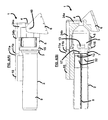
- FIG. 1 is a schematic diagram illustrating a perspective view of a gas generator launcher according to an embodiment herein;
- FIG. 2 is a schematic diagram illustrating a front view of the gas generator launcher of FIG. 1 according to an embodiment herein;
- FIG. 3 is a schematic diagram illustrating a top view of the gas generator launcher of FIG. 1 according to an embodiment herein;
- FIG. 4(A) is a schematic diagram illustrating a side view of the gas generator launcher of FIG. 1 according to an embodiment herein;
- FIG. 4(B) is a schematic diagram illustrating a cross-sectional view of the gas generator launcher of FIG. 4(A) according to an embodiment herein;
- FIG. 5 is a schematic diagram illustrating a perspective view of the pusher cup of the gas generator launcher of FIG. 4(B) according to an embodiment herein;
- FIG. 6 is a schematic diagram illustrating a perspective view of the launcher mount of the gas generator launcher of FIG. 1 according to an embodiment herein;
- FIG. 7 is a schematic diagram illustrating a perspective view of the barrel of the gas generator launcher of FIG. 1 according to an embodiment herein;
- FIG. 8 is a schematic diagram illustrating a perspective view of the pressure chamber of the gas generator launcher of FIG. 1 according to an embodiment herein;
- FIG. 9(A) is a schematic diagram illustrating a perspective view of the front body of the pressure chamber of FIG. 8 according to an embodiment herein;
- FIG. 9(B) is a schematic diagram illustrating a side view of the front body of FIG. 9(A) according to an embodiment herein;
- FIG. 10(A) is a schematic diagram illustrating a perspective view of the vent sleeve of the pressure chamber of FIG. 8 according to an embodiment herein;
- FIG. 10(B) is a schematic diagram illustrating a top view of the vent sleeve of FIG. 10(A) according to an embodiment herein;
- FIG. 10(C) is a schematic diagram illustrating a side view of the vent sleeve of FIG. 10(A) according to an embodiment herein;
- FIG. 10(D) is a schematic diagram illustrating a cross-sectional side view of the vent sleeve of FIG. 10(A) according to an embodiment herein;
- FIG. 11(A) is a schematic diagram illustrating a perspective view of the aft body of the pressure chamber of FIG. 8 according to an embodiment herein;
- FIGS. 11 (B) and 11 (C) are schematic diagrams illustrating side views of the aft body of FIG. 11(A) according to an embodiment herein;
- FIG. 11(D) is a schematic diagram illustrating a top view of the aft body of FIG. 11(A) according to an embodiment herein;
- FIGS. 12 and 14 are graphical representations illustrating the velocity of the UAV as a function of time according to the embodiments herein;
- FIGS. 13 and 15 are graphical representations illustrating the position of the UAV as a function of time according to the embodiments herein;
- FIG. 16 is a flow diagram illustrating a preferred method of launching an unmanned projectile according to an embodiment herein.
- FIGS. 1 through 16 where similar reference characters denote corresponding features consistently throughout the figures, there are shown preferred embodiments.
- FIGS. 1 through 4(B) illustrate a gas generator launcher 1 according to an embodiment herein.
- the launcher 1 comprises a barrel 2 , a launcher mount 6 , and a pressure chamber 16 .
- the barrel 2 comprises a single-section, lightweight, high-strength composite or plastic material and may further include a plurality of interconnected sections to accommodate a higher launch velocity.
- the barrel 2 is affixed to the pressure chamber 16 , which comprises a front body portion 3 , an aft body portion 4 , a vent sleeve 5 , and a first and second portion of a pressure conduit 24 a , 24 b .
- the total length of these three parts is approximately nine inches with a maximum diameter of approximately six inches.
- a gas generator 10 is operatively connected to the barrel 2 , wherein the gas generator 10 is connected to the pressure chamber 16 via the first portion of the pressure conduit 24 a and the second portion of the pressure conduit 24 b to allow for the unimpeded flow of gas in the gas generator 10 .
- the barrel 2 is affixed to the front body portion 3 of the pressure chamber 16 , which may be made of aluminum, via a locking mechanism 7 (best shown in FIG. 4(B) ) that allows for easy connection and removal of the barrel 2 .
- Any suitable locking mechanism 7 may be used that facilitates a proper securing of the barrel 2 to the front body portion 3 , and likewise, which can allow for easy removal of the barrel 2 from the front body portion 3 .
- a plurality of barrel rails 8 for example, two barrel rails 8 ) that guide a UAV or other type of projectile 32 (shown, for example, as a cylindrical projectile 32 in FIG.
- the gas generator 10 is mounted on the grooved base 36 in such a position so that when the barrel 2 is attached to the front body portion 3 via the locking mechanism 7 , the gas generator 10 also becomes properly connected to the launcher 1 .
- An example of a gas generator 10 that may be used is the S-100 multipurpose inflator available from Talley Defense Systems, Arizona, USA. In one embodiment, the gas generator 10 is approximately eight inches long and has a one-inch diameter. Moreover, in one embodiment, the gas generator 10 may be powered by TAL-1309 propellant also available from Talley Defense Systems, which, upon ignition, produces no toxic or flammable products.
- the gas generator 10 also incorporates an electrical interface 11 a , which is adjacent to electrical interface 11 b of the second portion of the pressure conduit 24 b , which allows for the connection of electrical leads (not shown) as the barrel 2 is attached to the pressure chamber 16 .
- the barrel 2 is expendable after use and thus contains its own gas generator 10 as well as a pre-loaded UAV 32 and pusher cup 12 allowing for easy shipping and transportation.
- the pusher cup 12 is used.
- the pusher cup 12 which is further illustrated in FIG. 5 , may be embodied as a lightweight piston that has an outer diameter slightly smaller than the inner diameter of the barrel 2 providing a low friction, pressure seal feature. As best shown in FIG.
- the pusher cup 12 is placed behind the UAV 32 in the barrel 2 providing a uniform surface that the pressurized gases are acting upon ensuring a consistent and repeatable launch velocity.
- the barrel rails 8 guide the pusher cup 12 as the pusher cup 12 travels down the barrel 2 .
- the pusher cup 12 comprises rail slides 33 configured on opposite sides of the outer wall 34 of the pusher cup 12 , which mate with the barrel rails 8 of the barrel 2 to allow the pusher cup 12 to slide in the barrel 2 without rotating.
- the launcher 1 is operatively connected to the launcher mount 6 , which allows for positioning of the launcher 1 at various angles.
- the launcher mount 6 is generally composed of three pieces: a rectangular base 25 with multiple tapped holes 26 for connection to two triangular sides 27 a , 27 b .
- each of the sides 27 a , 27 b comprise a hole 28 .
- FIG. 7 illustrates the barrel 2 in more detail.
- the barrel rails 8 are located on diametrically opposite sides of the inside of the barrel 2 .
- the grooved base 36 is shown extending outward from the exterior barrel wall 9 such that the shape of the grooved base 36 is configured to allow for proper seating of the gas generator 10 thereon.
- the pressure chamber 16 comprises a front body portion 3 , an aft body portion 4 , and a vent sleeve 5 .
- FIG. 8 illustrates a fully assembled pressure chamber 16 including the first portion of the pressure conduit 24 a and second portion of the pressure conduit 24 b .
- the front body portion 3 as depicted in FIGS. 9(A) and 9(B) , is generally cylindrically shaped and has a plurality of large vent holes 13 , which are cut into the middle wall 14 of the front body portion 3 , and which are covered by the vent sleeve 5 (best shown in FIG. 4(B) ).
- the front body portion 3 has a locking mechanism 7 configured in the lip 37 of the front body portion 3 to secure the barrel 2 to front body portion 3 .
- An angled neck portion 38 connects the lip 37 to the middle wall 14 of the front body portion 3 , which terminates with a generally cylindrical trunk 39 .
- the vent sleeve 5 is generally cylindrically shaped and is hollow to fit over the front body portion 3 .
- the vent sleeve 5 comprises a curved wall 18 with a gas deflector 15 attached so that when the vent holes 13 are opened, the vent sleeve 5 will direct the escaping gases towards the front body portion 3 of the launcher 1 rather than the aft body portion 4 so as to prevent any injuries to personnel located behind or to the side of the launcher 1 .
- the vent sleeve 5 which may be composed of aluminum, and the front body portion 3 are both rotatable so that the position of the vent sleeve 5 with respect to the front body portion 3 can be varied to either open or close the vent holes 13 to allow different quantities of the generated gas to be released into the atmosphere.
- the vent holes 13 can be opened or closed by turning the handles 19 of the vent sleeve 5 . When the vent holes 13 are sealed, the launcher 1 is in the maximum muzzle velocity condition. By increasing the amount of venting, the exit velocity of the UAV 32 can be reduced.
- FIGS. 11(A) through 11(D) illustrate the aft body portion 4 of the pressure chamber 16 (of FIG. 8 ).
- the aft body portion 4 is also generally cylindrically shaped with an attached first portion of the pressure conduit 24 a and second portion of the pressure conduit 24 b .
- the aft body portion 4 comprises an enlarged first portion 22 comprising flat surfaces 20 a , 20 b each comprising a hole 21 to align with hole 28 of the launcher mount 6 (of FIG. 6 ) for attachment thereto via attachment means 40 (shown in FIG. 4 (A)), which may comprise screws, bolts, rivets, pins, etc.
- the holes 21 , 28 with the attachment means 40 allow for the pressure chamber 16 to be rotatable with respect to the launcher mount 6 .
- the aft body portion 4 comprises an open end 30 that terminates to a base 31 that connects to the hole 29 .
- the aft body portion 4 further includes a smaller second portion 23 that provides for the attachment of the first portion of the pressure conduit 24 a to the open end 30 via hole 29 .
- the barrel 2 is attached (i.e., screwed, etc.) to the front body portion 3 .
- the barrel 2 is pre-packaged with a UAV 32 , pusher cup 12 , and gas generator 10 attached.
- the gas generator 10 is aligned with the second portion of the pressure conduit 24 b of the pressure chamber 16 .
- the gas generator 10 comprises electrical interface 11 a and the second portion of the pressure conduit 24 b comprises electrical interface 11 b such that when the gas generator 10 and second portion of the pressure conduit 24 b are aligned with one another, the electrical interfaces 11 a , 11 b also become aligned with respect to one another.
- the vent sleeve 5 is attached (i.e., screwed, etc.) onto the front body portion 3 from the rear.
- the aft body portion 4 is then attached (i.e., screwed, etc.) onto the front body portion 3 .
- the two mount sides 27 a , 27 b are attached (i.e., screwed, etc.) to the base 25 .
- the aft body portion 4 is attached (i.e., screwed, etc.) to the mount sides 27 a , 27 b and then the barrel 2 is positioned at the desired angle.
- the electrical interface 11 a is included with the gas generator 10 and terminates with wire leads (not shown).
- the launcher 1 is ready to be fired.
- an external electrical signal is sent to the gas generator 10 via electrical interface 11 a , 11 b beginning the pyrotechnic event and causing an almost instantaneous increase in pressure in the front body portion 3 of the pressure (expansion) chamber 16 .
- a dynamic force is applied to the upstream side 17 of the pusher cup 12 and both the pusher cup 12 and UAV 32 begin accelerating down the barrel 2 .
- the higher aerodynamic drag of the pusher cup 12 causes its rapid deceleration and separation from the UAV 32 allowing the UAV 32 to continue its ballistic flight path prior to its transition to self-propelled flight.
- the launcher 1 After launching the UAV 32 , the launcher 1 is ready to fire another UAV 32 simply by replacing the barrel 2 (with the preloaded UAV 32 and pusher cup 12 contained therein and the gas generator 10 affixed to the exterior of the barrel 2 ).
- the barrel 2 is preferably disposable and, depending on the situation, can either be discarded or used again by preparing the used barrel 2 with a new gas generator 10 , pusher cup 12 , and UAV 32 .
- the amount of volume available in the pressure chamber 16 when the UAV 32 and pusher cup 12 are in their starting position is approximately 0.004 m 3 and the area of the pusher cup 12 upon which the pressure is applied is 7.85 ⁇ 10 ⁇ 3 m 2 .
- Equation (2) represents the pressure curve given a 1-ft 3 volume (0.0283 m 3 ).
- V 1 V 2 must be applied to Equation (2) to represent the pressure in the pressure chamber 16 .
- v at (4) in which v is velocity and a is a constant acceleration
- the exit velocity of the UAV 32 can be correlated to the gas pressure by the following relations:
- Equation (6) By the derivative relationship between acceleration and velocity, Equation (6) can be rewritten as:
- Equation (9) indicates that the exit velocity of the UAV 32 will depend entirely upon the time that it is in the barrel 2 .
- the relationship between velocity and position can be used to determine the position of the UAV 32 at t final .
- s ⁇ vdt (10) in which s is the position.
- FIGS. 12 and 13 show the velocity and position of the UAV 32 as a function of time, respectively using the above equations.
- the time it takes for the UAV 32 to exit the launcher 1 is approximately 0.008 seconds.
- the velocity of the UAV 32 is approximately 115 m/s, which is significantly higher than the required velocity for flight of the UAV 32 .
- the required launch velocity can be achieved if the vent sleeve 5 is opened to reduce the pressure applied to the pusher cup 12 if the pressure is assumed to be constant as the UAV 32 travels down the barrel 2 .
- the pressure, P 2 is 954.9 kPa.
- the control volume is 0.0016 m 3 plus the volume of the barrel 2 , 0.0025 m 3 .
- the pressure in the barrel 2 , P 3 is 363.8 kPa. If it is assumed that the increase in volume is linear, the average value of the pressure is equal to:
- Equation (4) shows that the average pressure can be related to the average force, and the average force is calculated to be 5,175.9 N.
- the equation for position can be written in the standard linear form as:
- Equation (4) The exit velocity can be calculated with Equation (4) and is found to be 75.89 m/s. This analysis is similarly straightforward, but based on the calculations, the launch velocity is again significantly higher than that required by the UAV 32 for flight.
- both analyses indicate that the gas generator 10 is capable of providing the needed pressure for achieving launch velocity. However, if it is determined that the gas generator 10 is not producing the required pressure, the length of the barrel 2 can be altered by the addition of another 15.5-inch section to the barrel 2 . This would increase the launch velocity by increasing the time that the pressure is applied to the pusher cup 12 .
- the first analysis can be recalculated with a sixth order polynomial for the pressure curve approximation.
- the velocity can be calculated by the substitution of Equation (15) into Equation (8).
- the position s can be calculated by the integration of the obtained velocity equation. The velocity and position are shown in FIGS. 14 and 15 , respectively.
- the structural analysis of the aft body portion 4 predicts that the maximum stress during launch would be 36.7 MPa around the hole 21 for the bolt that carries the main load of the launcher 1 . This maximum Von Mises stress occurs at 0.018 seconds from ignition of the gas generator 10 . Similar analysis of the vent sleeve 5 and the front body portion 3 is also conducted with the same parameters listed previously. The maximum stress in the vent sleeve 5 is calculated to be 49.4 MPa and also occurs at 0.018 seconds. These analyses demonstrate that the physical design of the launcher 1 is sufficiently robust to withstand the launch pressures caused by the gas generator 10 when constructed of structural grade aluminum.
- a gas generator 10 allows for a compact launcher 1 without the need for compressors or compressed gas canisters. The only external input required for such a launcher 1 would be electrical power to initiate the gas generator 10 . Such a system allows for the launcher 1 to sit in a state of readiness for long periods of time without the need for maintenance, and it could be fired at a moment's notice from the cabin of a ground vehicle (not shown).
- FIG. 16 is a flow diagram illustrating a method of launching unmanned projectiles 32 according to an embodiment herein, wherein the method comprises inserting ( 41 ) a projectile 32 into a barrel 2 comprising a pusher cup 12 positioned behind the projectile 32 ; attaching ( 42 ) a gas generator 10 to the barrel 2 ; connecting ( 43 ) the gas generator 10 and the barrel 2 to a pressure chamber 16 ; initiating ( 44 ) the gas generator 10 to generate gas; pressurizing ( 45 ) the gas; introducing ( 46 ) the pressurized gas into the barrel 2 ; selectively venting ( 47 ) the pressurized gas out of the barrel 2 to control a level of gas pressure in the barrel 2 ; and the pressurized gas exerting ( 48 ) force on the pusher cup 12 causing the pusher cup 12 to push the projectile 32 out of the barrel 2 at a predetermined launch velocity in order to attain a predetermined self-propelled flight trajectory, wherein the force causes
- the increase in the pressure creates a dynamic force applied to an upstream side of the pusher cup 12 causing acceleration of the pusher cup 12 and the projectile 32 .
- the pusher cup 12 preferably has a higher aerodynamic drag and lower inertia than the projectile 32 , wherein as the projectile 32 and the pusher cup 12 exit the barrel 2 , the higher aerodynamic drag and lower inertia of the pusher cup 12 causes a rapid deceleration and separation of the pusher cup 12 from the projectile 32 , thereby allowing the projectile 32 to continue a ballistic flight path prior to transition to a self-propelled flight.
- the method may further comprise redirecting the vented gas forward and away from a user standing behind the barrel 2 , wherein the redirection of the vented gas extends to a cone angle of approximately 25 degrees from a geometric longitudinal centerline of the barrel 2 outward.
- the inserting ( 41 ) and attaching ( 42 ) processes occur in a pre-packaging of the barrel 2 to include the projectile 32 , the pusher cup 12 , and the gas generator 10 , wherein prior to the initiating ( 44 ) process, the method may further comprise attaching the pressure chamber 16 , which is adapted to pressurize the gas, to a launcher mount assembly 6 , wherein the connecting process ( 43 ) creates sufficient electrical and mechanical connections to allow the projectile 32 to be prepared for launch.
- the pre-packaging of the barrel 2 to include the projectile 32 , the pusher cup 12 , and the gas generator 10 allows for a repeatable launch operation comprising launching the projectile 32 and replacing of a spent barrel 2 with a new pre-packaged barrel 2 comprising a new projectile 32 , a new pusher cup 12 , and a new gas generator 10 .
- the gas generator 10 utilizes approximately 24Vdc of external electrical power to initiate functioning of the gas generator 10 .
- the launcher 1 is compact in size and utilizes a common initiation source (i.e., approximately 24Vdc). Moreover, the launcher 1 allows for simple, manually/hand-actuated, variable venting and re-directing of propulsion gases prior to launch varying muzzle velocity and setback axial acceleration depending on the physical characteristics or properties of the projectile 32 . The benefit of re-directing the propulsion gases is that it helps prevent injuries to operators located directly behind or to the side of the launcher 1 . Moreover, using a gas generator 10 eliminates the need for extraneous pressure source components such as a separate gas reservoir and gas compressor/tank, thereby resulting in a much smaller footprint than conventional launchers and enabling deployment of UAVs 32 with little preparation time.
- a common initiation source i.e., approximately 24Vdc
- the launcher 1 provides an improved alternative to the overall unattractive, relatively large footprint/volume/mass properties of most other conventional launchers.
- the use of a commercially available gas generator 10 provides for a unique instantaneous source of propulsion gas for launching small UAVs 32 at relatively low setback accelerations and at relatively high muzzle velocities within relatively short barrel travel distances.
- the variable venting feature allows the launcher 1 to launch UAVs 32 of various mass without the need of redesigning the front body portion 3 and barrel 2 of the launcher 1 or without the need of specifying a different size or model of gas generator 10 .
- the launcher 1 may be used in a variety of applications including recreational uses as a means of delivering small novelty items or T-shirts to large audiences at concerts, sporting events, or other recreational functions. Additionally, the launcher 1 may be used in military, police, or fire department applications such as grappling hook launcher, decoy launcher, or flare delivery launcher scenarios.
- the launcher 1 In military applications, the launcher 1 , because of its relatively small size, could be mounted on a light military ground vehicle, such as the U.S. Army's high mobility multi-purpose wheeled vehicle (HMMWV). This vehicle-mounted launcher 1 could also allow for remote launch from inside the HMMWV's cabin, thus protecting the crew from enemy fire during launch operations.
- the launcher 1 used in this configuration can achieve a muzzle exit velocity of approximately 30 to 40 m/s (98.4 ft/s to 131.2 ft/s) to facilitate transition of the UAV 32 to level powered flight at which time the UAV 32 is capable of self-flight through the use of propeller and deployable fins/wings, for example.
- the gas generator 10 acts as a pressure source to propel the UAV 32 out of the disposable barrel 2 that also acts as a storage container for the UAV 32 .
- the “onetime use” gas generator 10 attached to the launcher 1 is initiated by an electrical current supplied by a portable power source (not shown) on board the ground vehicle (not shown).
- a portable power source not shown
- Fully enclosing the UAV 32 in its own disposable barrel 2 provides added logistical and minimal setup time benefits.
- a temporarily connected umbilical cable (not shown) from the UAV 32 to the exterior barrel wall 9 could provide pre-launch communication, thus allowing for health status, battery charging, turn-on and initialization, target location uploading, and other functions.
Abstract
Description
PV=nRT (1)
in which:
P=−1×10¹¹ t 4+2×10¹⁰ t 3−1×10⁹ t 2+3×10⁷ t−16985 (2)
in which P is pressure in Pascals and t is time in seconds. However, Equation (2) represents the pressure curve given a 1-ft3 volume (0.0283 m3). The relationship:
P1V1=P2V2 (3)
shows that to accurately scale the pressure, a factor of
must be applied to Equation (2) to represent the pressure in the
v=at (4)
in which v is velocity and a is a constant acceleration, the exit velocity of the
in which F is a constant force and m is the mass of the
F=PA (6)
in which A is the area upon which the pressure is applied. By substitution of Equations (4), (5), and (6), the following can be derived:
Equation (9) indicates that the exit velocity of the
s=∫vdt (10)
in which s is the position.
P=1.314×10⁷ t+2.857×10³. (11)
which is calculated to be 659.4 kPa. Equation (4) shows that the average pressure can be related to the average force, and the average force is calculated to be 5,175.9 N. The equation for position can be written in the standard linear form as:
Substituting Equation (5) leads to the equation:
which is calculated to be 0.0117 seconds. Given the disagreement between the assumed time duration of the launch, 0.008 seconds, and the calculated value, several iterations are performed. After several iterations, the assumed time duration of the launch is 0.010392 and the calculated value is 0.010278 which leaves an error of less than 2%. The exit velocity can be calculated with Equation (4) and is found to be 75.89 m/s. This analysis is similarly straightforward, but based on the calculations, the launch velocity is again significantly higher than that required by the
P=−6.144×10⁶ t 6+2.212×10⁷ t 5−3.172×10⁷ t 4+2.307×10⁷ t 3−8.909×10⁶ t 2+1.682×10⁶ t+1310. (16)
The velocity can be calculated by the substitution of Equation (15) into Equation (8). The position s can be calculated by the integration of the obtained velocity equation. The velocity and position are shown in
P=1.2781×10⁶ t+4.6713×10³. (17)
After iteration, the launch duration is assumed to be 0.021415 seconds and the calculated value is 0.021438 seconds. The predicted launch velocity given this time duration is 36.38 m/s.
Claims (12)
Priority Applications (1)
| Application Number | Priority Date | Filing Date | Title |
|---|---|---|---|
| US11/856,037 US7739938B2 (en) | 2006-09-22 | 2007-09-15 | Gas generator launcher for small unmanned aerial vehicles (UAVs) |
Applications Claiming Priority (2)
| Application Number | Priority Date | Filing Date | Title |
|---|---|---|---|
| US84659206P | 2006-09-22 | 2006-09-22 | |
| US11/856,037 US7739938B2 (en) | 2006-09-22 | 2007-09-15 | Gas generator launcher for small unmanned aerial vehicles (UAVs) |
Publications (2)
| Publication Number | Publication Date |
|---|---|
| US20100123041A1 US20100123041A1 (en) | 2010-05-20 |
| US7739938B2 true US7739938B2 (en) | 2010-06-22 |
Family
ID=42171203
Family Applications (1)
| Application Number | Title | Priority Date | Filing Date |
|---|---|---|---|
| US11/856,037 Expired - Fee Related US7739938B2 (en) | 2006-09-22 | 2007-09-15 | Gas generator launcher for small unmanned aerial vehicles (UAVs) |
Country Status (1)
| Country | Link |
|---|---|
| US (1) | US7739938B2 (en) |
Cited By (9)
| Publication number | Priority date | Publication date | Assignee | Title |
|---|---|---|---|---|
| US8439301B1 (en) | 2011-07-18 | 2013-05-14 | Systems Engineering Associates Corporation | Systems and methods for deployment and operation of unmanned aerial vehicles |
| RU2507468C2 (en) * | 2012-03-20 | 2014-02-20 | Открытое Акционерное Общество "Государственное Машиностроительное Конструкторское Бюро "Радуга" Имени А.Я. Березняка" | Method for start of unmanned aerial vehicle and jet system for its implementation (versions) |
| US8662441B2 (en) | 2011-02-16 | 2014-03-04 | Sparton Corporation | Unmanned aerial vehicle launch system |
| US8894006B2 (en) | 2012-04-19 | 2014-11-25 | Wintec Arrowmaker, Inc. | Man-portable, multi-mode unmanned aerial system launcher |
| WO2015127178A1 (en) * | 2014-02-21 | 2015-08-27 | Lockheed Martin Corporation | Payload launcher and autonomous underwater vehicle |
| CN109059642A (en) * | 2018-01-11 | 2018-12-21 | 王富云 | Primary and secondary hinge structure cannon |
| US10442554B2 (en) * | 2012-06-07 | 2019-10-15 | Aerovironment, Inc. | System for detachably coupling an unmanned aerial vehicle within a launch tube |
| US10464693B2 (en) | 2015-09-04 | 2019-11-05 | Lockheed Martin Corporation | Launch canister with air bag ram |
| US11180251B2 (en) | 2018-09-04 | 2021-11-23 | The United States Of America As Represented By The Secretary Of The Army | Compact unmanned aerial system |
Families Citing this family (11)
| Publication number | Priority date | Publication date | Assignee | Title |
|---|---|---|---|---|
| US8827706B2 (en) * | 2008-03-25 | 2014-09-09 | Practical Air Rifle Training Systems, LLC | Devices, systems and methods for firearms training, simulation and operations |
| US8181906B2 (en) * | 2009-04-02 | 2012-05-22 | Raytheon Company | Method and apparatus for ram deceleration in a launch system |
| US8752471B2 (en) * | 2010-06-09 | 2014-06-17 | J. Patrick O'BRIEN | Concentric cylinder gas-operated automatic firearm |
| US8636247B2 (en) | 2011-04-19 | 2014-01-28 | Raytheon Company | Closed gas generator and micro power unit including the same |
| US9010683B2 (en) | 2011-09-30 | 2015-04-21 | Aurora Flight Sciences Corporation | Rail recovery system for aircraft |
| CN103292637B (en) * | 2013-05-17 | 2016-01-20 | 湖州鹏翼航空器科技有限公司 | A kind of tubular type emitting module and control method thereof |
| CN205633093U (en) * | 2015-12-11 | 2016-10-12 | 杨�一 | Differential aircraft carrier catapult |
| US10611498B2 (en) | 2017-08-24 | 2020-04-07 | Aurora Flight Sciences Corporation | Rail recovery system for aircraft |
| US11027839B2 (en) * | 2018-09-22 | 2021-06-08 | Eric Dupont Becnel | Tactical rapid access small unmanned aerial system |
| CN108860608A (en) * | 2018-07-20 | 2018-11-23 | 航天科工仿真技术有限责任公司 | A kind of high-rise building rescue system based on unmanned plane |
| IL282882B2 (en) * | 2021-05-03 | 2023-06-01 | Spear U A V Ltd | Drone launching mechanism |
Citations (9)
| Publication number | Priority date | Publication date | Assignee | Title |
|---|---|---|---|---|
| US429592A (en) * | 1890-06-10 | Apparatus for projecting combustible missiles | ||
| US3981093A (en) | 1975-04-07 | 1976-09-21 | The United States Of America | Gas operated launcher |
| US4930242A (en) | 1987-09-15 | 1990-06-05 | Ispra-Israel Product Research Co. Ltd. | Versatile grenade launcher |
| US4944210A (en) | 1988-08-08 | 1990-07-31 | Hughes Aircraft Company | Missile launcher |
| US5381722A (en) * | 1992-11-02 | 1995-01-17 | Giat Industries | Liquid propellant weapon |
| US6164179A (en) | 1998-10-05 | 2000-12-26 | The United States Of America As Represented By The Secretary Of The Navy | Submarine deployable vertical launch spar buoy |
| US6418870B1 (en) | 2000-05-31 | 2002-07-16 | Systems Engineering Associates Corporation | Torpedo launch mechanism and method |
| US6688032B1 (en) | 2001-09-10 | 2004-02-10 | The United States Of America As Represented By The Secretary Of The Army | Rifle-launched non-lethal cargo dispenser |
| WO2006091240A2 (en) | 2004-09-30 | 2006-08-31 | Champion Edwin J | Infantry combat weapons system |
-
2007
- 2007-09-15 US US11/856,037 patent/US7739938B2/en not_active Expired - Fee Related
Patent Citations (9)
| Publication number | Priority date | Publication date | Assignee | Title |
|---|---|---|---|---|
| US429592A (en) * | 1890-06-10 | Apparatus for projecting combustible missiles | ||
| US3981093A (en) | 1975-04-07 | 1976-09-21 | The United States Of America | Gas operated launcher |
| US4930242A (en) | 1987-09-15 | 1990-06-05 | Ispra-Israel Product Research Co. Ltd. | Versatile grenade launcher |
| US4944210A (en) | 1988-08-08 | 1990-07-31 | Hughes Aircraft Company | Missile launcher |
| US5381722A (en) * | 1992-11-02 | 1995-01-17 | Giat Industries | Liquid propellant weapon |
| US6164179A (en) | 1998-10-05 | 2000-12-26 | The United States Of America As Represented By The Secretary Of The Navy | Submarine deployable vertical launch spar buoy |
| US6418870B1 (en) | 2000-05-31 | 2002-07-16 | Systems Engineering Associates Corporation | Torpedo launch mechanism and method |
| US6688032B1 (en) | 2001-09-10 | 2004-02-10 | The United States Of America As Represented By The Secretary Of The Army | Rifle-launched non-lethal cargo dispenser |
| WO2006091240A2 (en) | 2004-09-30 | 2006-08-31 | Champion Edwin J | Infantry combat weapons system |
Cited By (10)
| Publication number | Priority date | Publication date | Assignee | Title |
|---|---|---|---|---|
| US8662441B2 (en) | 2011-02-16 | 2014-03-04 | Sparton Corporation | Unmanned aerial vehicle launch system |
| US8439301B1 (en) | 2011-07-18 | 2013-05-14 | Systems Engineering Associates Corporation | Systems and methods for deployment and operation of unmanned aerial vehicles |
| RU2507468C2 (en) * | 2012-03-20 | 2014-02-20 | Открытое Акционерное Общество "Государственное Машиностроительное Конструкторское Бюро "Радуга" Имени А.Я. Березняка" | Method for start of unmanned aerial vehicle and jet system for its implementation (versions) |
| US8894006B2 (en) | 2012-04-19 | 2014-11-25 | Wintec Arrowmaker, Inc. | Man-portable, multi-mode unmanned aerial system launcher |
| US10442554B2 (en) * | 2012-06-07 | 2019-10-15 | Aerovironment, Inc. | System for detachably coupling an unmanned aerial vehicle within a launch tube |
| WO2015127178A1 (en) * | 2014-02-21 | 2015-08-27 | Lockheed Martin Corporation | Payload launcher and autonomous underwater vehicle |
| US9453705B2 (en) | 2014-02-21 | 2016-09-27 | Lockheed Martin Corporation | Payload launcher and autonomous underwater vehicle |
| US10464693B2 (en) | 2015-09-04 | 2019-11-05 | Lockheed Martin Corporation | Launch canister with air bag ram |
| CN109059642A (en) * | 2018-01-11 | 2018-12-21 | 王富云 | Primary and secondary hinge structure cannon |
| US11180251B2 (en) | 2018-09-04 | 2021-11-23 | The United States Of America As Represented By The Secretary Of The Army | Compact unmanned aerial system |
Also Published As
| Publication number | Publication date |
|---|---|
| US20100123041A1 (en) | 2010-05-20 |
Similar Documents
| Publication | Publication Date | Title |
|---|---|---|
| US7739938B2 (en) | Gas generator launcher for small unmanned aerial vehicles (UAVs) | |
| US7849628B2 (en) | Rifle launcher for small unmanned aerial vehicles (UAVs) | |
| EP1594736B1 (en) | Pneumatic launcher for a lightweight air vehicle | |
| US8327747B2 (en) | Projectile propulsion system | |
| US8536502B2 (en) | Vehicle for launching from a gas gun | |
| US20110168838A1 (en) | Launch tube deployable surveillance and reconnaissance system | |
| CN110254715B (en) | Unmanned aerial vehicle-mounted fire bomb launching system and launching method | |
| US11740039B2 (en) | Apparatus and method for accelerating an object via an external free jet | |
| US9188417B2 (en) | Separable sabot for launching payload | |
| EP3015811B1 (en) | Active braking of an ejecting engine | |
| US10578398B1 (en) | Drone deployment apparatus for accommodating aircraft fuselages | |
| RU141797U1 (en) | UNIVERSAL RESCUE SYSTEM OF THE SPACE VEHICLE ON THE START USING THE ACCELERATION UNIT ENGINE | |
| WO1989004451A1 (en) | Recoil-less launch system | |
| RU2509287C1 (en) | Gliding ammunition | |
| WO2022231478A1 (en) | Device and method for launching and accelerating a uav with a turbojet engine | |
| Gleason et al. | Launch of UAVs | |
| JPH0682197A (en) | Trunk extension structure of missile | |
| IL143491A (en) | Multi-range projectile | |
| WO2004001321A1 (en) | Method and apparatus for launching an object by means of pneumatic pressure |
Legal Events
| Date | Code | Title | Description |
|---|---|---|---|
| AS | Assignment |
Owner name: ARMY, UNITED STATES OF AMERICA AS REPRESENTED BY T Free format text: ASSIGNMENT OF ASSIGNORS INTEREST;ASSIGNORS:NAIR, MICHAEL L.;CONDON, JOHN A;REEL/FRAME:019888/0932 Effective date: 20070921 |
|
| FPAY | Fee payment |
Year of fee payment: 4 |
|
| FEPP | Fee payment procedure |
Free format text: MAINTENANCE FEE REMINDER MAILED (ORIGINAL EVENT CODE: REM.) |
|
| LAPS | Lapse for failure to pay maintenance fees |
Free format text: PATENT EXPIRED FOR FAILURE TO PAY MAINTENANCE FEES (ORIGINAL EVENT CODE: EXP.) |
|
| STCH | Information on status: patent discontinuation |
Free format text: PATENT EXPIRED DUE TO NONPAYMENT OF MAINTENANCE FEES UNDER 37 CFR 1.362 |
|
| FP | Lapsed due to failure to pay maintenance fee |
Effective date: 20180622 |