US7731577B2 - Rotating inlet for cross flow fan - Google Patents
Rotating inlet for cross flow fan Download PDFInfo
- Publication number
- US7731577B2 US7731577B2 US11/479,685 US47968506A US7731577B2 US 7731577 B2 US7731577 B2 US 7731577B2 US 47968506 A US47968506 A US 47968506A US 7731577 B2 US7731577 B2 US 7731577B2
- Authority
- US
- United States
- Prior art keywords
- fan
- inlet
- rotor
- rotation
- air
- Prior art date
- Legal status (The legal status is an assumption and is not a legal conclusion. Google has not performed a legal analysis and makes no representation as to the accuracy of the status listed.)
- Active, expires
Links
- 238000004140 cleaning Methods 0.000 claims description 19
- 238000011144 upstream manufacturing Methods 0.000 claims description 10
- 230000006872 improvement Effects 0.000 claims description 4
- 238000007599 discharging Methods 0.000 claims 2
- 230000001965 increasing effect Effects 0.000 description 14
- 239000000463 material Substances 0.000 description 14
- 238000000034 method Methods 0.000 description 5
- 238000009826 distribution Methods 0.000 description 4
- 230000002093 peripheral effect Effects 0.000 description 4
- 239000010902 straw Substances 0.000 description 4
- 230000000712 assembly Effects 0.000 description 3
- 238000000429 assembly Methods 0.000 description 3
- 230000008901 benefit Effects 0.000 description 3
- 238000001595 flow curve Methods 0.000 description 3
- 238000003306 harvesting Methods 0.000 description 3
- 241001124569 Lycaenidae Species 0.000 description 2
- 239000000945 filler Substances 0.000 description 2
- 230000003993 interaction Effects 0.000 description 2
- 230000010355 oscillation Effects 0.000 description 2
- 229910000831 Steel Inorganic materials 0.000 description 1
- 230000009471 action Effects 0.000 description 1
- 230000003466 anti-cipated effect Effects 0.000 description 1
- 230000004323 axial length Effects 0.000 description 1
- 238000010276 construction Methods 0.000 description 1
- 238000007796 conventional method Methods 0.000 description 1
- 230000009977 dual effect Effects 0.000 description 1
- 230000000694 effects Effects 0.000 description 1
- 230000002708 enhancing effect Effects 0.000 description 1
- 230000007613 environmental effect Effects 0.000 description 1
- 238000012423 maintenance Methods 0.000 description 1
- 238000004519 manufacturing process Methods 0.000 description 1
- 239000002184 metal Substances 0.000 description 1
- 230000008569 process Effects 0.000 description 1
- 230000009467 reduction Effects 0.000 description 1
- 239000011435 rock Substances 0.000 description 1
- 239000010959 steel Substances 0.000 description 1
- 230000003319 supportive effect Effects 0.000 description 1
Images


Classifications
-
- A—HUMAN NECESSITIES
- A01—AGRICULTURE; FORESTRY; ANIMAL HUSBANDRY; HUNTING; TRAPPING; FISHING
- A01F—PROCESSING OF HARVESTED PRODUCE; HAY OR STRAW PRESSES; DEVICES FOR STORING AGRICULTURAL OR HORTICULTURAL PRODUCE
- A01F12/00—Parts or details of threshing apparatus
- A01F12/44—Grain cleaners; Grain separators
- A01F12/444—Fanning means
-
- F—MECHANICAL ENGINEERING; LIGHTING; HEATING; WEAPONS; BLASTING
- F04—POSITIVE - DISPLACEMENT MACHINES FOR LIQUIDS; PUMPS FOR LIQUIDS OR ELASTIC FLUIDS
- F04D—NON-POSITIVE-DISPLACEMENT PUMPS
- F04D17/00—Radial-flow pumps, e.g. centrifugal pumps; Helico-centrifugal pumps
- F04D17/02—Radial-flow pumps, e.g. centrifugal pumps; Helico-centrifugal pumps having non-centrifugal stages, e.g. centripetal
- F04D17/04—Radial-flow pumps, e.g. centrifugal pumps; Helico-centrifugal pumps having non-centrifugal stages, e.g. centripetal of transverse-flow type
-
- F—MECHANICAL ENGINEERING; LIGHTING; HEATING; WEAPONS; BLASTING
- F04—POSITIVE - DISPLACEMENT MACHINES FOR LIQUIDS; PUMPS FOR LIQUIDS OR ELASTIC FLUIDS
- F04D—NON-POSITIVE-DISPLACEMENT PUMPS
- F04D25/00—Pumping installations or systems
- F04D25/16—Combinations of two or more pumps ; Producing two or more separate gas flows
- F04D25/166—Combinations of two or more pumps ; Producing two or more separate gas flows using fans
-
- F—MECHANICAL ENGINEERING; LIGHTING; HEATING; WEAPONS; BLASTING
- F04—POSITIVE - DISPLACEMENT MACHINES FOR LIQUIDS; PUMPS FOR LIQUIDS OR ELASTIC FLUIDS
- F04D—NON-POSITIVE-DISPLACEMENT PUMPS
- F04D29/00—Details, component parts, or accessories
- F04D29/26—Rotors specially for elastic fluids
- F04D29/28—Rotors specially for elastic fluids for centrifugal or helico-centrifugal pumps for radial-flow or helico-centrifugal pumps
- F04D29/281—Rotors specially for elastic fluids for centrifugal or helico-centrifugal pumps for radial-flow or helico-centrifugal pumps for fans or blowers
- F04D29/282—Rotors specially for elastic fluids for centrifugal or helico-centrifugal pumps for radial-flow or helico-centrifugal pumps for fans or blowers the leading edge of each vane being substantially parallel to the rotation axis
- F04D29/283—Rotors specially for elastic fluids for centrifugal or helico-centrifugal pumps for radial-flow or helico-centrifugal pumps for fans or blowers the leading edge of each vane being substantially parallel to the rotation axis rotors of the squirrel-cage type
Definitions
- the present invention relates generally to agricultural harvesters and, more particularly, to agricultural combine harvesters with a transverse fan assembly having a noise-reducing, flow enhancing inlet structure.
- Transverse fan assemblies used in agricultural combines are well known in the art.
- a typical agricultural combine includes a crop header apparatus which reaps planted grain stalks and then feeds the grain stalks to a threshing apparatus arranged within a body of the combine.
- the threshing apparatus functions to separate grain from material other than grain. As part of the threshing process, the grain is separated to fall or exit through openings in the threshing apparatus into the cleaning apparatus while material other than grain is discharged from the combine.
- Transverse fan assemblies provide air flow through sieves in the cleaning apparatus to separate grain from the smaller non-grain crop material sometimes called “chaff.” Grain is collected within the combine while the chaff is discharged from the combine, partially aided by air flow from the fan assembly of the cleaning apparatus.
- Transverse fans having straight blades generate considerable noise as each blade passes a straight plenum cutoff edge as the blade and the edge will be instantaneously adjacent for the entire length of the fan.
- Transverse fans having angled blades such as that disclosed in U.S. Pat. No. 5,599,162, reduce noise by reducing the portion of the fan blade that passes a straight cutoff edge at any instant in time.
- an inlet rotor for a transverse fan assembly that includes a fan rotatably disposed in an air plenum for drawing air through an inlet opening and drivingly forcing air from an outlet opening defined by the air plenum providing a substantially even flow of air from the outlet of the air plenum along the length of the fan.
- a transverse fan assembly that includes an elongate, bladed, inlet rotor oriented on a rotational axis parallel to the fan and extending the length of the fan, and a fan rotatably disposed within an air plenum for drawing air through an inlet opening and drivingly forcing air from an outlet opening defined by the air plenum, the fan having elongated fan blades that slant toward a peripheral center portion of the fan forming a chevron-like configuration between opposite ends of the fan, whereby the interaction of the fan and the inlet rotor increase air flow and improve air distribution from the outlet of the air plenum while generating less noise.
- FIG. 1 a perspective view, partially broken away, of a combine harvester in which the present invention is useful
- FIG. 2 is a cross-sectional view showing a threshing apparatus and cleaning system of the combine harvester
- FIG. 3 is an enlarged cross-sectional view of the cleaning system of the combine harvester
- FIG. 4 is a perspective view of a fan rotor assembly according to the present invention.
- FIG. 5 is a perspective view of a rotating inlet assemble according to the present invention.
- FIG. 6 is a cross-sectional view taken along line 6 - 6 of FIG. 3 showing the preferred embodiment of the present invention.
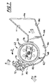
- FIG. 7 is an enlarged side elevation view of the fan taken along line 7 - 7 of FIG. 6 .
- any reference herein to the terms “left” or “right,” “forward” or “rearward,” or “top” or “bottom” are used as a matter of mere convenience, and are determined by standing at the rear of the machine facing in its normal direction of travel; use of these terms should not be construed as limiting.
- FIGS. 1 and 2 illustrate a fan assembly 10 according to the present invention arranged in operable combination with a conventional self-propelled agricultural combine harvester 12 of the axial-flow type, wherein crop material is threshed and separated while it is advanced by and along a longitudinally arranged rotor.
- a fan assembly 10 according to the present invention arranged in operable combination with a conventional self-propelled agricultural combine harvester 12 of the axial-flow type, wherein crop material is threshed and separated while it is advanced by and along a longitudinally arranged rotor.
- the self-propelled combine harvester is operatively powered by an engine (not shown) suitably housed within a body 14 of the combine harvester to provide driving power.
- the transfer of rotation and power from the engine to various driven components of the combine is of a conventional nature and could include fixed or variable belt or chain drives which are not shown for purposes of clarity.
- combine harvester 12 is provided with a conventional crop harvesting header 16 .
- the choice of header does not limit or relate to the present invention.
- the crop harvesting header 16 cuts and directs crop material into a conventional threshing apparatus 18 ( FIG. 2 ).
- the threshing apparatus includes a rotor assembly 20 , including a relatively large diameter rotor 22 that is mounted within a threshing cage 24 . Disposed about the cage 24 is a simple system of concaves 26 and separating grates 28 which, through the action of the rotor 22 and centrifugal force, act to separate grain from the straw and deliver such material to a pair of vertically spaced apart cleaning sieves 30 and 32 .
- auger 34 moves grain to the cleaning sieves 30 and 32 defining part of a cleaning area on the combine.
- U.S. Pat. No. 5,599,162 herein incorporated in its entirety by reference.
- the sieves 30 and 32 are mounted for oscillation to separate the grain from the tailings.
- the oscillation of the sieves 30 and 32 arranges the tailings received from the threshing apparatus 18 in a relatively large crop mat or veil extending across substantially the entire sieve.
- the heavier grain falls through the sieves 30 and 32 to a clean grain collector 36 .
- An auger 38 directs the grain from the collector 36 into a hopper or grain bin (not shown) often housed generally directly behind the cab 12 within combine harvester body 14 .
- Material which is too large to pass through the concaves 26 and grates 28 (chaff) is propelled rearwardly through the rotor assembly 20 .
- a conventional beater 40 acts upon the chaff discharged from the rotor assembly 20 . Beater 40 propels straw and chaff from the rear of the rotor assembly 20 and throws it back for broad discharge from the rear end of the combine.
- fan assembly 10 constructed in accordance with the present invention, is arranged in combination with the cleaning sieves 30 , 32 .
- the fan assembly 10 comprises an elongated transverse or cross flow fan 42 and an air plenum 44 .
- Fan 42 extends transversely across substantially the entire width of the combine harvester 12 . More specifically, fan 42 is transversely mounted on the combine harvester 12 beneath the threshing apparatus 18 and preferably forward of the cleaning sieves 30 , 32 .
- Air plenum 44 extends parallel to and along substantially the entire length of the fan 42 .
- the air plenum 44 is preferably fabricated from an air impervious material such as steel or the like and defines an elongated air inlet opening 62 and an elongated air outlet opening 66 . Air enters the plenum through air inlet 62 and is discharged therefrom through air outlet 66 toward the cleaning sieves 30 , 32 whereupon it passes through the sieves to carry chaff from the combine.
- the air plenum 44 wraps about and extends across the front of the fan 42 to protect the fan blades 50 from being damaged by rocks and other debris that are present in the field as the combine moves thereover.
- Air inlet 62 is bounded transversely by baffle edge 78 and inlet rotor housing 72 .
- the direction of rotation of fan 42 is from baffle edge 78 toward inlet rotor housing 72 .
- Inlet rotor 70 is rotatably disposed along rotor axis 74 within inlet rotor housing 72 which provides supportive connection to the plenum or other suitable attachment point to the combine.
- Rotor axis 74 is parallel to fan axis of rotation 48 .
- fan 42 includes a central and preferably elongated axle 46 defining an elongated axis of a rotation 48 for the fan assembly 10 , a plurality of closely spaced fan blades 50 extending axially in a circumferential array or pattern about the axis of rotation 48 to define an open center for the fan 42 , and a plurality of axially spaced and aligned fan blade mounting disks 52 .
- the mounting disks are of substantially uniform diameter.
- Each fan blade mounting disk 52 is connected to and extends radially outward from the axle 46 for driving the fan blades 50 , thereby establishing an air flow through the air plenum 44 .
- each fan blade 50 has a generally curved cross-sectional configuration and are arranged in closely spaced relation relative to each other. Each fan blade 50 preferably has a forwardly curved cross sectional configuration.
- a pair of fan blade mounting disks 52 are arranged toward opposite ends of the fan 42 . Since the length of the transverse fan 42 is functionally unlimited, other disks 52 may be provided along the length of the fan 42 to counteract centrifugal forces acting on the blades 50 during operation of the fan assembly 10 .
- each fan blade 50 is formed from a material such as sheet metal and is connected to the fan blade mounting disks 52 .
- Each fan blade support member 52 is connected to and radially extends from the axle 46 .
- FIG. 4 shows fan 42 wherein opposite ends of the fan blades 50 are arranged in general axial alignment relative to each other.
- the center portion of each fan blade 50 is, however, offset in circumferential relation relative to the opposite end thereof such that the fan blade 50 slants or tapers toward a peripheral center portion of the fan whereby each fan blade 50 has a chevron-like configuration and appearance between opposite ends thereof.
- the resultant flow of air off the blades 50 is directed outwardly toward the fan ends in a manner improving fan performance by lessening end air effects and thereby providing a generally uniform air distribution across the width of the cross-flow fan 42 .
- Angling the fan blades 52 furthermore has proven to reduce operating noise (sound) levels of the fan 42 . Accordingly, higher fan speeds can be used to increase the output flow of air from the fan 42 without concern over increasing environmental noise pollution or noise levels can be reduced for when fan speed remains unchanged.
- Fans in which fan blades 50 are arranged in a cylindrical pattern wherein the blades are in substantially parallel axial alignment with the axis of rotation 48 , that is there is no angling of the fan blades 50 are also contemplated and improved by the invention.
- inlet rotor 70 is shown extending along rotor axis 74 , including shaft 75 which is centered on the rotor axis.
- a plurality of planar blades 76 connected at one end to shaft 75 and extend in a substantially radially perpendicular direction from said shaft, ending in a distal edge 77 .
- Each planar blade 76 extends a substantially equal distance radially from shaft 75 such that the distal edges 77 define a substantially cylindrical peripheral circumference as the inlet rotor 70 rotates.
- the planar blades 76 extend axially along the axis of rotation 74 defining the length of the inlet rotor 70 , the rotor length being generally equal to the fan 42 length.
- Shaft 75 extends axially beyond the inlet rotor 70 length, with portions at each opposing end to provide a structure for rotatably connecting the inlet rotor 70 to a support structure, shown in FIG. 6 .
- eight planar blades 76 are situated in a substantially uniform radial distribution about shaft 75 .
- Other numbers of planar blades 76 are envisioned, but less than four planar blades 76 diminishes the noted advantages of the invention. Greater numbers of planar blades 76 , beyond twelve for example, increase the complexity, and therefore cost of the inlet rotor 70 without appreciable improvement in fan performance or noise reduction.
- fan 42 is supported at opposite ends by axle 46 which is rotatably mounted in bearing blocks 58 secured at opposite open ends of the air plenum 44 .
- the air plenum 44 extends parallel to and along substantially the entire length of the fan 42 .
- Inlet rotor 70 is similarly supported at opposite ends by bearings 60 so that rotor axis 74 is parallel to fan axis of rotation 48 and the outer rotor periphery is situate proximate to the circumference of fan 42 .
- the gap between the periphery of the inlet rotor 70 and the fan 42 must be sufficiently small for the inlet rotor to function as an effective fan cutoff edge. A gap of approximately six millimeters (mm) has been shown effective in one embodiment.
- inlet rotor 70 The forward portion of inlet rotor 70 is housed within an extension of air plenum 44 so that air flow from the front of the combine is directed upwardly across the face of the air plenum toward air inlet 62 without interacting with the inlet rotor 70 . As air flow curves into air inlet 62 , it interacts with the exposed planar blades 76 of the inlet rotor as it is drawn into the fan 42 , reducing air turbulence at the fan inlet cutoff and thereby reducing noise.
- inlet rotor 70 rotates freely, driven by the force of air drawing into fan inlet 62 passing planar blades 76 .
- inlet rotor 70 rotates in an opposite direction.
- a first alternative embodiment is to power the inlet rotor from the combine engine, rotating the inlet rotor 70 in a direction opposite to the direction of rotation of the fan 42 . Regardless of the method by which inlet rotor 70 is rotated, the rotation of inlet rotor 70 causes the inlet opening for fan 42 to be varied thereby avoiding disadvantages of a stationary inlet cutoff edge that leads to noise generation caused by fan operation.
- the peripheral area of the inlet rotor 70 includes more space between planar blade distal edges 77 than the planar blade distal edges 77 themselves, a passing fan blade 50 is more likely to pass a space than to interact directly with the distal edge 77 of a planar blade 76 .
- this characteristic of the rotating inlet further reduces noise levels and improves air flow uniformity along the axial length of the fan 42 .
- FIG. 7 shows a section view of air plenum 44 , fan 42 , and rotating inlet 70 .
- Air plenum 44 further defines an internal chamber 68 , wherein the fan 42 is rotatably mounted to drive air between the air inlet and air outlet opening 62 and 68 respectively.
- Plenum chamber 68 has a cross-sectional scroll-like configuration and includes an upper chamber wall 90 and a lower chamber wall 80 .
- Upper chamber wall 90 spans the width of air plenum 44 , bounded forwardly by baffle edge 78 and extending rearwardly therefrom defining the upper portion of chamber 68 to its rearwardmost edge proximal air outlet opening 66 .
- Lower chamber wall 80 includes an upstream curvilinear face 82 and a downstream curvilinear face 84 .
- Upstream face 82 of the chamber wall 80 is curved near the inlet opening 62 to meet inlet rotor housing 72 .
- Upstream face 82 and inlet rotor housing 72 smoothly merge to prevent disruption of air flow entering the fan 42 .
- Air flow direction is indicated by arrows “B” in FIG. 7 .
- the inlet rotor housing 72 wraps around a portion of inlet rotor to direct air flow around the inlet rotor to a position whereupon the air flow curves around the outer surface of plenum 44 and enters fan inlet opening 62 .
- Filler panel 85 is affixed to the outer surface of plenum 44 near the exterior juncture of inlet rotor housing 72 and upstream face 82 of air plenum 44 to further smooth air flow entering the fan.
- the contour of the forward portion inlet rotor housing 72 , filler panel 85 , and the exterior surface of the plenum 44 are sufficiently smooth so that air flow from the front of the combine is directed upwardly across the face of the air plenum 44 toward air inlet 62 without interacting with the inlet rotor 70 .
- Inlet rotor housing 72 wraps around approximately half of the inlet rotor circumference so that approximately one-fourth to one-third of the inlet rotor periphery remains exposed to the air flow entering the fan.
- Chamber wall 80 increases in distance from the periphery of fan 42 as it leads to the downstream face 84 causing air flow to be directed from the fan 42 toward the air outlet opening 66 .
- the downstream face 84 of the chamber wall 70 extends rearwardly and upwardly toward the sieves 30 , 32 for directing cleaning air exhausted from the fan 42 thereat.
Landscapes
- Engineering & Computer Science (AREA)
- Mechanical Engineering (AREA)
- General Engineering & Computer Science (AREA)
- Life Sciences & Earth Sciences (AREA)
- Environmental Sciences (AREA)
- Structures Of Non-Positive Displacement Pumps (AREA)
Abstract
Description
Claims (5)
Priority Applications (4)
| Application Number | Priority Date | Filing Date | Title |
|---|---|---|---|
| US11/479,685 US7731577B2 (en) | 2006-06-30 | 2006-06-30 | Rotating inlet for cross flow fan |
| DE602007010541T DE602007010541D1 (en) | 2006-06-30 | 2007-06-27 | Rotating inlet for a cross-flow fan |
| EP07111131A EP1872646B1 (en) | 2006-06-30 | 2007-06-27 | Rotating inlet for cross flow fan. |
| AT07111131T ATE488129T1 (en) | 2006-06-30 | 2007-06-27 | ROTATING INLET FOR A CROSS-FLOW FAN |
Applications Claiming Priority (1)
| Application Number | Priority Date | Filing Date | Title |
|---|---|---|---|
| US11/479,685 US7731577B2 (en) | 2006-06-30 | 2006-06-30 | Rotating inlet for cross flow fan |
Publications (2)
| Publication Number | Publication Date |
|---|---|
| US20080004090A1 US20080004090A1 (en) | 2008-01-03 |
| US7731577B2 true US7731577B2 (en) | 2010-06-08 |
Family
ID=38606569
Family Applications (1)
| Application Number | Title | Priority Date | Filing Date |
|---|---|---|---|
| US11/479,685 Active 2028-07-16 US7731577B2 (en) | 2006-06-30 | 2006-06-30 | Rotating inlet for cross flow fan |
Country Status (4)
| Country | Link |
|---|---|
| US (1) | US7731577B2 (en) |
| EP (1) | EP1872646B1 (en) |
| AT (1) | ATE488129T1 (en) |
| DE (1) | DE602007010541D1 (en) |
Cited By (2)
| Publication number | Priority date | Publication date | Assignee | Title |
|---|---|---|---|---|
| US20130170942A1 (en) * | 2011-12-28 | 2013-07-04 | Agco Corporation | Multiple Fan Blade Angles in a Single Crossflow Fan |
| US10201127B2 (en) * | 2016-04-15 | 2019-02-12 | Sunnybrook Welding & Machine Shop Ltd. | Air assisted thresher |
Families Citing this family (4)
| Publication number | Priority date | Publication date | Assignee | Title |
|---|---|---|---|---|
| US8221064B2 (en) | 2008-11-18 | 2012-07-17 | Cnh America Llc | Transverse fan assembly having a supplementary air feed inlet for infill of air flow deficiencies to effect a desired output air flow pattern, and method of use thereof |
| CN105723956A (en) * | 2016-03-22 | 2016-07-06 | 湖南省农广农业装备有限公司 | External air suction grain cleaning device |
| US10561069B2 (en) * | 2017-10-06 | 2020-02-18 | Cnh Industrial America Llc | Segmented fan housing for cleaning system of combine harvester |
| RU203206U1 (en) * | 2019-06-07 | 2021-03-25 | Открытое акционерное общество "Гомсельмаш" | CENTRIFUGAL FAN CLEANING SYSTEM GRAIN HARVESTER |
Citations (14)
| Publication number | Priority date | Publication date | Assignee | Title |
|---|---|---|---|---|
| US2057403A (en) | 1933-11-20 | 1936-10-13 | Vali John Eddie | Loading and unloading machine |
| US3096931A (en) | 1960-05-28 | 1963-07-09 | Eck Bruno | Cross flow fan arrangement |
| US3116238A (en) | 1961-10-02 | 1963-12-31 | Griffin Ind Inc | Centrifugal classifier |
| US3150816A (en) * | 1962-09-05 | 1964-09-29 | Laing Nikolaus | Cross-flow fluid machine having counterrotating rotors |
| US3152876A (en) * | 1959-04-28 | 1964-10-13 | Laing Nikolaus | Laundry drier |
| US3161348A (en) * | 1957-12-09 | 1964-12-15 | Laing Nikolaus | High-output blower |
| US3238725A (en) | 1962-09-05 | 1966-03-08 | Ludin Ludwig | Pump and turbine fluid drive unit |
| US3322332A (en) | 1962-09-05 | 1967-05-30 | Laing Vortex Inc | Cross flow machine |
| US3840022A (en) * | 1972-05-16 | 1974-10-08 | Deere & Co | Combine blower |
| US4251356A (en) | 1978-02-06 | 1981-02-17 | Hauni-Werke Korber & Co., Kg | Apparatus for classifying the constituents of a pneumatically conveyed tobacco-containing stream |
| US4869272A (en) * | 1988-05-02 | 1989-09-26 | J. I. Case Company | Cleaning system for combines |
| EP0489672A1 (en) * | 1990-12-04 | 1992-06-10 | Air Technic | Double flow ventilation unit, particularly for a technical compartment |
| US5421147A (en) | 1993-07-29 | 1995-06-06 | Fr Mfg. Corporation | Nut harvester |
| US6341643B1 (en) | 1999-05-10 | 2002-01-29 | Denso Corporation | Crossflow fan |
Family Cites Families (10)
| Publication number | Priority date | Publication date | Assignee | Title |
|---|---|---|---|---|
| GB479823A (en) * | 1936-06-01 | 1938-02-11 | British Thomson Houston Co Ltd | Improvements in and relating to centrifugal fans |
| DE1130643B (en) * | 1960-04-08 | 1962-05-30 | Helmut Claas Dipl Ing | Cleaning blowers in threshing machines, in particular in combine harvesters |
| US3223313A (en) * | 1964-02-04 | 1965-12-14 | Lau Blower Co | Air moving device |
| GB1293553A (en) * | 1969-02-18 | 1972-10-18 | Cav Ltd | Radial flow fans |
| US4906219A (en) * | 1988-08-15 | 1990-03-06 | J. I. Case Company | Cleaning system for a combine |
| JPH04183993A (en) * | 1990-11-16 | 1992-06-30 | Matsushita Electric Ind Co Ltd | Cross flow fan |
| US5599162A (en) * | 1995-08-09 | 1997-02-04 | Case Corporation | Transverse blower fan assembly |
| US5573369A (en) * | 1995-11-08 | 1996-11-12 | The Scott Fetzer Company | Impeller for vacuum cleaner with tapered blades |
| US6514036B2 (en) * | 2001-04-27 | 2003-02-04 | Black & Decker Inc. | Radial flow fan with impeller having blade configuration for noise reduction |
| JP4426776B2 (en) * | 2003-04-25 | 2010-03-03 | 株式会社やまびこ | Centrifugal impeller for ventilation |
-
2006
- 2006-06-30 US US11/479,685 patent/US7731577B2/en active Active
-
2007
- 2007-06-27 AT AT07111131T patent/ATE488129T1/en not_active IP Right Cessation
- 2007-06-27 DE DE602007010541T patent/DE602007010541D1/en active Active
- 2007-06-27 EP EP07111131A patent/EP1872646B1/en active Active
Patent Citations (14)
| Publication number | Priority date | Publication date | Assignee | Title |
|---|---|---|---|---|
| US2057403A (en) | 1933-11-20 | 1936-10-13 | Vali John Eddie | Loading and unloading machine |
| US3161348A (en) * | 1957-12-09 | 1964-12-15 | Laing Nikolaus | High-output blower |
| US3152876A (en) * | 1959-04-28 | 1964-10-13 | Laing Nikolaus | Laundry drier |
| US3096931A (en) | 1960-05-28 | 1963-07-09 | Eck Bruno | Cross flow fan arrangement |
| US3116238A (en) | 1961-10-02 | 1963-12-31 | Griffin Ind Inc | Centrifugal classifier |
| US3238725A (en) | 1962-09-05 | 1966-03-08 | Ludin Ludwig | Pump and turbine fluid drive unit |
| US3150816A (en) * | 1962-09-05 | 1964-09-29 | Laing Nikolaus | Cross-flow fluid machine having counterrotating rotors |
| US3322332A (en) | 1962-09-05 | 1967-05-30 | Laing Vortex Inc | Cross flow machine |
| US3840022A (en) * | 1972-05-16 | 1974-10-08 | Deere & Co | Combine blower |
| US4251356A (en) | 1978-02-06 | 1981-02-17 | Hauni-Werke Korber & Co., Kg | Apparatus for classifying the constituents of a pneumatically conveyed tobacco-containing stream |
| US4869272A (en) * | 1988-05-02 | 1989-09-26 | J. I. Case Company | Cleaning system for combines |
| EP0489672A1 (en) * | 1990-12-04 | 1992-06-10 | Air Technic | Double flow ventilation unit, particularly for a technical compartment |
| US5421147A (en) | 1993-07-29 | 1995-06-06 | Fr Mfg. Corporation | Nut harvester |
| US6341643B1 (en) | 1999-05-10 | 2002-01-29 | Denso Corporation | Crossflow fan |
Cited By (2)
| Publication number | Priority date | Publication date | Assignee | Title |
|---|---|---|---|---|
| US20130170942A1 (en) * | 2011-12-28 | 2013-07-04 | Agco Corporation | Multiple Fan Blade Angles in a Single Crossflow Fan |
| US10201127B2 (en) * | 2016-04-15 | 2019-02-12 | Sunnybrook Welding & Machine Shop Ltd. | Air assisted thresher |
Also Published As
| Publication number | Publication date |
|---|---|
| US20080004090A1 (en) | 2008-01-03 |
| DE602007010541D1 (en) | 2010-12-30 |
| ATE488129T1 (en) | 2010-12-15 |
| EP1872646B1 (en) | 2010-11-17 |
| EP1872646A1 (en) | 2008-01-02 |
Similar Documents
| Publication | Publication Date | Title |
|---|---|---|
| US8052374B2 (en) | Cut-off construction for transverse fan assemblies that have elongated fan blades of arcuate cross-section | |
| US6699121B2 (en) | Comminuting device in an agricultural harvesting machine | |
| US8221064B2 (en) | Transverse fan assembly having a supplementary air feed inlet for infill of air flow deficiencies to effect a desired output air flow pattern, and method of use thereof | |
| EP3143866B1 (en) | A system for chopping and spreading residue | |
| US7104883B2 (en) | Straw chopper blade | |
| US4906219A (en) | Cleaning system for a combine | |
| US7731577B2 (en) | Rotating inlet for cross flow fan | |
| US5599162A (en) | Transverse blower fan assembly | |
| EP1872647B1 (en) | Chevron inlet for cross flow fan | |
| CA2554178C (en) | Straw chopper with fan having enhanced air flow in an agricultural combine | |
| US6296566B1 (en) | Infeed impeller for a rotary combine | |
| US20090163260A1 (en) | Combine harvester having blower for pneumatic cleaning | |
| JPS60256310A (en) | Grain scraping rotor of harvester | |
| US6979261B1 (en) | Dust reducing airflow diverter for combine | |
| US6908378B2 (en) | Threshing rotor inlet flight extension | |
| US6830512B2 (en) | Shroud for the infeed impeller of a rotary combine | |
| EP3414990B1 (en) | Cleaning shoe venting through chopper rotor assembly | |
| US11812701B2 (en) | Tangential feeding to a threshing rotor | |
| CA2373948A1 (en) | Flail straw chopper blade | |
| US7166025B2 (en) | Combine threshing rotor front bearing and inlet section with anti-wind features | |
| US20080194305A1 (en) | Bearing assembly and cleaning system in combine harvesters | |
| CA2007203C (en) | Cleaning system for a combine | |
| JP2005218393A (en) | Ordinary-type combine |
Legal Events
| Date | Code | Title | Description |
|---|---|---|---|
| AS | Assignment |
Owner name: CNH AMERICA, LLC, PENNSYLVANIA Free format text: ASSIGNMENT OF ASSIGNORS INTEREST;ASSIGNOR:RICKETTS, JON E.;REEL/FRAME:017956/0263 Effective date: 20060629 Owner name: CNH AMERICA, LLC,PENNSYLVANIA Free format text: ASSIGNMENT OF ASSIGNORS INTEREST;ASSIGNOR:RICKETTS, JON E.;REEL/FRAME:017956/0263 Effective date: 20060629 |
|
| STCF | Information on status: patent grant |
Free format text: PATENTED CASE |
|
| AS | Assignment |
Owner name: BLUE LEAF I.P., INC., DELAWARE Free format text: ASSIGNMENT OF ASSIGNORS INTEREST;ASSIGNOR:CNH AMERICA LLC;REEL/FRAME:025105/0143 Effective date: 20101007 |
|
| FPAY | Fee payment |
Year of fee payment: 4 |
|
| MAFP | Maintenance fee payment |
Free format text: PAYMENT OF MAINTENANCE FEE, 8TH YEAR, LARGE ENTITY (ORIGINAL EVENT CODE: M1552) Year of fee payment: 8 |
|
| MAFP | Maintenance fee payment |
Free format text: PAYMENT OF MAINTENANCE FEE, 12TH YEAR, LARGE ENTITY (ORIGINAL EVENT CODE: M1553); ENTITY STATUS OF PATENT OWNER: LARGE ENTITY Year of fee payment: 12 |