US7730693B2 - Decking system - Google Patents
Decking system Download PDFInfo
- Publication number
- US7730693B2 US7730693B2 US10/840,957 US84095704A US7730693B2 US 7730693 B2 US7730693 B2 US 7730693B2 US 84095704 A US84095704 A US 84095704A US 7730693 B2 US7730693 B2 US 7730693B2
- Authority
- US
- United States
- Prior art keywords
- stiffening members
- bead
- clips
- free end
- along
- Prior art date
- Legal status (The legal status is an assumption and is not a legal conclusion. Google has not performed a legal analysis and makes no representation as to the accuracy of the status listed.)
- Expired - Fee Related, expires
Links
- 239000011324 bead Substances 0.000 claims abstract description 42
- 239000000758 substrate Substances 0.000 claims description 17
- 230000002093 peripheral effect Effects 0.000 claims description 7
- 239000000853 adhesive Substances 0.000 claims description 2
- 230000001070 adhesive effect Effects 0.000 claims description 2
- 238000004519 manufacturing process Methods 0.000 abstract description 2
- 239000000463 material Substances 0.000 description 17
- 238000000034 method Methods 0.000 description 8
- 230000008602 contraction Effects 0.000 description 4
- 238000009408 flooring Methods 0.000 description 3
- 238000012986 modification Methods 0.000 description 3
- 230000004048 modification Effects 0.000 description 3
- 239000002023 wood Substances 0.000 description 3
- 239000004566 building material Substances 0.000 description 2
- 238000001125 extrusion Methods 0.000 description 2
- 238000002347 injection Methods 0.000 description 2
- 239000007924 injection Substances 0.000 description 2
- 238000001746 injection moulding Methods 0.000 description 2
- 239000000203 mixture Substances 0.000 description 2
- 239000004698 Polyethylene Substances 0.000 description 1
- 229910000831 Steel Inorganic materials 0.000 description 1
- XAGFODPZIPBFFR-UHFFFAOYSA-N aluminium Chemical compound [Al] XAGFODPZIPBFFR-UHFFFAOYSA-N 0.000 description 1
- 229910052782 aluminium Inorganic materials 0.000 description 1
- 238000005266 casting Methods 0.000 description 1
- 239000004927 clay Substances 0.000 description 1
- 238000007796 conventional method Methods 0.000 description 1
- 230000001627 detrimental effect Effects 0.000 description 1
- 239000000428 dust Substances 0.000 description 1
- 238000005242 forging Methods 0.000 description 1
- 238000003754 machining Methods 0.000 description 1
- 239000011120 plywood Substances 0.000 description 1
- -1 polyethylene Polymers 0.000 description 1
- 229920000573 polyethylene Polymers 0.000 description 1
- 229920000642 polymer Polymers 0.000 description 1
- 229920002635 polyurethane Polymers 0.000 description 1
- 239000004814 polyurethane Substances 0.000 description 1
- 229920000915 polyvinyl chloride Polymers 0.000 description 1
- 239000004800 polyvinyl chloride Substances 0.000 description 1
- 230000005855 radiation Effects 0.000 description 1
- 239000010959 steel Substances 0.000 description 1
- 239000004575 stone Substances 0.000 description 1
- 229920002554 vinyl polymer Polymers 0.000 description 1
- 239000002983 wood substitute Substances 0.000 description 1
Images


Classifications
-
- E—FIXED CONSTRUCTIONS
- E04—BUILDING
- E04F—FINISHING WORK ON BUILDINGS, e.g. STAIRS, FLOORS
- E04F15/00—Flooring
- E04F15/02—Flooring or floor layers composed of a number of similar elements
- E04F15/10—Flooring or floor layers composed of a number of similar elements of other materials, e.g. fibrous or chipped materials, organic plastics, magnesite tiles, hardboard, or with a top layer of other materials
-
- E—FIXED CONSTRUCTIONS
- E04—BUILDING
- E04F—FINISHING WORK ON BUILDINGS, e.g. STAIRS, FLOORS
- E04F2201/00—Joining sheets or plates or panels
- E04F2201/05—Separate connectors or inserts, e.g. pegs, pins, keys or strips
- E04F2201/0517—U- or C-shaped brackets and clamps
-
- E—FIXED CONSTRUCTIONS
- E04—BUILDING
- E04F—FINISHING WORK ON BUILDINGS, e.g. STAIRS, FLOORS
- E04F2201/00—Joining sheets or plates or panels
- E04F2201/05—Separate connectors or inserts, e.g. pegs, pins, keys or strips
- E04F2201/0594—Hinge-like connectors
-
- F—MECHANICAL ENGINEERING; LIGHTING; HEATING; WEAPONS; BLASTING
- F16—ENGINEERING ELEMENTS AND UNITS; GENERAL MEASURES FOR PRODUCING AND MAINTAINING EFFECTIVE FUNCTIONING OF MACHINES OR INSTALLATIONS; THERMAL INSULATION IN GENERAL
- F16B—DEVICES FOR FASTENING OR SECURING CONSTRUCTIONAL ELEMENTS OR MACHINE PARTS TOGETHER, e.g. NAILS, BOLTS, CIRCLIPS, CLAMPS, CLIPS OR WEDGES; JOINTS OR JOINTING
- F16B2200/00—Constructional details of connections not covered for in other groups of this subclass
- F16B2200/30—Dovetail-like connections
Definitions
- This invention relates to building materials.
- the invention concerns an improved panel system, and more particularly the invention relates to a panel system for use as flooring or decking.
- building materials consist of various forms of natural resources, such as stone, wood, and clay. More recently, man-made materials have been introduced. There has been an increase on the demand for man-made materials substituting polymeric materials for wood products. Certain companies have combined a mixture of polymers and wood chips and/or dust and extruded this mixture to form long planks. Once cured, these planks have been used as decking materials and at times used for outdoor furniture.
- a major disadvantage associated with these types of wood substitutes is the coefficients of expansion and contraction for the polymeric material. Often, the expansion and contraction is so substantial that the planks buckle and/or leave substantial gaps from shrinkage.
- the purpose of this invention is to provide a polymeric decking system that accommodates the shrinkage and expansion of the polymeric material produced by changes in temperature.
- a floor panel assembly having a tabular sheet defined by an upper surface, a lower surface, and a common peripheral edge. At least two spaced apart stiffening members extend from the lower surface and run substantially the length of the tabular sheet. A bead is defined along a free edge of one stiffening member while a tab extends from the free edge of the opposite stiffening member.
- a plurality of clips are included, each of which is adapted to be fastened to a substrate and receive a one of the free edges in locking relationship for holding said tabular sheet in position.
- the two stiffening members extending from said lower surface of the tabular sheet and having the bead and tab preferably have a height less than other stiffening members to account for the height of the mounting clips.
- a plurality of spacing bosses are defined at predetermined intervals along the length of one of the bead and tab. The bosses restrict the longitudinal movement of each panel during periods of expansion and contraction.
- a tapered flange is located at one end of each panel.
- a corresponding recess is defined in the opposite end of another panel to receive the tapered flange.
- a finishing panel is provided having a vertical member depending from the lower surface proximate one end and at an angle to the stiffening members.
- each of the clips include a dedicated recess for receiving a respective one of the bead and the tab at the ends of the stiffening members. Moreover, on each of the plurality of clips, the recess for the tab is outboard of the recess for said bead. In the alternative, and depending upon the desired configuration the dedicated recess for the bead is outboard of the recess for the tab.
- a decking system comprising a plurality of decking panels adapted to be arranged in a predetermined array over a predetermined substrate.
- Each of the plurality of decking panels includes an upper surface of predetermined extant and an opposing lower surface of substantially equal extant joined to the upper surface by a shared peripheral edge.
- At least two, spaced apart, and generally parallel stiffening members are defined extending from the lower surface and run substantially along the length of each panel to provide structural rigidity.
- One of the stiffening members includes a bead of predetermined geometric cross-section defined along a free edge.
- the opposite one of the stiffening members includes a projection defined along a free edge thereof to assist in fixing the relative position of each panel.
- Mounting is actually accomplished by a plurality of clips, each constructed to be rigidly fixed to the substrate and receive one of the bead and the projection extending from one of the stiffening members.
- a plurality of spacing bosses are spaced at predetermined intervals along one of the bead and the projection.
- a third stiffening member extends from the lower surface and is positioned intermediate the two stiffening members mentioned earlier.
- One end of each panel terminates in a tapered flange.
- the opposite end of each panel includes a recess for receiving the tapered flange of another panel.
- a method for manufacturing the decking or floor panel comprises the steps of producing a panel of predetermined dimension with an upper surface and a lower surface sharing a common peripheral edge. At least two spaced apart stiffening members are defined extending substantially perpendicular from the lower surface of said panel. The method further includes the steps of forming one of a bead and a projection along a free edge of one of the stiffening members, and an opposite one of the bead and projection on a free edge of the other stiffening member.
- a further embodiment of the method includes forming a tapered flange at one end of the panel which adapted to be received within a recess formed at an opposite end of another panel.
- the tapered flange is formed in a manner to automatically space the end of one panel from the end of an adjoining panel.
- each of the panels is formed using one of the methods of injection molding, extrusion molding, machining, forging and casting.
- the plurality of clips are formed separate and apart from the panels so that each is configured to be anchored to a substrate.
- Each of the clips is formed with a plurality of attachment members adapted to receive a respective one of the bead and the projection to retain the panel to the substrate.
- the method further comprises forming a plurality of spacing bosses at predetermined intervals along one of the bead and the projection. To help provide longitudinal stability, each clip is adapted to be received between a pair of spacing bosses.
- FIG. 1 is a fragmentary plan view illustrating one possible pattern for the planking material of this invention
- FIG. 2 is a side elevational view of one embodiment of a panel of the invention
- FIG. 3 is an end elevational view of the panel shown in FIG. 2 ;
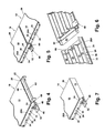
- FIG. 4 is a fragmentary oblique view of one end of a panel of the invention.
- FIG. 5 is a fragmentary oblique view illustrating adjoining ends of panels
- FIG. 6 is a fragmentary oblique view illustrating the underside of two adjacent end panels
- FIG. 7 is a fragmentary oblique view illustrating an end or cap wall of a panel of the invention.
- FIGS. 8 a , 8 b , 8 c , and 8 d schematically illustrate assembly relationships between laterally adjacent panels of the invention.
- the terms “upper,” “lower,” “left,” “rear,” “front,” “vertical,” “horizontal” and derivatives of such terms shall relate to the invention as oriented in FIGS. 2 and 3 .
- the invention may assume various alternative orientations, except where expressly specified to the contrary.
- the specific devices and processes illustrated in the attached drawings, and described in the following specification are simply exemplary embodiments of the inventive concepts defined in the inventive concepts of this invention. Specific dimensions and other physical characteristics relating to the embodiments disclosed herein are not to be considered as limiting unless expressly stated otherwise.
- the instant invention comprises an improved decking and flooring material in the form of three dimensional tabular sheets or planks 10 having a length substantially greater than its width which in turn is substantially greater than the thickness.
- each of the tabular sheets may be formed using one of injection molding and extrusion of a polymeric material.
- FIGS. 1 through 3 illustrating an injection molded polymeric structure having a length (L) on the order of 48 inches, a width (W) of approximately 6 inches, and a height (H) ranging between 1 and 11 ⁇ 2 inches.
- a number of panels 10 are assembled together to form a panel assembly 12 .
- each of the tabular sheets or planks 10 are arranged longitudinally adjacent each other and supported by perpendicularly arranged joists 14 spaced at predetermined intervals or other suitable substrate.
- the spacing between the joists 14 has been established at 16 inches-on-center.
- the joists 14 are spaced 16 inches-on-center, the spacing may be changed depending in large part upon the length of each of the tabular sheets or planks 10 .
- other suitable substrates may include steel or aluminum beams, plywood sheeting, concrete or other stable surface.
- FIGS. 2 and 3 generally illustrate one embodiment of structural features in each tabular sheet or plank 10 .
- each tabular sheet or plank 10 is preferably injection molded or extruded from a polymeric material.
- a polymeric material includes polyvinyl chloride, although other materials may also be used so long as they provide stability to ultra violet radiation and maintains their integrity at hot and cold temperatures.
- each plank 10 contains an upper surface 16 , a lower surface 18 and a plurality of longitudinal stiffening members 20 , each extending substantially perpendicular from the lower surface 18 .
- Outboard of longitudinal stiffening members 20 are plank sidewalls 22 and 24 which also extend the length of each plank. As best illustrated in FIG.
- sidewall 22 depends from the lower surface 18 substantially at the peripheral edge 26 of surfaces 16 and 18 .
- the vertical height (H) of sidewall 22 is slightly less than that of the inboard longitudinal stiffening members 20 for reasons which will become immediately apparent below.
- the lower terminal edge of sidewall 22 includes a lateral extension running the length of the sidewall 22 defined by a shoulder 28 and tapered vertical wall 30 to define a tab structure.
- the sidewall 24 extending downwardly from lower surface 18 on the opposite side of the plank 10 is offset laterally inward from the peripheral edge 26 a of surfaces 16 and 18 .
- the lower end of sidewall 22 terminates in a longitudinal bead 32 which extends substantially along the length of the plank 10 .
- the particular transverse form of longitudinal bead 32 may vary so long as the requisite function is performed.
- the bead may be in the form of a substantially linear post, a polygon, or even an oval or circle.
- each spacing boss 36 Spaced periodically along the outer surface 34 of sidewall 24 and extending from the upper portion of the bead 32 onto the sidewall 24 is a spacing boss 36 .
- the distance between each spacing boss 36 is narrowest toward a transverse middle portion of each panel, and increases as one moves toward one of the opposing ends of the plank 10 .
- the distance between the spacing bosses 36 at the center of the plank may be on the order of one inch and on the order of one and one-half inch at the ends of the plank 10 .
- Each plank 10 is anchored to the underlying joist 14 by a plurality of clips 40 generally identified by reference numeral 40 .
- Each clip 40 is substantially tabular in shape with a substantially cylindrical recess 42 extending along edge 44 .
- a second recess 46 defined by inclined wall 48 and shoulder 50 .
- Spaced from the recesses 42 and 46 , and proximate the opposing edge 52 are one or more perforations 54 for receiving a screw, nail, or other anchor for attaching the clip 40 to the joists 14 .
- Additional attachment methods for rigidly attaching each of the plurality of clips may include one of a screw, a rivet, a bolt, an adhesive, a clamp, and a pinch flange.
- each clip 40 is substantially the same, and slightly less than the minimal distance between the spacing bosses 36 . In particular, for the example described above, it is preferred that the width of the clip 40 be less than one inch.
- a plurality of clips 40 are used to anchor each plank 10 to the joist 14 by sidewall 22 and shoulder 28 received within the recess 46 to engage shoulder 50 , thus keeping that portion of plank 10 securely anchored against the joist 14 .
- the longitudinal bead 32 is received within the recesses 42 of each of the plurality of clips 40 spaced along the length of each plank and anchored to the underlying joist 14 .
- the recess 42 in turn is received in snap fit arrangement around the bead 32 to retain the sidewall 24 against the joists 14 .
- the difference in height between the longitudinal stiffening members 20 and the outboard sidewalls 22 and 24 are compensated by the thickness of the tabular portions of the clips 40 .
- the spacing between the recess 46 and the cylindrical recess 42 are such that outside wall 22 may be positioned in a fixed spaced relationship with respect to sidewall 24 of the adjacent plank 10 to ensure even spacing between the adjoining planks.
- the distance between each of the spacing bosses 36 and the clips 40 provides adequate room for each plank to expand and contract in a direction parallel to the longitudinal axis.
- a first end 60 of each plank 10 includes a tapered flange 62 positioned slightly lower than the upper surface 16 and slightly inboard of each sidewall 22 , 24 .
- Each tapered flange 62 is dimensioned to be received within a dimensionally close fitting recess 64 defined in the second end 66 of the adjacent plank 10 .
- the dimension of the tapered flange 62 is sufficient to continue to span the gap between adjacent planks 10 when each plank 10 has retracted to its maximum extent in cold weather, and more than adequate to span the distance when each plank has reached its maximum point of expansion.
- Appropriate spacing between the ends of the respective planks 10 is automatically provided by a tab 68 molded onto the tapered flange 62 to space the first end 60 relative to the second end 66 .
- FIG. 7 illustrates one embodiment of a finished end of a plank 72 to be used at the exposed edges of the deck or flooring planks 10 .
- the finished edge of each finishing plank 72 is provided by an end or cap wall 70 interconnecting the sidewalls 22 and 24 at one end of the finishing plank. Additional planks 72 provided with the finished end will cover the second end of the plank 10 so that both ends of a series of interconnected planks have a finished professional look.
- end caps or finishing planks 72 may be formed to provide angled faces 70 . The range of available angled ends can be provided to cover a predetermined combination of angle orientations.
- FIG. 8 a through FIG. 8 d generally illustrate the method for assembling a floor or deck assembly using the instant invention.
- a first plank 10 is initially fit with a plurality of clips 40 by positioning the longitudinal bead 32 at the end of sidewall 24 adjacent the cylindrical recess 42 in the clip 40 .
- the bead 32 is forced into the recess 42 under pressure.
- the clip 40 is then automatically centered within the space between adjacent spacing bosses 36 by shoulder 50 engaging the bosses 36 and being urged into the space between the bosses.
- the clip 40 With the tab clip 40 attached to the sidewall 24 , the clip 40 is placed at the appropriate location on the joist 14 so the plank 10 is properly aligned and anchored with a fastener such as one of those described above and identified by reference numeral 76 .
- the immediately adjacent plank 10 is then positioned by inserting the sidewall 22 into the recess 46 of the clip 40 so that the shoulder 28 engages the shoulder 50 .
- the pressure exerted against the interior of sidewall 22 by the inclined wall 48 ensures engagement of the respective shoulders to lock the sidewall 22 into clip 40 (see FIG. 8 d ).
- the lateral and longitudinal spacing of the planks 10 with respect to each other and the manner using the clips 40 provides sufficient room for expansion and contraction of the material as a result in change of temperature.
- the variation in spacing between the bosses 36 along each plank 10 ensures that the distances and gaps between adjacent planks will be accommodated substantially uniformly to prevent any major gaps between the plank, or excessive buckling between the ends which would be detrimental to the appearance of the surface formed by the planks 10 .
- each of the planks 10 and the clips 40 be formed from a polymeric material using conventional techniques.
- the polymeric material may be a polyurethane, polyethylene, or polyvinyl material. In some cases and applications other polymeric materials may be used to work suitably within different environments.
- a certain crown may be formed on the upper surface 16 to improve the runoff of moisture or debris from the plank surface 16 .
Landscapes
- Engineering & Computer Science (AREA)
- Architecture (AREA)
- Civil Engineering (AREA)
- Structural Engineering (AREA)
- Floor Finish (AREA)
Abstract
Description
Claims (16)
Priority Applications (1)
| Application Number | Priority Date | Filing Date | Title |
|---|---|---|---|
| US10/840,957 US7730693B2 (en) | 2003-05-09 | 2004-05-07 | Decking system |
Applications Claiming Priority (2)
| Application Number | Priority Date | Filing Date | Title |
|---|---|---|---|
| US46947703P | 2003-05-09 | 2003-05-09 | |
| US10/840,957 US7730693B2 (en) | 2003-05-09 | 2004-05-07 | Decking system |
Publications (2)
| Publication Number | Publication Date |
|---|---|
| US20050039413A1 US20050039413A1 (en) | 2005-02-24 |
| US7730693B2 true US7730693B2 (en) | 2010-06-08 |
Family
ID=34197765
Family Applications (1)
| Application Number | Title | Priority Date | Filing Date |
|---|---|---|---|
| US10/840,957 Expired - Fee Related US7730693B2 (en) | 2003-05-09 | 2004-05-07 | Decking system |
Country Status (1)
| Country | Link |
|---|---|
| US (1) | US7730693B2 (en) |
Cited By (13)
| Publication number | Priority date | Publication date | Assignee | Title |
|---|---|---|---|---|
| US8322103B1 (en) * | 2008-10-22 | 2012-12-04 | Charles D Kownacki | Faux brick with suspension system |
| US20140245685A1 (en) * | 2013-03-04 | 2014-09-04 | Bernardus Hendrikus Wielens | Building and mounting system |
| US9200445B2 (en) | 2013-09-25 | 2015-12-01 | Richard Alan Leines | Dual fitting plank and clip system |
| US9534377B2 (en) | 2011-07-30 | 2017-01-03 | Earl Lee | Deck preservation system |
| US20170130465A1 (en) * | 2014-09-08 | 2017-05-11 | Mark Claudin | Deck installation track and method |
| US20190249424A1 (en) * | 2013-10-25 | 2019-08-15 | Mbrico, Llc | Tile and Support Structure |
| USD879329S1 (en) * | 2016-09-13 | 2020-03-24 | Solutions Murales Proslat Inc. | Slatwall panel |
| US10934714B1 (en) | 2013-10-25 | 2021-03-02 | Mbrico, Llc | Tile and support structure |
| US10988931B1 (en) | 2013-10-25 | 2021-04-27 | Mbrico, Llc | Tile and support structure |
| US11199007B2 (en) | 2013-10-25 | 2021-12-14 | Mbrico, Llc | Tile and support structure |
| US11371245B2 (en) | 2013-10-25 | 2022-06-28 | Mbrico, Llc | Tile and support structure |
| US11982087B2 (en) | 2019-05-17 | 2024-05-14 | Mbrico, Llc | Tile and support structure |
| US20240301695A1 (en) * | 2013-10-25 | 2024-09-12 | Mbrico, Llc | Stone or porcelain tile |
Families Citing this family (10)
| Publication number | Priority date | Publication date | Assignee | Title |
|---|---|---|---|---|
| US6935628B1 (en) | 2004-07-26 | 2005-08-30 | Carl Conversa | Clamp jaw |
| US7610731B1 (en) * | 2005-01-10 | 2009-11-03 | Comc, Llc | Snap together floor structure |
| US7543417B2 (en) | 2005-10-04 | 2009-06-09 | Comc, Llc | Modular flooring assemblies |
| US7926239B2 (en) * | 2006-03-31 | 2011-04-19 | Columbia Insurance Company | Flooring profile |
| US8261507B2 (en) * | 2006-05-12 | 2012-09-11 | Columbia Insurance Company | Flooring profile |
| US20080078135A1 (en) * | 2006-10-03 | 2008-04-03 | Mcintosh Jonathan | Grout member for modular flooring assemblies |
| US8230654B2 (en) | 2009-06-10 | 2012-07-31 | Comc, Llc | Medallion insert for modular flooring assemblies |
| US8782989B2 (en) | 2009-06-11 | 2014-07-22 | Comc, Llc | Narrow lined modular flooring assemblies |
| US8474196B2 (en) | 2011-10-10 | 2013-07-02 | Cameron Marriott | Modular decking system |
| GB2596788B (en) | 2020-06-29 | 2024-09-04 | Ryno Ltd | Decking clip and decking assembly comprising a decking clip |
Citations (22)
| Publication number | Priority date | Publication date | Assignee | Title |
|---|---|---|---|---|
| US3528391A (en) * | 1968-09-18 | 1970-09-15 | Reynolds Metals Co | Floor construction for an animal enclosure and method of making same |
| US3722473A (en) * | 1971-08-13 | 1973-03-27 | Reynolds Metals Co | Floor construction and member for making same |
| US4077334A (en) * | 1976-07-30 | 1978-03-07 | Extrados Company Limited | Pallet construction |
| US4078515A (en) * | 1977-04-06 | 1978-03-14 | Extrados Company Limited | Dock structure |
| US4703597A (en) * | 1985-06-28 | 1987-11-03 | Eggemar Bengt V | Arena floor and flooring element |
| US5048448A (en) | 1989-12-15 | 1991-09-17 | Ctb, Inc. | Boat dock structure |
| US5553427A (en) | 1995-03-01 | 1996-09-10 | Thermal Industries, Inc. | Plastic extrusions for use in floor assemblies |
| US5735097A (en) * | 1996-12-16 | 1998-04-07 | Cheyne; Donald C. | Platform assembly system |
| US5881508A (en) * | 1997-10-15 | 1999-03-16 | Materials International, Inc. | Decking extrusion |
| US5950377A (en) * | 1996-08-09 | 1999-09-14 | Royal Crown Limited | Deck structure |
| US5953878A (en) | 1997-06-06 | 1999-09-21 | S.S.D. Control Technology, Inc. | Polyvinyl deck |
| US6112479A (en) | 1998-06-01 | 2000-09-05 | Thermal Industries, Inc. | Floor assembly having an extrusion and snap connector |
| US6233886B1 (en) * | 1999-03-23 | 2001-05-22 | Thermal Industries, Inc. | Floor assembly and associated method of making a floor assembly |
| US6314699B1 (en) | 1999-01-15 | 2001-11-13 | Kroy Building Products, Inc. | Deck system with deck clip |
| US6324796B1 (en) | 2000-04-10 | 2001-12-04 | Homeland Vinyl Products, Inc. | Modular decking planks |
| US20020056238A1 (en) | 2000-05-20 | 2002-05-16 | Leines Richard Alan | Deck plank extrusion and retaining clip |
| US20020059766A1 (en) | 1999-07-19 | 2002-05-23 | Gregori Karl H. W. | Decking assembly and decking kit with hold-down clip |
| US20030009973A1 (en) * | 2001-07-12 | 2003-01-16 | Chiu-Ying Lee | Wood floor assembly |
| US20030101673A1 (en) | 1999-01-15 | 2003-06-05 | Kroy Building Products, Inc. | Deck system with deck clip |
| US6584748B2 (en) * | 2000-02-25 | 2003-07-01 | Mary Bresnahan | Deck covering system |
| US6637163B2 (en) * | 2001-07-25 | 2003-10-28 | Gt Plastics Inc. | Decking |
| US20040079041A1 (en) | 2002-10-25 | 2004-04-29 | Bruno Bergeron | Floor assemblies including a number of structural elongated flooring members extending across transverse supports |
-
2004
- 2004-05-07 US US10/840,957 patent/US7730693B2/en not_active Expired - Fee Related
Patent Citations (27)
| Publication number | Priority date | Publication date | Assignee | Title |
|---|---|---|---|---|
| US3528391A (en) * | 1968-09-18 | 1970-09-15 | Reynolds Metals Co | Floor construction for an animal enclosure and method of making same |
| US3722473A (en) * | 1971-08-13 | 1973-03-27 | Reynolds Metals Co | Floor construction and member for making same |
| US4077334A (en) * | 1976-07-30 | 1978-03-07 | Extrados Company Limited | Pallet construction |
| US4078515A (en) * | 1977-04-06 | 1978-03-14 | Extrados Company Limited | Dock structure |
| US4703597A (en) * | 1985-06-28 | 1987-11-03 | Eggemar Bengt V | Arena floor and flooring element |
| US5048448A (en) | 1989-12-15 | 1991-09-17 | Ctb, Inc. | Boat dock structure |
| US5553427A (en) | 1995-03-01 | 1996-09-10 | Thermal Industries, Inc. | Plastic extrusions for use in floor assemblies |
| US5642592A (en) | 1995-03-01 | 1997-07-01 | Thermal Industries, Inc. | Plastic extrusions for use in floor assemblies |
| US5950377A (en) * | 1996-08-09 | 1999-09-14 | Royal Crown Limited | Deck structure |
| US5735097A (en) * | 1996-12-16 | 1998-04-07 | Cheyne; Donald C. | Platform assembly system |
| US5953878A (en) | 1997-06-06 | 1999-09-21 | S.S.D. Control Technology, Inc. | Polyvinyl deck |
| US5881508A (en) * | 1997-10-15 | 1999-03-16 | Materials International, Inc. | Decking extrusion |
| US6112479A (en) | 1998-06-01 | 2000-09-05 | Thermal Industries, Inc. | Floor assembly having an extrusion and snap connector |
| US6694681B1 (en) | 1998-06-01 | 2004-02-24 | Thermal Industries, Inc. | Floor assembly having an extrusion and snap connector |
| US6314699B1 (en) | 1999-01-15 | 2001-11-13 | Kroy Building Products, Inc. | Deck system with deck clip |
| US20030101673A1 (en) | 1999-01-15 | 2003-06-05 | Kroy Building Products, Inc. | Deck system with deck clip |
| US6233886B1 (en) * | 1999-03-23 | 2001-05-22 | Thermal Industries, Inc. | Floor assembly and associated method of making a floor assembly |
| US6651398B2 (en) | 1999-07-19 | 2003-11-25 | Composite Wood Specialties Ltd. | Decking assembly and decking kit with hold-down clip |
| US20020059766A1 (en) | 1999-07-19 | 2002-05-23 | Gregori Karl H. W. | Decking assembly and decking kit with hold-down clip |
| US20030110727A1 (en) | 1999-07-19 | 2003-06-19 | Gregori Karl H. W. | Decking assembly and decking kit with hold-down clip |
| US6584748B2 (en) * | 2000-02-25 | 2003-07-01 | Mary Bresnahan | Deck covering system |
| US6324796B1 (en) | 2000-04-10 | 2001-12-04 | Homeland Vinyl Products, Inc. | Modular decking planks |
| US20020056238A1 (en) | 2000-05-20 | 2002-05-16 | Leines Richard Alan | Deck plank extrusion and retaining clip |
| US6594961B2 (en) | 2000-05-20 | 2003-07-22 | Richard Alan Leines | Deck plank extrusion and retaining clip |
| US20030009973A1 (en) * | 2001-07-12 | 2003-01-16 | Chiu-Ying Lee | Wood floor assembly |
| US6637163B2 (en) * | 2001-07-25 | 2003-10-28 | Gt Plastics Inc. | Decking |
| US20040079041A1 (en) | 2002-10-25 | 2004-04-29 | Bruno Bergeron | Floor assemblies including a number of structural elongated flooring members extending across transverse supports |
Cited By (15)
| Publication number | Priority date | Publication date | Assignee | Title |
|---|---|---|---|---|
| US8322103B1 (en) * | 2008-10-22 | 2012-12-04 | Charles D Kownacki | Faux brick with suspension system |
| US9534377B2 (en) | 2011-07-30 | 2017-01-03 | Earl Lee | Deck preservation system |
| US20140245685A1 (en) * | 2013-03-04 | 2014-09-04 | Bernardus Hendrikus Wielens | Building and mounting system |
| US9200445B2 (en) | 2013-09-25 | 2015-12-01 | Richard Alan Leines | Dual fitting plank and clip system |
| US10988931B1 (en) | 2013-10-25 | 2021-04-27 | Mbrico, Llc | Tile and support structure |
| US20190249424A1 (en) * | 2013-10-25 | 2019-08-15 | Mbrico, Llc | Tile and Support Structure |
| US10711460B2 (en) * | 2013-10-25 | 2020-07-14 | Mbrico, Llc | Tile and support structure |
| US10934714B1 (en) | 2013-10-25 | 2021-03-02 | Mbrico, Llc | Tile and support structure |
| US11199007B2 (en) | 2013-10-25 | 2021-12-14 | Mbrico, Llc | Tile and support structure |
| US11371245B2 (en) | 2013-10-25 | 2022-06-28 | Mbrico, Llc | Tile and support structure |
| US20240301695A1 (en) * | 2013-10-25 | 2024-09-12 | Mbrico, Llc | Stone or porcelain tile |
| US12503855B2 (en) | 2013-10-25 | 2025-12-23 | Mbrico, Llc | Pedestal and support structure for tile |
| US20170130465A1 (en) * | 2014-09-08 | 2017-05-11 | Mark Claudin | Deck installation track and method |
| USD879329S1 (en) * | 2016-09-13 | 2020-03-24 | Solutions Murales Proslat Inc. | Slatwall panel |
| US11982087B2 (en) | 2019-05-17 | 2024-05-14 | Mbrico, Llc | Tile and support structure |
Also Published As
| Publication number | Publication date |
|---|---|
| US20050039413A1 (en) | 2005-02-24 |
Similar Documents
| Publication | Publication Date | Title |
|---|---|---|
| US7730693B2 (en) | Decking system | |
| US6594961B2 (en) | Deck plank extrusion and retaining clip | |
| US6301842B1 (en) | Deck assembly | |
| US6729097B2 (en) | Hollow building panel having an angled support member and method of making same | |
| US5881508A (en) | Decking extrusion | |
| US5881522A (en) | Wall system providing an array of individual panels | |
| US9551158B1 (en) | Dual fitting plank and clip system | |
| US5918437A (en) | Wall system providing an array of individual panels | |
| US5758456A (en) | Deck plank | |
| US6446409B1 (en) | Structural bracket for securing spanning and supporting members | |
| US4512131A (en) | Plank-type building system | |
| US7984599B2 (en) | Hidden decking fastener and related method of fastening deck boards | |
| US7073303B2 (en) | Structure and method for interconnecting construction units made from composite materials | |
| US20040049999A1 (en) | Curved wall panel system | |
| US6212836B1 (en) | Self-aligning drywall corner bead | |
| US20030019171A1 (en) | Decking | |
| US20040250492A1 (en) | Device for assembling panel edges | |
| WO2002066754A1 (en) | Blocking anchor for attachment of a bridge between adjacent floor joists | |
| US5528875A (en) | Wood play tower kit | |
| AU2009329819B2 (en) | Flooring system and components therefore including a biscuit | |
| US6619002B2 (en) | Deck structure | |
| US20040000626A1 (en) | Casting support and casting form | |
| AU2020220168B2 (en) | Improvements in or relating to decking | |
| JP4099809B2 (en) | Brick wall and brick wall construction method | |
| US9523187B2 (en) | Decking assembly |
Legal Events
| Date | Code | Title | Description |
|---|---|---|---|
| AS | Assignment |
Owner name: JIMDI, INC., MICHIGAN Free format text: ASSIGNMENT OF ASSIGNORS INTEREST;ASSIGNOR:SCHROTENBOER, MR. RICHARD L.;REEL/FRAME:015346/0356 Effective date: 20040513 Owner name: JIMDI, INC.,MICHIGAN Free format text: ASSIGNMENT OF ASSIGNORS INTEREST;ASSIGNOR:SCHROTENBOER, MR. RICHARD L.;REEL/FRAME:015346/0356 Effective date: 20040513 |
|
| STCF | Information on status: patent grant |
Free format text: PATENTED CASE |
|
| FPAY | Fee payment |
Year of fee payment: 4 |
|
| MAFP | Maintenance fee payment |
Free format text: PAYMENT OF MAINTENANCE FEE, 8TH YR, SMALL ENTITY (ORIGINAL EVENT CODE: M2552) Year of fee payment: 8 |
|
| FEPP | Fee payment procedure |
Free format text: MAINTENANCE FEE REMINDER MAILED (ORIGINAL EVENT CODE: REM.); ENTITY STATUS OF PATENT OWNER: SMALL ENTITY |
|
| LAPS | Lapse for failure to pay maintenance fees |
Free format text: PATENT EXPIRED FOR FAILURE TO PAY MAINTENANCE FEES (ORIGINAL EVENT CODE: EXP.); ENTITY STATUS OF PATENT OWNER: SMALL ENTITY |
|
| STCH | Information on status: patent discontinuation |
Free format text: PATENT EXPIRED DUE TO NONPAYMENT OF MAINTENANCE FEES UNDER 37 CFR 1.362 |
|
| FP | Lapsed due to failure to pay maintenance fee |
Effective date: 20220608 |