US7729646B2 - Image forming apparatus - Google Patents
Image forming apparatus Download PDFInfo
- Publication number
- US7729646B2 US7729646B2 US12/249,706 US24970608A US7729646B2 US 7729646 B2 US7729646 B2 US 7729646B2 US 24970608 A US24970608 A US 24970608A US 7729646 B2 US7729646 B2 US 7729646B2
- Authority
- US
- United States
- Prior art keywords
- image
- developer
- image forming
- toner
- forming apparatus
- Prior art date
- Legal status (The legal status is an assumption and is not a legal conclusion. Google has not performed a legal analysis and makes no representation as to the accuracy of the status listed.)
- Expired - Fee Related, expires
Links
Images


Classifications
-
- G—PHYSICS
- G03—PHOTOGRAPHY; CINEMATOGRAPHY; ANALOGOUS TECHNIQUES USING WAVES OTHER THAN OPTICAL WAVES; ELECTROGRAPHY; HOLOGRAPHY
- G03G—ELECTROGRAPHY; ELECTROPHOTOGRAPHY; MAGNETOGRAPHY
- G03G15/00—Apparatus for electrographic processes using a charge pattern
- G03G15/06—Apparatus for electrographic processes using a charge pattern for developing
- G03G15/08—Apparatus for electrographic processes using a charge pattern for developing using a solid developer, e.g. powder developer
- G03G15/0806—Apparatus for electrographic processes using a charge pattern for developing using a solid developer, e.g. powder developer on a donor element, e.g. belt, roller
- G03G15/0812—Apparatus for electrographic processes using a charge pattern for developing using a solid developer, e.g. powder developer on a donor element, e.g. belt, roller characterised by the developer regulating means, e.g. structure of doctor blade
Definitions
- the developing device 4 can use a two-component developer including non-magnetic toner particles (toner) and magnetic carrier particles (carrier). Since the two-component developer does not have to include a magnetic substance in the toner, a favorable color can be acquired. Consequently, the two-component developer is widely-used particularly in a color image forming apparatus.
- toner non-magnetic toner particles
- carrier particles carrier
- a regulating blade 46 that regulates a layer thickness of the developer cuts the tip of the magnetic brush to make a developer amount appropriate.
- the convey magnetic pole N 1 then conveys the developer to a position facing the photosensitive member 1 , and the developer is supplied for development in a developing pole S 1 .
- the toner is transferred to an electrostatic image formed on the surface of the photosensitive member 1 by a developing bias applied on the developing sleeve 44 .
- a toner image is formed on the surface of the photosensitive member 1 according to the electrostatic image.
- the image forming apparatus further includes a plurality of vibration members configured to vibrate each regulating member, and a control unit that can execute a vibration mode which vibrates the plurality of vibration members during different periods so that the plurality of vibration members do not vibrate simultaneously when an image is not being formed.
- FIG. 5 illustrates a partially enlarged cross-sectional view near a developer reservoir portion in a developing device to which the present invention is applied.
- FIG. 8 is a timing chart illustrating timing of vibrating a vibration member according to an exemplary embodiment of the present invention.
- FIG. 9 illustrates a relation between cohesion and white streak generation rate.
- FIG. 13 illustrates an example of a measurement result of acceleration at an acceleration pick-up sensor according to an exemplary embodiment of the present invention.
- FIG. 2 illustrates a cross-sectional view of an image forming apparatus according to the first exemplary embodiment.
- an image forming apparatus 100 is a 4-drum full-color printer of tandem type using an electrophotographic method.
- Image information is input to the image forming apparatus 100 from a document reading apparatus connected to an image forming apparatus main body (main body) 100 A, or a host apparatus such as a personal computer which is communicably connected to the main body 100 A.
- the image forming apparatus 100 can form a full-color image of four colors including yellow (Y), magenta (M), cyan (C), and black (Bk), on a recording material (e.g., recording sheet, plastic sheet, or cloth) S, according to the input image information.
- a recording material e.g., recording sheet, plastic sheet, or cloth
- the charger 2 uniformly charges a surface of the rotating photosensitive drum 1 .
- An image processing apparatus 300 then converts image information input to the apparatus main body 100 A into a pixel image signal to be used to drive the exposing device 3 , i.e., the laser exposing optical system in the present exemplary embodiment. Consequently, the exposing device 3 scans and exposes the surface of the charged photosensitive drum 1 according to the image information signal and forms an electrostatic image on the photosensitive drum 1 .
- the regulating blade 46 serving as a member that regulates a layer thickness of the developer, cuts the tip of the magnetic brush to regulate the developer to a proper amount.
- the convey magnetic pole N 1 then conveys the developer to a position facing the photosensitive drum 1 , and the developer is supplied for development by the developing pole S 1 .
- the toner is transferred to the electrostatic image formed on the surface of the photosensitive drum 1 owing to a developing bias applied to the developing sleeve 44 .
- a toner image is formed on the surface of the photosensitive drum 1 according to the electrostatic image.
- the magnet 45 inside the developing sleeve 44 carries and conveys the developer inside the developing device 4 , to develop the electrostatic image formed on the photosensitive drum 1 and form a toner image.
- a primary transfer bias is applied to the primary transfer member 52 at the primary transfer portion (primary transfer nip) N 1 (N 1 Y, N 1 M, N 1 C, and N 1 Bk) where the intermediate transfer belt 51 contacts the photosensitive drum 1 . Consequently, the toner image formed on the photosensitive drum 1 is transferred (primary transferred) to the intermediate transfer belt 51 .
- the toner image is sequentially transferred, from the photosensitive drum 1 of the first image forming portion PY up to the fourth image forming portion PBK, to the intermediate transfer belt 51 .
- a multiple toner image in which toner images of four colors are superimposed is formed on the intermediate transfer belt 51 .
- the recording material S contained in a cassette 9 serving as a recording material containing unit is fed one by one to a pick-up roller 9 a .
- the recording material S is then conveyed by a recording material conveying member, i.e., the conveying rollers 9 b , 9 c , 9 d , 9 e , and 9 f and the resist roller 9 g .
- the recording material S is supplied to a second transfer portion (nip portion) N 2 at which the intermediate transfer belt 51 contacts the second transfer member 53 , in synchronization with the toner image on the intermediate transfer belt 51 .
- the multiple toner image on the intermediate transfer belt 51 is transferred to the recording material S by a secondary transfer bias applied to the secondary transfer member 53 at the secondary transfer portion N 2 .
- the recording material S which is separated from the intermediate transfer belt 51 is then conveyed to the fixing device 6 .
- the fixing device 6 heats and presses the toner image transferred onto the recording material S, so that the toner image is fused and fixed on the recording material S.
- the recording material is then discharged to the outside of the image forming apparatus 100 .
- the cleaning device 7 retrieves foreign substance such as toner remaining on the photosensitive drum 1 after the primary transfer process. Further, the neutralization device 8 removes the electrostatic image remaining on the photosensitive drum 1 . As a result, the photosensitive drum 1 becomes prepared for the next image forming process. Further, an intermediate transfer belt cleaner 54 removes foreign substance such as toner remaining on the intermediate transfer belt 51 after the secondary transfer process.
- a toner includes coloring resin particles containing binder resin, colorant, and other additives as necessary, and coloring particles to which an external additive, such as fine powder of colloidal silica, is externally added. Further, the toner is a negatively chargeable polyester resin. It is useful that a volume-average particle diameter of the toner is not less than 5 ⁇ m and not more than 8 ⁇ m. In the present exemplary embodiment, the volume-average particle diameter is 7.0 ⁇ m.
- metals either oxidized or not oxidized on the surface such as iron, nickel, cobalt, manganese, chromium and rare earths, their alloys and oxide ferrites, can be suitably used as a carrier.
- the volume-average particle diameter of the carrier is 20 to 50 ⁇ m, or desirably 30 to 40 ⁇ m.
- a resistivity of the carrier is greater than or equal to 10 7 ⁇ cm, or desirably 10 8 ⁇ cm.
- the magnetic carrier used in the present exemplary embodiment is 40 ⁇ m in volume-average particle diameter, 5 ⁇ 10 7 ⁇ cm in resistivity, and 260 emu/cc in magnetization level.
- Measurement apparatuses used were a TA-II type Coulter counter (a product of Beckman Coulter, Inc.), an interface for outputting the average distribution of a number of particles and of volume (a product of Nikkaki-bios, Inc.), and a CX-I personal computer (a product of Canon Inc.).
- a 1% aqueous NaCl solution prepared using first class sodium chloride was used as the electrolytic aqueous solution.
- the measurement method was as follows. 0.1 ml of a surface activating agent, desirably alkyl benzene sulfonate, was added as a dispersant to 100 to 150 ml of the above-described electrolytic aqueous solution. Further, 0.5 to 50 mg of a measurement sample was added.
- a surface activating agent desirably alkyl benzene sulfonate
- the electrolytic aqueous solution in which the sample was suspended was subjected to dispersion for about 1 to 3 minutes by an ultrasonic disperser, and the distribution of particles of 2 to 40 ⁇ m in size was measured by the TA-II type Coulter counter using an aperture of 100 ⁇ m to figure out the average-volume distribution, from which the average-volume particle diameter was obtained.
- the resistivity of a carrier used in the present exemplary embodiment was measured using a sandwich type cell of 4 cm measurement electrode area at a space of 0.4 cm between the electrodes. Further, a voltage E (V/cm) is applied between the two electrodes under a weight of 1 kg brought upon one of the electrodes. The resistivity of the carrier was thus measured from a current flowing in the circuit.
- the above-described soft toner layer is an aggregate including only toner, or a developer mass of very high toner concentration.
- an aggregate i.e., a foreign substance
- a portion of the aggregate is shifted to an area where the developer conveying speed is fast and is quickly discharged outside the regulating blade 46 .
- the remaining portion shifts to an area where the developer conveying speed is slow and is discharged outside the regulating blade 46 after a certain period of time. Since the aggregate is toner, if the aggregate is discharged outside the regulating blade 46 during an image forming process, the aggregate is developed by the photosensitive drum 1 and thus smears the image. Therefore, it is necessary to stop image formation after vibrating the regulating blade 46 and to rotate the developing sleeve 44 for a while to discharge all of the aggregate.
- Table 1 is a table showing brightness of the four colors of toner in the present exemplary embodiment, represented in an L*a*b* color coordinate system.
- the L*a*b* color coordinate system is one of uniform color spaces.
- the brightness of toner in a descending order can be described as follows.
- the brightness of toner L* is measured by a method described below.
- a brightness L* of a toner in powder form is measured using a spectrophotometer SE 2000 (a product of Nippon Denshoku Industries, Co., Ltd.) that complies with JIS Z-8722.
- a light source is a C illuminant and the measurement is performed with 2 degrees field of view. The measurement is performed according to the attached instruction manual.
- a reference plate is desirably standardized using a glass of 2 mm thickness and 30 mm diameter in an optional measurement cell for powder.
- the measurement is carried out in a state where the cell filled with the sample powder is placed on a powder sample holder (attachment) of the spectrophotometer.
- the brightness L* is measured by filling 80% or more of an inner volume of the cell with the powder sample and subjecting the sample to shaking at 1 shake/second for 30 seconds on a shake table before placing on the powder sample holder.
- a human eye can more easily recognize colors of low brightness due to its visual characteristic. Therefore, when an aggregate causes a smear on an image, a color of low brightness is easily recognized as a smear, so that a user senses degradation in the image quality.
- FIG. 6 is a cross-sectional view near the developing device 4 according to the present exemplary embodiment.
- a vibration member 50 is disposed contacting the regulating blade 46 .
- the vibration member 50 and thus the regulating blade 46 are vibrated by rotating a motor included in the vibration member 50 .
- FIG. 7 illustrates a configuration of the vibration member 50 according to the present exemplary embodiment.
- the vibration member 50 includes a motor 50 a , a spindle 50 c fixed on an output shaft 50 b of the motor 50 a , and a case 50 d .
- the case 50 d includes a fixing portion 50 d 1 and is fixed on the regulating blade 46 by a screw (not illustrated) using a fixing hole 50 d 2 formed on the fixing portion 50 d 1 .
- the motor 50 a installed and fixed inside the case 50 d is connected to a control unit (controller) 400 illustrated in FIG. 2 .
- the motor 50 a is rotated at 8000 rpm.
- the spindle 50 c is fixed in a state where a center of gravity of the spindle 50 c is deviated from the output shaft 50 b . Consequently, when the output shaft 50 b of the motor 50 a is rotatably driven by a control circuit, the motor 50 a generates vibration.
- the vibration is propagated to the case 50 d , and further to the regulating blade 46 .
- the case 50 d includes functions of preventing toner from entering the motor 50 a and efficiently propagating vibration to the regulating blade 46 by containing the motor 50 a.
- the vibration member 50 is not limited to the above-described configuration, if a configuration can generate sufficient vibration to the regulating blade 46 to remove the aggregate.
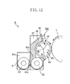
- FIG. 12 A method of measuring an amount of vibration will be described below with reference to FIG. 12 .
- acceleration of the regulating blade 46 by the vibration member 50 is measured by fixing an acceleration pick-up sensor 700 on the regulating blade 46 .
- FIG. 13 illustrates a measurement result of the acceleration according to the present exemplary embodiment.
- FIG. 13 illustrates a state in which the regulating blade 46 is intensely vibrated. Since a time span on the horizontal axis is long, the graph is squashed to be a form of a band.
- a measurement result of acceleration by the configuration according to the present exemplary embodiment is approximately 17 m/s 2 .
- the toner layer can be removed by vibrating the vibration member 50 of the regulating blade 46 when the developing sleeve 44 is slightly driven. It is understood as a result of examination by inventors of the present invention that the toner layer can be removed by the above operation when acceleration is 5 m/s 2 in the present exemplary embodiment.
- the non-image forming period includes a pre-multi-rotation period, i.e., a preparation operation performed when a power source of the image forming apparatus 100 is switched on, or a post-rotation period after image formation.
- a normal time period of a non-image forming region between sheets is 0.16 seconds for A4 size paper.
- the time is extended to 6.75 sec.
- the vibration member 50 in the developing device 4 of each color is vibrated 0.9 seconds.
- the noise due to vibration becomes large if the vibration members 50 of the developing devices 4 for all colors are vibrated at the same time. Consequently, the vibration member 50 is separately vibrated for each color during 6.75 seconds of time between sheets.
- power consumption while vibrating the vibration member 50 is large, a large power source will be required if the vibrating members 50 are vibrated at the same time, which leads to a rise in cost.
- the noise due to vibration is evaluated by an equivalent noise level (according to JIS Z8731), the following results are achieved.
- the noise is 55 dB in a normal image formation, 60 dB when the vibration member 50 in the developing device 4 for each color is separately vibrated, and 65 dB when the vibration members 50 for the four colors are simultaneously vibrated.
- 65 dB is equivalent to highway noise at daytime and is thus an unallowable level in an image forming apparatus. Therefore, in the present exemplary embodiment, the vibration member 50 in each of the developing device 4 is vibrated at a different time and not simultaneously vibrated in the vibration mode.
- the order of vibration with respect to color is important.
- the order is according to the above-described brightness of toner. Since a smear due to the aggregate is more noticeable for toner with lower brightness, the vibration member 50 of the developing device 4 containing toner with lower brightness is vibrated first. As a result, sufficient time can be acquired for the next image, so that the next image formation is performed after all of the aggregate is discharged.
- FIG. 14 illustrates a control block diagram for executing a vibration mode for vibrating the vibration member 50 .
- a control unit 400 is a controller that includes a CPU, a ROM, a RAM and the like, and controls image formation and drive of the vibration member 50 .
- the control unit 400 forms an image by driving the exposure device 3 and the developing device 4 based on the image signal received from an image signal generating unit 403 such as a document reading device.
- the control unit (controller) 400 controls a developing device driving unit 401 so that the developing sleeve 44 , the first developer convey agitating member 42 , and the second developer convey agitating member 43 of each developing device 4 are rotated during an operating mode.
- a full-color image forming apparatus uses the colors cyan, magenta, yellow, and black.
- these colors a smear due to an aggregate is barely visible in a toner image of yellow whose brightness is especially high. Therefore, it is important that the vibration member 50 of the developing device 4 containing a yellow developer whose brightness is highest is vibrated last. Image formation can be performed directly after the vibration member 50 of the yellow developer color is ended, so that a length of time between sheets, i.e., time during which image formation is stopped, can be minimized.
- the brightness of cyan and magenta are almost the same. Consequently, the order of vibrating the vibration members 50 corresponding to cyan and magenta developers is not so important, and it is necessary to first vibrate the vibration member 50 corresponding to a black developer whose brightness is lowest.
- a frequency of executing the vibration mode will be described below.
- the frequency of executing the vibration mode in the present exemplary embodiment can be changed according to an image ratio of an image to be formed.
- the image ratio according to the present exemplary embodiment is acquired by calculating a ratio of an area of a toner image to an entire area of a recording material on which the toner image is transferred.
- the image forming apparatus 100 includes a measurement unit which measures the image ratio.
- the above-described video count unit 301 illustrated in FIG. 2 can be a measurement unit.
- the video count unit 301 calculates the number of video counts by integrating image signals from the image processing apparatus 300 for each image.
- the video count unit 301 then calculates the amount of image with respect to each recording material on which an image is formed and acquires an image ratio of an output.
- FIG. 9 illustrates a relation between cohesion and frequency of aggregate generation.
- the frequency of aggregate generation was determined under a condition where an image ratio of an output is fixed at 8%, 6%, 4%, and 2%.
- a solid white image was formed on 300 sheets of A4 paper, and a halftone image formed on a first subsequent sheet was evaluated to determine whether a white streak is formed on the image.
- the measurement method of cohesion is described below.
- FIG. 10 illustrates a change in cohesion of toner according to a durable number of sheets.
- an original in which an image duty (i.e., image ratio) is 10% (for each color) is continuously formed on an A4 size paper in a normal temperature/normal humidity (23° C., 50% RH) environment.
- cohesion of toner increases according to the durable number of sheets.
- cohesion of toner is set to 40%.
- the frequency of the vibration mode in the present exemplary embodiment is set for a A4 size original as described in the table below.
- Image duty Vibration mode frequency 2% Every 200 sheets 4% Every 1000 sheets 6% or greater Every 5000 sheets
- vibration is applied at appropriate timing according to brightness of toner.
- the toner layer is removed from the back side of the regulating blade 46 before the toner layer grows.
- there is no image defect due to discharging the aggregate (foreign substance) there is no image forming apparatus that does not unnecessarily stop image formation can be provided.
- FIG. 11 illustrates a developing device according to the present exemplary embodiment.
- the flexible sheet member 49 is fixed on the regulating member 46 by a double-sided adhesive tape 49 a .
- a mylar sheet of 50 ⁇ m thick is used as the flexible sheet member 49 .
- the flexible sheet member 49 contacts the developing sleeve 44 across the developer. Therefore, the flexible sheet member 49 can crush the aggregate discharged by vibration.
- the flexible sheet member 49 is required to contact the developing sleeve 44 without blocking a developer coat on the developing sleeve 44 , the flexible sheet member 49 cannot crush all of the aggregate. Instead, the flexible sheet member 49 can only crush a small aggregate. Therefore, the effect of the flexible sheet member 49 is merely of a level subsidiary to the first exemplary embodiment. However, an image smearing caused by the aggregate is improved by the flexible sheet member 49 .
- a system using toner particles including a wax component will be described.
- the toner particles used in the present exemplary embodiment will be described below.
- the toner particles according to the present exemplary embodiment use pulverized toner including a wax component to attain oilless fixation. It is useful that a 1 to 20% by weight of wax is included in the toner particle. If the wax is less than 1% by weight, a separation failure may occur in the fixing device. Further, if the wax exceeds 20% by weight, a desired toner charging amount per unit weight (hereinafter referred to as Toribo) cannot be applied. Further, cohesion of the toner increases, so that a vibration frequency of the vibration member needs to be increased, causing lowering of productivity.
- Toribo desired toner charging amount per unit weight
- the present exemplary embodiment uses a pulverized toner including wax of 1 to 20% by weight as the toner particles to achieve oilless fixation.
- the toner particles are acquired by pulverizing and classifying after mixing and kneading binder resin, wax, colorant, and charge regulating agent.
- the method of producing the toner particles is not limited to the above-described method and can be produced by any of kneading, freezing, and pulverizing. Further, other additives can be included.
- Pulverized toner can be produced at comparatively low cost as compared to other toners such as polymerization toner.
- the toner component tends to exist near the toner surface layer due to the production method. Consequently, the wax tends to exude onto the developing sleeve 44 , and as a result, cohesion of the toner tends to become high.
- toner cohesion as described in the first exemplary embodiment is easily generated. Therefore, an amount of developer coat on the developing sleeve 44 becomes thin at a portion in which the aggregate has grown as compared to other portions, and density of an image becomes low.
- vibration is applied to move and loosen the toner layer.
- the toner layer is discharged outside the regulating blade 46 , so that the amount of developer coat is prevented from becoming small. It is more effective when the above-described toner is used.
- the image forming apparatus employs an intermediate transfer method using the intermediate transfer belt 51 as an intermediate transfer member.
- the image forming apparatus of the present invention is not limited to the above method.
- the image forming apparatus can use a direct transfer method.
- an electrostatic transfer belt as a recording material bearing member can carry and convey the recording material S, instead of the intermediate transfer belt 51 in the transfer device 5 according to the above-described exemplary embodiment. Consequently, the toner image is transferred to the recording material S.
- the present invention can be similarly applied to an image forming apparatus using the above-described direct transfer method to achieve a similar result.
Landscapes
- Physics & Mathematics (AREA)
- General Physics & Mathematics (AREA)
- Dry Development In Electrophotography (AREA)
- Control Or Security For Electrophotography (AREA)
Abstract
Description
| TABLE 1 | ||
| L* | ||
| K | 20.2 | ||
| M | 49.5 | ||
| C | 51.0 | ||
| Y | 88.0 | ||
L*(K)<<L*(M)≦L*(C)<<L*(Y)
The brightness of toner L* is measured by a method described below.
X=T/5×100
Y=C/5×100×0.6
Z=B/5×100×0.2,
cohesion (%) is calculated as
cohesion(%)=X+Y+Z.
| Image duty | |
||
| 2% | Every 200 |
||
| 4% | Every 1000 |
||
| 6% or greater | Every 5000 sheets | ||
Claims (10)
Applications Claiming Priority (2)
| Application Number | Priority Date | Filing Date | Title |
|---|---|---|---|
| JP2007-265680 | 2007-10-11 | ||
| JP2007265680A JP5100297B2 (en) | 2007-10-11 | 2007-10-11 | Image forming apparatus |
Publications (2)
| Publication Number | Publication Date |
|---|---|
| US20090097887A1 US20090097887A1 (en) | 2009-04-16 |
| US7729646B2 true US7729646B2 (en) | 2010-06-01 |
Family
ID=40534347
Family Applications (1)
| Application Number | Title | Priority Date | Filing Date |
|---|---|---|---|
| US12/249,706 Expired - Fee Related US7729646B2 (en) | 2007-10-11 | 2008-10-10 | Image forming apparatus |
Country Status (2)
| Country | Link |
|---|---|
| US (1) | US7729646B2 (en) |
| JP (1) | JP5100297B2 (en) |
Cited By (1)
| Publication number | Priority date | Publication date | Assignee | Title |
|---|---|---|---|---|
| US9122195B2 (en) | 2013-11-21 | 2015-09-01 | Canon Kabushiki Kaisha | Image forming apparatus |
Families Citing this family (5)
| Publication number | Priority date | Publication date | Assignee | Title |
|---|---|---|---|---|
| JP2008104108A (en) * | 2006-10-20 | 2008-05-01 | Fujitsu Ltd | Relay apparatus and fault monitoring method |
| JP5300567B2 (en) * | 2009-04-10 | 2013-09-25 | キヤノン株式会社 | Image forming apparatus |
| JP5633156B2 (en) * | 2010-02-24 | 2014-12-03 | 富士ゼロックス株式会社 | Developing device and image forming apparatus |
| JP5810061B2 (en) * | 2012-10-17 | 2015-11-11 | 京セラドキュメントソリューションズ株式会社 | Image forming apparatus |
| JP2019039955A (en) * | 2017-08-22 | 2019-03-14 | コニカミノルタ株式会社 | Developing device and image forming apparatus |
Citations (7)
| Publication number | Priority date | Publication date | Assignee | Title |
|---|---|---|---|---|
| US4398817A (en) * | 1981-03-25 | 1983-08-16 | Tokyo Shibaura Denki Kabushiki Kaisha | Magnetic developer apparatus for applying two different colored toners with the same applicator |
| JPS61103176A (en) | 1984-10-26 | 1986-05-21 | Kyocera Corp | Toner layer forming device |
| US4633808A (en) * | 1984-04-27 | 1987-01-06 | Mita Industrial Co., Ltd. | Developing process for electrophotography using a two-component developer |
| JPH0338669A (en) | 1989-07-05 | 1991-02-19 | Minolta Camera Co Ltd | Developing device |
| JPH11231645A (en) | 1998-02-12 | 1999-08-27 | Toshiba Corp | Developing device and image forming device |
| JP2001083757A (en) | 1999-09-10 | 2001-03-30 | Canon Inc | Image forming device |
| US20070110482A1 (en) | 2005-11-17 | 2007-05-17 | Yuichi Kazaki | Image forming apparatus |
Family Cites Families (2)
| Publication number | Priority date | Publication date | Assignee | Title |
|---|---|---|---|---|
| JP2005164728A (en) * | 2003-11-28 | 2005-06-23 | Kyocera Mita Corp | Image forming apparatus |
| JP4483669B2 (en) * | 2005-04-13 | 2010-06-16 | カシオ電子工業株式会社 | Toner for electrophotography |
-
2007
- 2007-10-11 JP JP2007265680A patent/JP5100297B2/en not_active Expired - Fee Related
-
2008
- 2008-10-10 US US12/249,706 patent/US7729646B2/en not_active Expired - Fee Related
Patent Citations (8)
| Publication number | Priority date | Publication date | Assignee | Title |
|---|---|---|---|---|
| US4398817A (en) * | 1981-03-25 | 1983-08-16 | Tokyo Shibaura Denki Kabushiki Kaisha | Magnetic developer apparatus for applying two different colored toners with the same applicator |
| US4633808A (en) * | 1984-04-27 | 1987-01-06 | Mita Industrial Co., Ltd. | Developing process for electrophotography using a two-component developer |
| JPS61103176A (en) | 1984-10-26 | 1986-05-21 | Kyocera Corp | Toner layer forming device |
| JPH0338669A (en) | 1989-07-05 | 1991-02-19 | Minolta Camera Co Ltd | Developing device |
| JPH11231645A (en) | 1998-02-12 | 1999-08-27 | Toshiba Corp | Developing device and image forming device |
| JP2001083757A (en) | 1999-09-10 | 2001-03-30 | Canon Inc | Image forming device |
| US20070110482A1 (en) | 2005-11-17 | 2007-05-17 | Yuichi Kazaki | Image forming apparatus |
| JP2007140062A (en) | 2005-11-17 | 2007-06-07 | Sharp Corp | Image forming apparatus |
Cited By (1)
| Publication number | Priority date | Publication date | Assignee | Title |
|---|---|---|---|---|
| US9122195B2 (en) | 2013-11-21 | 2015-09-01 | Canon Kabushiki Kaisha | Image forming apparatus |
Also Published As
| Publication number | Publication date |
|---|---|
| JP5100297B2 (en) | 2012-12-19 |
| US20090097887A1 (en) | 2009-04-16 |
| JP2009093073A (en) | 2009-04-30 |
Similar Documents
| Publication | Publication Date | Title |
|---|---|---|
| US8326180B2 (en) | Development device, process cartridge, and image forming apparatus | |
| JP4819547B2 (en) | Development device | |
| US7729646B2 (en) | Image forming apparatus | |
| US9020403B2 (en) | Developing device | |
| JP2007206458A (en) | Image forming apparatus | |
| JP2005283685A (en) | Image forming apparatus | |
| US20160004182A1 (en) | Image forming apparatus | |
| EP1505455A1 (en) | Developing apparatus | |
| JP2009063805A (en) | Electrostatic latent image developing carrier and developing method using the same | |
| JP2021071531A (en) | Image forming apparatus | |
| JP2005037878A (en) | Development apparatus, image forming apparatus, processing cartridge, and development method | |
| JP2003122118A (en) | Image forming device | |
| JP5300567B2 (en) | Image forming apparatus | |
| JP2011164205A (en) | Developing device and image forming apparatus | |
| JP5441330B2 (en) | Image forming apparatus | |
| US9122195B2 (en) | Image forming apparatus | |
| JPH1010784A (en) | Positive charge type one-component developer and image forming device using the same | |
| US7773922B2 (en) | Image forming apparatus | |
| JP5641838B2 (en) | Developing device and image forming apparatus | |
| US11841635B2 (en) | Developing device | |
| JP3386274B2 (en) | Image forming device | |
| JP2013097008A (en) | Method of specifying characteristic of developer, developer, and image forming apparatus | |
| JP7330858B2 (en) | image forming device | |
| JP2021071532A (en) | Image forming apparatus | |
| JP2021071533A (en) | Image forming apparatus |
Legal Events
| Date | Code | Title | Description |
|---|---|---|---|
| AS | Assignment |
Owner name: CANON KABUSHIKI KAISHA, JAPAN Free format text: ASSIGNMENT OF ASSIGNORS INTEREST;ASSIGNORS:FUJIWARA, MOTOHIRO;NOGUCHI, AKIHIRO;REEL/FRAME:021743/0190 Effective date: 20080925 Owner name: CANON KABUSHIKI KAISHA,JAPAN Free format text: ASSIGNMENT OF ASSIGNORS INTEREST;ASSIGNORS:FUJIWARA, MOTOHIRO;NOGUCHI, AKIHIRO;REEL/FRAME:021743/0190 Effective date: 20080925 |
|
| STCF | Information on status: patent grant |
Free format text: PATENTED CASE |
|
| FEPP | Fee payment procedure |
Free format text: PAYOR NUMBER ASSIGNED (ORIGINAL EVENT CODE: ASPN); ENTITY STATUS OF PATENT OWNER: LARGE ENTITY |
|
| FPAY | Fee payment |
Year of fee payment: 4 |
|
| MAFP | Maintenance fee payment |
Free format text: PAYMENT OF MAINTENANCE FEE, 8TH YEAR, LARGE ENTITY (ORIGINAL EVENT CODE: M1552) Year of fee payment: 8 |
|
| FEPP | Fee payment procedure |
Free format text: MAINTENANCE FEE REMINDER MAILED (ORIGINAL EVENT CODE: REM.); ENTITY STATUS OF PATENT OWNER: LARGE ENTITY |
|
| LAPS | Lapse for failure to pay maintenance fees |
Free format text: PATENT EXPIRED FOR FAILURE TO PAY MAINTENANCE FEES (ORIGINAL EVENT CODE: EXP.); ENTITY STATUS OF PATENT OWNER: LARGE ENTITY |
|
| STCH | Information on status: patent discontinuation |
Free format text: PATENT EXPIRED DUE TO NONPAYMENT OF MAINTENANCE FEES UNDER 37 CFR 1.362 |
|
| STCH | Information on status: patent discontinuation |
Free format text: PATENT EXPIRED DUE TO NONPAYMENT OF MAINTENANCE FEES UNDER 37 CFR 1.362 |
|
| FP | Lapsed due to failure to pay maintenance fee |
Effective date: 20220601 |