US7726344B2 - Device for dynamic control of a water flow - Google Patents
Device for dynamic control of a water flow Download PDFInfo
- Publication number
- US7726344B2 US7726344B2 US11/800,755 US80075507A US7726344B2 US 7726344 B2 US7726344 B2 US 7726344B2 US 80075507 A US80075507 A US 80075507A US 7726344 B2 US7726344 B2 US 7726344B2
- Authority
- US
- United States
- Prior art keywords
- flow
- piston
- chamber
- inlet
- dynamic control
- Prior art date
- Legal status (The legal status is an assumption and is not a legal conclusion. Google has not performed a legal analysis and makes no representation as to the accuracy of the status listed.)
- Expired - Fee Related, expires
Links
Images




Classifications
-
- G—PHYSICS
- G05—CONTROLLING; REGULATING
- G05D—SYSTEMS FOR CONTROLLING OR REGULATING NON-ELECTRIC VARIABLES
- G05D7/00—Control of flow
- G05D7/01—Control of flow without auxiliary power
- G05D7/0126—Control of flow without auxiliary power the sensing element being a piston or plunger associated with one or more springs
- G05D7/0133—Control of flow without auxiliary power the sensing element being a piston or plunger associated with one or more springs within the flow-path
-
- Y—GENERAL TAGGING OF NEW TECHNOLOGICAL DEVELOPMENTS; GENERAL TAGGING OF CROSS-SECTIONAL TECHNOLOGIES SPANNING OVER SEVERAL SECTIONS OF THE IPC; TECHNICAL SUBJECTS COVERED BY FORMER USPC CROSS-REFERENCE ART COLLECTIONS [XRACs] AND DIGESTS
- Y10—TECHNICAL SUBJECTS COVERED BY FORMER USPC
- Y10T—TECHNICAL SUBJECTS COVERED BY FORMER US CLASSIFICATION
- Y10T137/00—Fluid handling
- Y10T137/7722—Line condition change responsive valves
- Y10T137/7837—Direct response valves [i.e., check valve type]
- Y10T137/7847—With leak passage
-
- Y—GENERAL TAGGING OF NEW TECHNOLOGICAL DEVELOPMENTS; GENERAL TAGGING OF CROSS-SECTIONAL TECHNOLOGIES SPANNING OVER SEVERAL SECTIONS OF THE IPC; TECHNICAL SUBJECTS COVERED BY FORMER USPC CROSS-REFERENCE ART COLLECTIONS [XRACs] AND DIGESTS
- Y10—TECHNICAL SUBJECTS COVERED BY FORMER USPC
- Y10T—TECHNICAL SUBJECTS COVERED BY FORMER US CLASSIFICATION
- Y10T137/00—Fluid handling
- Y10T137/7722—Line condition change responsive valves
- Y10T137/7837—Direct response valves [i.e., check valve type]
- Y10T137/7904—Reciprocating valves
- Y10T137/7922—Spring biased
- Y10T137/7929—Spring coaxial with valve
-
- Y—GENERAL TAGGING OF NEW TECHNOLOGICAL DEVELOPMENTS; GENERAL TAGGING OF CROSS-SECTIONAL TECHNOLOGIES SPANNING OVER SEVERAL SECTIONS OF THE IPC; TECHNICAL SUBJECTS COVERED BY FORMER USPC CROSS-REFERENCE ART COLLECTIONS [XRACs] AND DIGESTS
- Y10—TECHNICAL SUBJECTS COVERED BY FORMER USPC
- Y10T—TECHNICAL SUBJECTS COVERED BY FORMER US CLASSIFICATION
- Y10T137/00—Fluid handling
- Y10T137/8593—Systems
- Y10T137/87265—Dividing into parallel flow paths with recombining
- Y10T137/87555—Having direct response valve [e.g., check valve, etc.]
Definitions
- the present disclosure relates to a device for dynamic control of a water flow as it is employed to stabilize the function of a thermostatic mixer.
- Thermostatic mixers which are suited to handling a large flow do not function properly if the flow that is demanded from them is much smaller than the maximum flow for which they are designed, which occurs, for example, when a thermostatic mixer intended for supplying a system with multiple shower units is used to supply a single shower unit. Under these circumstances, thermostatic mixers lose their stability and begin to oscillate so that the water flow piped from them is subjected to constant changes in the ratio of cold to warm water and thus sustains temperature fluctuations, which are unpleasant for the user and can even be harmful.
- This disadvantage can be eliminated by having the flow of cold water supplying the thermostatic mixer opposed by a resistance when small flows of mixed water are demanded, while suppressing or reducing this resistance when large flows of mixed water are demanded.
- the main task of the present invention is to produce a device for the dynamic control of a flow, the functioning of which in a broad range of applications must be independent of inlet pressure, so that during installation the device must not require any adjustments and must then not function improperly when considerable variations in inlet pressure appear.
- An additional task of the present invention is to produce a device of this type for the dynamic regulation of flow that is of simple construction and is economical, while ensuring a high degree of reliability and a long life.
- An additional task of the present invention is to produce a device of this type that can be fitted into a stopcock, with which thermostatic mixers are often equipped, so that no additional element must be incorporated into the system.
- a device for the dynamic control of a flow comprising, in a body, an inlet fitting, an inlet chamber, an outlet chamber, a piston, which is arranged between the inlet chamber and the outlet chamber and can be moved between a first position, which is displaced to the inlet chamber, wherein the piston constricts the flow between the inlet chamber and the outlet chamber when in the first position, and a second position, which is displaced to the outlet chamber, wherein the piston does not constrict the flow between the inlet chamber and the outlet chamber when in the second position, and a return spring, which acts upon the piston to move it to the first position, characterized by the fact that the inlet chamber is at least partly ring-shaped and encloses the piston, that the piston comprises a cylindrical shell section arranged in the area of the inlet chamber and a transverse segment, which defines an intermediate chamber and is crossed by an axially limited passage, that a flow-limiting means is arranged between the inlet fitting and the intermediate chamber, and that the
- the piston cannot be displaced by the inlet pressure, since this force is exerted radially and this process, whatever its value may be, does not tend to displace the piston out of its first position and into the direction of its second position.
- the pressure which builds in the intermediate chamber is determined through the drop in pressure sustained by the flow when passing from the inlet fitting to the intermediate chamber via the flow-limiting means.
- the effect exerted on the piston axially and in the opposite direction such as that of the return spring is based essentially on the difference between the pressure prevailing in the intermediate chamber and the pressure prevailing in the outlet chamber, which, due to the drop in pressure sustained by the flow when passing through the axially limited passage present in the transverse section of the piston is smaller than the former pressure.
- This pressure differential acts upon the transverse section of the piston and works to overcome the force of the return spring.
- Suitable dimensions for the cross section of the limited passage present in the transverse section of the piston, the strength of the return spring and the characteristics of the flow-limiting means make it possible for the piston not to shift out of its first position and into its second position, as long as a flow is discharged that is smaller than the maximum flow that can trigger instability in a thermostatic mixer.
- the displacement of the piston is regulated or controlled not by the absolute pressure prevailing in the chambers of the device, but rather by the pressure differential between the intermediate chamber and the outlet chamber, which depends on the flow and the resistances resisting it, but not on the absolute pressure, the function of the device is to a large extent independent of the inlet pressure, and the device in turn requires absolutely no adjustments during installation and exhibits no irregularities in function, even when the inlet pressure varies considerably.
- the flow-limiting means used in the inventive device is a widely available, low-cost valve of the prior art and is described for example in various forms in patent documents DE 40 41 116, DE 102 20 287, DE 102 28 490 and WO 01/04714.
- This valve provides the flow with a passage with reduced resistance as long as the flow volume of the flow does not exceed a limit preset through the construction of the flow-limiting means, while the valve, if the flow shows a tendency to exceed this limit, places a resistance against the flow, thereby limiting the flow to the maximum allowable value.
- Valves of this type are often fitted in devices, such as showers for example, in which the consumption must be limited—for legal reasons in certain cases. Because these valves are available for many different threshold values for flow, an adequate selection of the flow-limiting means and an appropriate proportioning of the parts of the device in the way described above are thus sufficient for creating an inventive flow-regulating device that can be adapted to the necessities of various specific applications.
- the intermediate chamber in the body of the device is advantageously limited through the inlet fitting, in which an intake chamber is defined and which features a transverse wall, in which axial circumferential passages are formed, which open into the ring-shaped inlet chamber, which encloses the piston, while the flow-limiting means is installed in the center of the transverse wall.
- the intake chamber and the axial circumferential passages can be formed from passages that are contained in a supplementary element, which is disposed between the body of the device and the inlet fitting, of which it is a part.
- This supplementary element can be advantageously manufactured from a synthetic material.
- the piston In its first closing position, the piston can abut an even surface of the inlet fitting, or it can partly engage a seat formed by the surface.
- thermostatic mixers are often provided with a stopcock for the purpose of simplifying maintenance, it is thus possible to install in series to the thermostatic mixer a single supplementary part that contains both the stopcock and the device for the dynamic regulation of flow instead of having to fit two different supplementary parts.
- a stopcock containing the inventive device is also a part of the invention.
- FIG. 1 represents an axial section of a device for dynamic control of a flow in accordance with a first embodiment of the present invention in a resting state or operating with reduced flow.
- FIG. 2 represents the same device shown in FIG. 1 in a state of operating with increased flow.
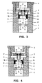
- FIGS. 3 and 4 represent a second embodiment of the inventive device analogous to FIGS. 1 and 2 .
- FIGS. 5 and 6 represent a third and fourth, respectively, embodiment of the invention in a resting state.
- FIGS. 7 and 8 represent a fifth embodiment of the invention in a resting state and a state of operating with increased flow, respectively.
- FIG. 9 represents how the device as illustrated in FIG. 6 can be fitted into a stopcock shown in a resting state.
- FIG. 10 represents the stopcock as illustrated in FIG. 9 in a state of operating with heavy flow.
- FIGS. 1 and 2 represent an axial section of a device for the dynamic control of a water flow of the type employed for the purpose of stabilizing the function of a thermostatic mixer, which comprises a body 1 , which in this case is completed on top by an inlet fitting 3 and forms an outlet fitting 4 .
- the inlet fitting 3 forms an intake chamber 5 in its interior
- the outlet fitting 4 forms an outflow passage 6 in its interior that is connected to an outlet chamber 7 that occupies the interior of the body 1 .
- a piston 8 Displaceably arranged in the outlet chamber 7 is a piston 8 , which features a cylindrical shell section 9 and a transverse section 11 crossed by an axially limited passage 12 .
- the shell section 9 and the transverse section 11 of the piston 8 define an intermediate chamber 16 .
- a ring-shaped inlet chamber 13 Formed in the body 1 and encircling the shell section 9 of the piston 8 is a ring-shaped inlet chamber 13 , which is defined by a transverse wall 19 of the inlet fitting 3 and is supplied by the intake chamber 5 via axial circumferential passages 2 , which is provided in the transverse wall 19 of the inlet fitting 3 .
- the outlet fitting 4 is defined by a transverse wall 14 crossed by a passage 15 .
- a spring 17 is arranged between this wall 14 and the piston 8 , which in turn presses the piston 8 with the edge of its shell section 9 against the transverse wall 19 of the inlet fitting 3 , which defines the inlet chamber 13 . This is the resting position of the device illustrated in FIG. 1 .
- a flow-limiting means 10 Installed in the central area of the transverse wall 19 of the inlet fitting 3 is a flow-limiting means 10 , which in turn is located between the intake chamber 5 and the intermediate chamber 16 . This permanently prevents the passage of a flow, which however cannot exceed a threshold value that is determined through the characteristics of the flow-limiting means, from the intake chamber 5 to the intermediate chamber 16 and then from there to the outlet chamber 7 and to the outflow passage 6 . Because a thermostatic mixer serves to stabilize, a flow-limiting means 10 is selected so that the flow limit it defines corresponds to the maximum value of the flow that is able to cause the oscillation of the thermostatic mixer concerned.
- the entire device can be penetrated by a flow, which is limited by the flow-limiting means 10 .
- the inlet pressure is present in the intake chamber 5 and in the inlet chamber 13
- the pressure in the intermediate chamber 16 is negligibly smaller than the inlet pressure due to the drop in pressure sustained by the flow as a result of crossing through the flow-limiting means 10
- the pressure in the outlet chamber 7 is further reduced due to the drop in pressure sustained by the flow as a result of crossing through the limited passage 12 .
- the piston is acted upon to the effect that it moves away from the inlet fitting 3 , while the spring 17 works against this process.
- the piston is practically not influenced by the inlet pressure present in the inlet chamber, since this pressure acts radially.
- the drops in pressure sustained by the flow depend only on the intensity of the flow and the resistances placed against it and not on the absolute value of the pressure. The behavior of the piston in turn is not influenced by the inlet pressure value and changes therein.
- the limited axial passage 12 and the return spring 17 must be proportioned relative to one another so that the effect of the spring 17 is essentially equal to the force acting to displace the piston out of the first position and into the second position, when the maximum flow allowed by the flow-limiting means 10 is discharged.
- the piston in turn holds its first position illustrated in FIG. 1 as long as the demanded flow remains below the nominal maximum value.
- FIG. 3 through 8 which show other embodiments of the invention, the parts that are identical to or correspond to the parts of the first embodiment are labeled with the same reference numbers.
- FIG. 5 illustrates an embodiment that distinguishes itself from the previous embodiments in terms of construction by featuring male instead of female connection parts.
- This embodiment also distinguishes itself from the previous in the construction of the inlet fitting 3 , which in this example features a supplementary element 19 that is disposed between the fitting 3 and the body 1 of the device and becomes the part of the inlet fitting 3 .
- the supplementary element 19 defines the intake chamber 5 and forms the axial circumferential passages 2 , which open into the inlet chamber 13 .
- the use of the supplementary element 19 allows the construction of the inlet fitting 3 to be simplified and is especially economical if the supplementary element 19 is made of a synthetic material.
- FIG. 6 shows a further configuration of the embodiment illustrated in FIG. 5 .
- the edge of the end of the shell section 9 of the piston 8 which in the previous embodiments abuts the level surface of the inlet fitting 3 , partly engages in a seat recessed in this level surface.
- the advantage of this arrangement is found in the fact that if an abrupt variation of the outlet flow occurs, the piston 8 can coincidentally sustain a limited displacement that can bring it to the second opening position, even when the outlet flow has not exceeded the predetermined value for the suppression of the constriction of the passage cross section of the cold inlet water. In this case, if the piston 8 is closed by simply abutting the edge of the shell section 9 , the passage cross-section automatically opens at least temporarily.
- FIGS. 7 and 8 also show that a smaller gap 28 is provided between the piston 8 and the body 1 of the device.
- this gap facilitates the passage of a reduced flow in addition to the flow allowed by the flow-limiting means 10 without requiring a modification of the function of the device, which is projected taking into consideration this flow as well.
- the presence of this gap makes it possible to manufacture parts with greater tolerances and thereby at reduced cost.
- FIGS. 9 and 10 illustrate, in a resting state and in a state with a large flow, respectively, a stopcock containing a device for dynamically controlling the flow as shown in FIG. 6 .
- a half of the body 20 [MD 2 ], which is illustrated in the figures above, is essentially equivalent in terms of form and parts contained to the upper portion of the device illustrated in FIG. 6 , while the bottom portion of the body 20 contains a normal closure element 21 of a stopcock, the seal 22 of which acts against the transverse wall 14 intersected by the passage 15 .
- a side of the body 20 features the outlet fitting 4 with the outflow passage 6 . This results in a compact component with dimensions that are only slightly greater than those of a normal stopcock and that facilitates a simplification of the system by having only one component, rather than two, installed in series with a thermostatic mixer.
- the supplementary element 19 which is a part of the inlet fitting 3 , is elongated, resulting in a cylinder 23 being formed in which the piston 8 runs.
- the inlet chamber 13 is formed by openings formed in this cylinder 23 .
- the invention facilitates the realization of a device for the dynamic control of a water flow that is practically immune to variations in the inlet pressure of cold water, the flow of which it regulates for the purpose of sending it to a thermostatic mixer to stabilize the mode of functioning thereof.
- a device for the dynamic control of a water flow that is practically immune to variations in the inlet pressure of cold water, the flow of which it regulates for the purpose of sending it to a thermostatic mixer to stabilize the mode of functioning thereof.
Landscapes
- General Physics & Mathematics (AREA)
- Engineering & Computer Science (AREA)
- Automation & Control Theory (AREA)
- Physics & Mathematics (AREA)
- Safety Valves (AREA)
- Multiple-Way Valves (AREA)
- Cyclones (AREA)
- Magnetically Actuated Valves (AREA)
- Devices That Are Associated With Refrigeration Equipment (AREA)
- Control Of Non-Electrical Variables (AREA)
- Domestic Plumbing Installations (AREA)
- Lift Valve (AREA)
- Details Of Valves (AREA)
- Flow Control (AREA)
Applications Claiming Priority (4)
| Application Number | Priority Date | Filing Date | Title |
|---|---|---|---|
| ITTO2004A0776 | 2004-11-09 | ||
| ITTO20040776 ITTO20040776A1 (it) | 2004-11-09 | 2004-11-09 | Dispositivo per il controllo dinamico di un flusso di acqua |
| ITTO2004A000776 | 2004-11-09 | ||
| PCT/IB2005/003360 WO2006051391A1 (de) | 2004-11-09 | 2005-11-09 | Vorrichtung zur dynamischen regelung eines wasserflusses |
Related Parent Applications (1)
| Application Number | Title | Priority Date | Filing Date |
|---|---|---|---|
| PCT/IB2005/003360 Continuation WO2006051391A1 (de) | 2004-11-09 | 2005-11-09 | Vorrichtung zur dynamischen regelung eines wasserflusses |
Publications (2)
| Publication Number | Publication Date |
|---|---|
| US20070289643A1 US20070289643A1 (en) | 2007-12-20 |
| US7726344B2 true US7726344B2 (en) | 2010-06-01 |
Family
ID=35770292
Family Applications (1)
| Application Number | Title | Priority Date | Filing Date |
|---|---|---|---|
| US11/800,755 Expired - Fee Related US7726344B2 (en) | 2004-11-09 | 2007-05-07 | Device for dynamic control of a water flow |
Country Status (9)
| Country | Link |
|---|---|
| US (1) | US7726344B2 (de) |
| EP (1) | EP1810101B1 (de) |
| JP (1) | JP2008519378A (de) |
| CN (1) | CN101088057B (de) |
| AT (1) | ATE429670T1 (de) |
| CA (1) | CA2587156C (de) |
| DE (1) | DE502005007160D1 (de) |
| IT (1) | ITTO20040776A1 (de) |
| WO (1) | WO2006051391A1 (de) |
Cited By (4)
| Publication number | Priority date | Publication date | Assignee | Title |
|---|---|---|---|---|
| WO2011148244A2 (es) | 2010-05-24 | 2011-12-01 | Riano Gutierrez Ismael Hernan | Válvula reguladora automática de flujo |
| US11420515B2 (en) * | 2017-06-29 | 2022-08-23 | Plastic Omnium Advanced Innovation And Research | Ventilation flow rate regulator for a pressurized vehicle tank |
| US12038097B2 (en) | 2020-08-04 | 2024-07-16 | Fike Corporation | Slide valve |
| US20250389338A1 (en) * | 2022-07-13 | 2025-12-25 | Enapter S.r.l. | Orifice check valve |
Families Citing this family (5)
| Publication number | Priority date | Publication date | Assignee | Title |
|---|---|---|---|---|
| US8850827B2 (en) * | 2010-03-05 | 2014-10-07 | Honeywell International Inc. | Control valve with radial seals |
| CN101922579B (zh) * | 2010-05-28 | 2011-11-30 | 钟国强 | 一种自动限流节水嘴 |
| US20150277463A1 (en) * | 2014-03-25 | 2015-10-01 | Honeywell International Inc. | System for communication, optimization and demand control for an appliance |
| CN111033216A (zh) * | 2017-08-24 | 2020-04-17 | 霍尼韦尔国际公司 | 用于颗粒传感器的气流控制 |
| CN118242448A (zh) * | 2023-12-05 | 2024-06-25 | 箭牌家居集团股份有限公司 | 排水装置及出水设备 |
Citations (11)
| Publication number | Priority date | Publication date | Assignee | Title |
|---|---|---|---|---|
| GB721031A (en) | 1953-07-16 | 1954-12-29 | Cosby Donald Philipps Smallpei | Fluid flow regulator |
| US3809111A (en) | 1970-07-10 | 1974-05-07 | A Olsson | Pressure reduction valve |
| US3814134A (en) * | 1971-10-21 | 1974-06-04 | Fiat Spa | Servo-operated electrovalve |
| US4044791A (en) * | 1975-12-10 | 1977-08-30 | City Tank Corporation | Valve assembly |
| US4428396A (en) * | 1978-07-19 | 1984-01-31 | City Tank Corporation | Adjustable valve assembly |
| DE4030159A1 (de) | 1990-09-24 | 1992-03-26 | Teves Gmbh Alfred | Stromregelventil |
| US5099875A (en) | 1991-02-06 | 1992-03-31 | Moog Controls, Inc. | Fluid flow regulator |
| US6129112A (en) | 1998-02-17 | 2000-10-10 | Huthmann; Otto | Flow regulator |
| US20040007269A1 (en) | 2002-07-12 | 2004-01-15 | Larsen Todd W. | Inline pressure reducing regulator |
| US7370667B2 (en) * | 2004-06-01 | 2008-05-13 | Nelson Irrigation Corporation | Flow through pressure regulator with pinch valve |
| US7575021B2 (en) * | 2004-12-23 | 2009-08-18 | Black Market Sportz Limited | Gas pressure regulator |
Family Cites Families (9)
| Publication number | Priority date | Publication date | Assignee | Title |
|---|---|---|---|---|
| JPS5093627U (de) * | 1973-12-27 | 1975-08-06 | ||
| FR2573716B1 (fr) * | 1984-11-23 | 1987-02-27 | Sncf | Dispositif de reperage automatique des poteaux catenaires de voie ferree pour contribuer au reperage des defauts detectes sur la voie ferree. |
| JPH0314605Y2 (de) * | 1985-12-30 | 1991-04-02 | ||
| DE4041116A1 (de) | 1990-12-21 | 1992-06-25 | Wildfang Dieter Gmbh | Durchflussregler |
| JPH10288266A (ja) * | 1997-04-15 | 1998-10-27 | Tlv Co Ltd | ばね付勢逆止弁 |
| CN2357189Y (zh) * | 1999-02-11 | 2000-01-05 | 廊坊中油管道汇力实业有限公司 | 动态恒流阀 |
| DE19932596C2 (de) | 1999-07-13 | 2002-10-17 | Wildfang Dieter Gmbh | Durchflußmengenregler |
| DE10220287B4 (de) | 2002-05-07 | 2004-09-16 | Dieter Wildfang Gmbh | Durchflußmengenregler |
| DE10228490C1 (de) | 2002-06-26 | 2003-11-06 | Wildfang Dieter Gmbh | Durchflussmengenregler |
-
2004
- 2004-11-09 IT ITTO20040776 patent/ITTO20040776A1/it unknown
-
2005
- 2005-11-09 CA CA 2587156 patent/CA2587156C/en not_active Expired - Fee Related
- 2005-11-09 WO PCT/IB2005/003360 patent/WO2006051391A1/de not_active Ceased
- 2005-11-09 JP JP2007540740A patent/JP2008519378A/ja active Pending
- 2005-11-09 DE DE200550007160 patent/DE502005007160D1/de not_active Expired - Lifetime
- 2005-11-09 EP EP05800682A patent/EP1810101B1/de not_active Expired - Lifetime
- 2005-11-09 AT AT05800682T patent/ATE429670T1/de not_active IP Right Cessation
- 2005-11-09 CN CN2005800383690A patent/CN101088057B/zh not_active Expired - Fee Related
-
2007
- 2007-05-07 US US11/800,755 patent/US7726344B2/en not_active Expired - Fee Related
Patent Citations (11)
| Publication number | Priority date | Publication date | Assignee | Title |
|---|---|---|---|---|
| GB721031A (en) | 1953-07-16 | 1954-12-29 | Cosby Donald Philipps Smallpei | Fluid flow regulator |
| US3809111A (en) | 1970-07-10 | 1974-05-07 | A Olsson | Pressure reduction valve |
| US3814134A (en) * | 1971-10-21 | 1974-06-04 | Fiat Spa | Servo-operated electrovalve |
| US4044791A (en) * | 1975-12-10 | 1977-08-30 | City Tank Corporation | Valve assembly |
| US4428396A (en) * | 1978-07-19 | 1984-01-31 | City Tank Corporation | Adjustable valve assembly |
| DE4030159A1 (de) | 1990-09-24 | 1992-03-26 | Teves Gmbh Alfred | Stromregelventil |
| US5099875A (en) | 1991-02-06 | 1992-03-31 | Moog Controls, Inc. | Fluid flow regulator |
| US6129112A (en) | 1998-02-17 | 2000-10-10 | Huthmann; Otto | Flow regulator |
| US20040007269A1 (en) | 2002-07-12 | 2004-01-15 | Larsen Todd W. | Inline pressure reducing regulator |
| US7370667B2 (en) * | 2004-06-01 | 2008-05-13 | Nelson Irrigation Corporation | Flow through pressure regulator with pinch valve |
| US7575021B2 (en) * | 2004-12-23 | 2009-08-18 | Black Market Sportz Limited | Gas pressure regulator |
Cited By (5)
| Publication number | Priority date | Publication date | Assignee | Title |
|---|---|---|---|---|
| WO2011148244A2 (es) | 2010-05-24 | 2011-12-01 | Riano Gutierrez Ismael Hernan | Válvula reguladora automática de flujo |
| US8485220B2 (en) | 2010-05-24 | 2013-07-16 | Ismael Hernan RIAÑO GUTIERREZ | Automatic flow regulator valve |
| US11420515B2 (en) * | 2017-06-29 | 2022-08-23 | Plastic Omnium Advanced Innovation And Research | Ventilation flow rate regulator for a pressurized vehicle tank |
| US12038097B2 (en) | 2020-08-04 | 2024-07-16 | Fike Corporation | Slide valve |
| US20250389338A1 (en) * | 2022-07-13 | 2025-12-25 | Enapter S.r.l. | Orifice check valve |
Also Published As
| Publication number | Publication date |
|---|---|
| ITTO20040776A1 (it) | 2005-02-09 |
| ATE429670T1 (de) | 2009-05-15 |
| CN101088057A (zh) | 2007-12-12 |
| CA2587156C (en) | 2011-02-08 |
| CN101088057B (zh) | 2010-12-08 |
| EP1810101B1 (de) | 2009-04-22 |
| US20070289643A1 (en) | 2007-12-20 |
| WO2006051391A1 (de) | 2006-05-18 |
| EP1810101A1 (de) | 2007-07-25 |
| DE502005007160D1 (de) | 2009-06-04 |
| CA2587156A1 (en) | 2006-05-18 |
| JP2008519378A (ja) | 2008-06-05 |
Similar Documents
| Publication | Publication Date | Title |
|---|---|---|
| US20070289643A1 (en) | Device for dynamic control of a water flow | |
| US5931374A (en) | Flow control ports for a thermostatic mixing faucet | |
| US7740183B2 (en) | Thermostatic mixer with device for dynamic regulation of a water flow | |
| US5647531A (en) | Thermostatic control valve system for use in emergency shower and eyewash systems | |
| US20070289642A1 (en) | Device for dynamic control of a water flow | |
| JP4602335B2 (ja) | 圧力供給弁 | |
| US7163157B2 (en) | Automatic compensating valve for individual shower and tub/shower combination fixtures | |
| US4577653A (en) | Anti-siphon and anti-knock diverter valve | |
| EP2256391A2 (de) | Drucksteuerungs-Ventilanordnung | |
| EP0880734B1 (de) | Durchflussmengesteuerungsöffnungen für eine thermostatische mischbatterie | |
| US5174332A (en) | Constant flow valve | |
| US7344088B2 (en) | Dual-function valve with pressure adjustment and temperature control functions | |
| EP0740808B1 (de) | Thermostatgeregeltes mischventil | |
| US6129112A (en) | Flow regulator | |
| USRE32981E (en) | Anti-siphon and anti-knock diverter valve | |
| US5372157A (en) | Automatic bypass valve | |
| US7681597B2 (en) | Thermostatic mixer with device for dynamic regulation of a water flow | |
| KR101956546B1 (ko) | 가변식 정유량밸브 | |
| CN101652735B (zh) | 压力阀 | |
| US5397053A (en) | Temperature responsive, pilot operated line valve with shape memory alloy actuator | |
| WO1997032147A1 (en) | Mixing valve responsive to inlet pressure conditions | |
| EP3708885B1 (de) | Verbesserte ausgabekartusche zur abgabe von wasser in einem wassersystem | |
| US4509677A (en) | Mixing valve | |
| AU3338600A (en) | Pressure reducing valve | |
| JPH0449694Y2 (de) |
Legal Events
| Date | Code | Title | Description |
|---|---|---|---|
| AS | Assignment |
Owner name: MASCO CORPORATION OF INDIANA, INDIANA Free format text: ASSIGNMENT OF ASSIGNORS INTEREST;ASSIGNOR:KNAPP, ALFONS;REEL/FRAME:019335/0646 Effective date: 20070124 Owner name: MASCO CORPORATION OF INDIANA,INDIANA Free format text: ASSIGNMENT OF ASSIGNORS INTEREST;ASSIGNOR:KNAPP, ALFONS;REEL/FRAME:019335/0646 Effective date: 20070124 |
|
| REMI | Maintenance fee reminder mailed | ||
| LAPS | Lapse for failure to pay maintenance fees | ||
| STCH | Information on status: patent discontinuation |
Free format text: PATENT EXPIRED DUE TO NONPAYMENT OF MAINTENANCE FEES UNDER 37 CFR 1.362 |
|
| STCH | Information on status: patent discontinuation |
Free format text: PATENT EXPIRED DUE TO NONPAYMENT OF MAINTENANCE FEES UNDER 37 CFR 1.362 |
|
| FP | Lapsed due to failure to pay maintenance fee |
Effective date: 20140601 |