US7722984B2 - Reinforced pouch type secondary battery - Google Patents
Reinforced pouch type secondary battery Download PDFInfo
- Publication number
- US7722984B2 US7722984B2 US10/462,729 US46272903A US7722984B2 US 7722984 B2 US7722984 B2 US 7722984B2 US 46272903 A US46272903 A US 46272903A US 7722984 B2 US7722984 B2 US 7722984B2
- Authority
- US
- United States
- Prior art keywords
- reinforcement member
- pouch
- electrode assembly
- secondary battery
- positive
- Prior art date
- Legal status (The legal status is an assumption and is not a legal conclusion. Google has not performed a legal analysis and makes no representation as to the accuracy of the status listed.)
- Expired - Lifetime, expires
Links
- 230000002787 reinforcement Effects 0.000 claims abstract description 86
- 239000011888 foil Substances 0.000 claims description 33
- 229910052751 metal Inorganic materials 0.000 claims description 27
- 239000002184 metal Substances 0.000 claims description 27
- 239000000463 material Substances 0.000 claims description 23
- 229920005989 resin Polymers 0.000 claims description 14
- 239000011347 resin Substances 0.000 claims description 14
- 239000004840 adhesive resin Substances 0.000 claims description 9
- 229920006223 adhesive resin Polymers 0.000 claims description 9
- 239000000835 fiber Substances 0.000 claims description 7
- 239000002131 composite material Substances 0.000 claims description 6
- 230000037431 insertion Effects 0.000 claims description 4
- 238000003780 insertion Methods 0.000 claims description 4
- 239000007769 metal material Substances 0.000 claims description 3
- 239000010408 film Substances 0.000 description 7
- 230000008961 swelling Effects 0.000 description 7
- 229910052782 aluminium Inorganic materials 0.000 description 6
- XAGFODPZIPBFFR-UHFFFAOYSA-N aluminium Chemical compound [Al] XAGFODPZIPBFFR-UHFFFAOYSA-N 0.000 description 6
- 239000005025 cast polypropylene Substances 0.000 description 6
- -1 polypropylene Polymers 0.000 description 6
- 239000008151 electrolyte solution Substances 0.000 description 5
- 230000006835 compression Effects 0.000 description 4
- 238000007906 compression Methods 0.000 description 4
- 229920000139 polyethylene terephthalate Polymers 0.000 description 4
- 239000005020 polyethylene terephthalate Substances 0.000 description 4
- WHXSMMKQMYFTQS-UHFFFAOYSA-N Lithium Chemical compound [Li] WHXSMMKQMYFTQS-UHFFFAOYSA-N 0.000 description 3
- 239000004677 Nylon Substances 0.000 description 3
- 239000004743 Polypropylene Substances 0.000 description 3
- 239000011248 coating agent Substances 0.000 description 3
- 238000000576 coating method Methods 0.000 description 3
- 238000002347 injection Methods 0.000 description 3
- 239000007924 injection Substances 0.000 description 3
- 229910052744 lithium Inorganic materials 0.000 description 3
- 229920001778 nylon Polymers 0.000 description 3
- 229920001155 polypropylene Polymers 0.000 description 3
- 230000001681 protective effect Effects 0.000 description 3
- RYGMFSIKBFXOCR-UHFFFAOYSA-N Copper Chemical compound [Cu] RYGMFSIKBFXOCR-UHFFFAOYSA-N 0.000 description 2
- XEEYBQQBJWHFJM-UHFFFAOYSA-N Iron Chemical compound [Fe] XEEYBQQBJWHFJM-UHFFFAOYSA-N 0.000 description 2
- 239000003575 carbonaceous material Substances 0.000 description 2
- 239000011889 copper foil Substances 0.000 description 2
- 239000012212 insulator Substances 0.000 description 2
- 238000003475 lamination Methods 0.000 description 2
- FUJCRWPEOMXPAD-UHFFFAOYSA-N lithium oxide Chemical compound [Li+].[Li+].[O-2] FUJCRWPEOMXPAD-UHFFFAOYSA-N 0.000 description 2
- 229910001947 lithium oxide Inorganic materials 0.000 description 2
- 238000002844 melting Methods 0.000 description 2
- 230000008018 melting Effects 0.000 description 2
- 239000007773 negative electrode material Substances 0.000 description 2
- 229920000642 polymer Polymers 0.000 description 2
- 239000002952 polymeric resin Substances 0.000 description 2
- 239000007774 positive electrode material Substances 0.000 description 2
- 239000002002 slurry Substances 0.000 description 2
- 229920003002 synthetic resin Polymers 0.000 description 2
- 239000010409 thin film Substances 0.000 description 2
- 238000003466 welding Methods 0.000 description 2
- HBBGRARXTFLTSG-UHFFFAOYSA-N Lithium ion Chemical compound [Li+] HBBGRARXTFLTSG-UHFFFAOYSA-N 0.000 description 1
- 239000004952 Polyamide Substances 0.000 description 1
- 239000000853 adhesive Substances 0.000 description 1
- 230000001070 adhesive effect Effects 0.000 description 1
- 230000000712 assembly Effects 0.000 description 1
- 238000000429 assembly Methods 0.000 description 1
- 238000007599 discharging Methods 0.000 description 1
- 230000001771 impaired effect Effects 0.000 description 1
- 229910052742 iron Inorganic materials 0.000 description 1
- 238000010030 laminating Methods 0.000 description 1
- 229910001416 lithium ion Inorganic materials 0.000 description 1
- 239000000155 melt Substances 0.000 description 1
- 229910052987 metal hydride Inorganic materials 0.000 description 1
- 238000004806 packaging method and process Methods 0.000 description 1
- 229920002647 polyamide Polymers 0.000 description 1
- 230000003014 reinforcing effect Effects 0.000 description 1
- 230000000717 retained effect Effects 0.000 description 1
- 238000007789 sealing Methods 0.000 description 1
- 229910001220 stainless steel Inorganic materials 0.000 description 1
- 239000010935 stainless steel Substances 0.000 description 1
Images
Classifications
-
- H—ELECTRICITY
- H01—ELECTRIC ELEMENTS
- H01M—PROCESSES OR MEANS, e.g. BATTERIES, FOR THE DIRECT CONVERSION OF CHEMICAL ENERGY INTO ELECTRICAL ENERGY
- H01M50/00—Constructional details or processes of manufacture of the non-active parts of electrochemical cells other than fuel cells, e.g. hybrid cells
- H01M50/50—Current conducting connections for cells or batteries
- H01M50/572—Means for preventing undesired use or discharge
- H01M50/574—Devices or arrangements for the interruption of current
- H01M50/579—Devices or arrangements for the interruption of current in response to shock
-
- H—ELECTRICITY
- H01—ELECTRIC ELEMENTS
- H01M—PROCESSES OR MEANS, e.g. BATTERIES, FOR THE DIRECT CONVERSION OF CHEMICAL ENERGY INTO ELECTRICAL ENERGY
- H01M50/00—Constructional details or processes of manufacture of the non-active parts of electrochemical cells other than fuel cells, e.g. hybrid cells
- H01M50/10—Primary casings; Jackets or wrappings
- H01M50/172—Arrangements of electric connectors penetrating the casing
- H01M50/174—Arrangements of electric connectors penetrating the casing adapted for the shape of the cells
- H01M50/178—Arrangements of electric connectors penetrating the casing adapted for the shape of the cells for pouch or flexible bag cells
-
- H—ELECTRICITY
- H01—ELECTRIC ELEMENTS
- H01M—PROCESSES OR MEANS, e.g. BATTERIES, FOR THE DIRECT CONVERSION OF CHEMICAL ENERGY INTO ELECTRICAL ENERGY
- H01M50/00—Constructional details or processes of manufacture of the non-active parts of electrochemical cells other than fuel cells, e.g. hybrid cells
- H01M50/10—Primary casings; Jackets or wrappings
- H01M50/183—Sealing members
- H01M50/186—Sealing members characterised by the disposition of the sealing members
-
- H—ELECTRICITY
- H01—ELECTRIC ELEMENTS
- H01M—PROCESSES OR MEANS, e.g. BATTERIES, FOR THE DIRECT CONVERSION OF CHEMICAL ENERGY INTO ELECTRICAL ENERGY
- H01M50/00—Constructional details or processes of manufacture of the non-active parts of electrochemical cells other than fuel cells, e.g. hybrid cells
- H01M50/50—Current conducting connections for cells or batteries
- H01M50/543—Terminals
- H01M50/547—Terminals characterised by the disposition of the terminals on the cells
- H01M50/55—Terminals characterised by the disposition of the terminals on the cells on the same side of the cell
-
- H—ELECTRICITY
- H01—ELECTRIC ELEMENTS
- H01M—PROCESSES OR MEANS, e.g. BATTERIES, FOR THE DIRECT CONVERSION OF CHEMICAL ENERGY INTO ELECTRICAL ENERGY
- H01M50/00—Constructional details or processes of manufacture of the non-active parts of electrochemical cells other than fuel cells, e.g. hybrid cells
- H01M50/10—Primary casings; Jackets or wrappings
- H01M50/102—Primary casings; Jackets or wrappings characterised by their shape or physical structure
- H01M50/103—Primary casings; Jackets or wrappings characterised by their shape or physical structure prismatic or rectangular
-
- Y—GENERAL TAGGING OF NEW TECHNOLOGICAL DEVELOPMENTS; GENERAL TAGGING OF CROSS-SECTIONAL TECHNOLOGIES SPANNING OVER SEVERAL SECTIONS OF THE IPC; TECHNICAL SUBJECTS COVERED BY FORMER USPC CROSS-REFERENCE ART COLLECTIONS [XRACs] AND DIGESTS
- Y02—TECHNOLOGIES OR APPLICATIONS FOR MITIGATION OR ADAPTATION AGAINST CLIMATE CHANGE
- Y02E—REDUCTION OF GREENHOUSE GAS [GHG] EMISSIONS, RELATED TO ENERGY GENERATION, TRANSMISSION OR DISTRIBUTION
- Y02E60/00—Enabling technologies; Technologies with a potential or indirect contribution to GHG emissions mitigation
- Y02E60/10—Energy storage using batteries
Definitions
- the present invention relates to a secondary battery, and more particularly, a secondary battery in a pouch casing with a reinforcement structure.
- Secondary batteries are rechargeable and can be made in small sizes with high capacities.
- Typical examples of secondary batteries include nickel-metal hydride (Ni-MH) batteries and lithium (Li) secondary batteries.
- Secondary batteries are classified into cylindrical batteries using a cylindrical aluminum can, rectangular batteries using a rectangular aluminum can, and pouch type batteries where the battery is accommodated in a thin-film pouch type casing.
- a pouch type secondary battery as shown in FIG. 1 , includes an electrode assembly 10 which generates a predetermined current, and a pouch casing 20 which encloses and hermatically seals the electrode assembly 10 .
- the electrode assembly 10 has an electrode tab 14 drawn from one side which is connected with a lead 15 that serves as an electrical path leading outside.
- the lead 15 has a protective tape 16 adhered to its surface so that it extends outside the pouch casing 20 .
- the pouch casing 20 includes a case body 22 having an internal space in which the electrode assembly 10 is retained, and a cover 24 integrally extending from one end of the case body 22 .
- a flange 23 is formed at the periphery of the case body 22 and is configured to be welded with the cover 24 to hermetically seal the case body 22 .
- the pouch casing 20 of the pouch type secondary battery having the above-described configuration is typically made of a metal foil and resin materials.
- FIG. 2 is a cross-sectional view taken along the line I-I shown in FIG. 1 .
- the pouch casing 20 is formed of composite materials compressed such that a thermal adhesion layer 22 b is formed on the inner face of a foil 22 a .
- the thermal adhesion layer 22 b may be formed from denatured polypropylene, e.g., cast polypropylene (CPP).
- the foil 22 a may be made of a metal, e.g., Al.
- the pouch casing 20 can be sealed by heat compression in a state in which thermal adhesion layers of the case body 22 and the pouch cover 24 are joined to each other.
- the pouch casing having the above-described configuration is very thin, there is a limitation in protecting the electrode assembly housed in the pouch casing.
- the thickness of a metal foil provided for the purpose of maintaining the strength of the casing is only several tens of micrometers. Accordingly, the metal foil is very weak against external impacts.
- the melting point of the thermal adhesion layer made of, for example, CPP is about 130° C. to 140° C.
- the melting point of a separator of the electrode assembly housed in the pouch casing is also about 130° C. to 140° C.
- the temperature of thermally welding a case body and a pouch cover of the pouch casing is about 180° C. to 210° C.
- the thermal adhesion layer and the separator may melt, or the separator may be fusibly fixed with the thermal adhesion layer.
- the thermal adhesion layer melts exposing the Al metal film inside, so that the Al metal film may be short-circuited from the electrode assembly.
- a stacked electrode assembly is housed in the pouch casing and has a bi-cell structure, as shown in FIG. 3 .
- the bi-cell structure is a unit of an electrode assembly, and is generally constructed such that a positive electrode sheet 11 is stacked on both faces of a negative electrode sheet 12 with a separator 13 interposed between each of the positive and negative electrode sheets 11 and 12 .
- the area of each separator 13 defining the positive and negative electrode sheets 11 and 12 is greatest and the area of the positive electrode sheet 11 is smallest.
- a plurality of bi-cell laminates are stacked to form an electrode assembly 10 .
- the battery swells due to gas generated inside the battery as the battery is repeatedly charged and discharged.
- the electrode sheets may swell in a direction indicated by an arrow shown in FIG. 3 , while the separator 13 shrinks somewhat. Accordingly, the positive electrode sheet 11 and the negative electrode sheet 12 may be short-circuited from each other at their edges.
- U.S. Pat. No. 6,042,966 discloses a battery structure for preventing electrical short between an electrode tab exposed outward and a cut edge of a pouch, wherein the pouch comprises an outer lamination layer made of a packaging insulator film on the outer face of a metal foil, and an inner lamination layer having a polyamide layer made of, for example, nylon, and a thermal adhesion layer sequentially formed on the inner face of the metal foil.
- U.S. Pat. No. 6,106,973 discloses a pouch formed by folding a laminated film having an Al film at the inner side and a polypropylene film at the outer side on both sides of an electrode assembly.
- the above-described pouches having thin films still have several drawbacks including poor structural stability. Also, in the case of using a stacked electrode assembly, short-circuit between electrodes may occur due to swelling of the electrode assembly.
- the invention provides a pouch type secondary battery having enhanced reliability by protecting the battery from external impacts by separately installing a reinforcement structure on a pouch casing and on an electrode assembly housed in the pouch casing.
- the present invention provides a pouch type secondary battery having enhanced reliability by minimizing a short-circuit inside a pouch casing.
- a pouch type secondary battery comprising an electrode assembly having positive and negative electrode plates with a separator interposed therebetween. Positive and negative terminal portions extend from the positive and negative electrode plates. A first reinforcement member is adhered to at least one plane of the electrode assembly. A pouch casing houses the electrode assembly and the first reinforcement member and exposes the positive and negative terminal portions to the outside. The positive and negative terminal portions are insulated from each other at sealed portions of the pouch casing.
- the first reinforcement member may be a metal foil. Also, the first reinforcement member may have a first layer made of a metal foil and a second layer made of an adhesive resin material. The first reinforcement member may have a fiber reinforced resin material. Further, the first reinforcement member may have an insulating tape. The first reinforcement member may have a thermal adhesion layer adhered to a plane facing the electrode assembly by heat. Also, the first reinforcement member may be fixed to the electrode assembly by an insulating tape.
- an insulating terminal cover having insertion holes into which the positive and negative terminal portions may be inserted to be exposed outside may be installed at lateral planes of the electrode assembly from which the positive and negative terminal portions extend.
- a pouch type secondary battery including an electrode assembly having positive and negative electrode plates with a separator interposed. Positive and negative terminal portions extend from the positive and negative electrode plates. An insulating tape is adhered to at least one plane of the electrode assembly. A pouch casing houses the electrode assembly adhered to the insulating tape and exposes the positive and negative terminal portions to the exposed outside. The positive and negative terminal portions are insulated from each other at sealed portions of the pouch casing.
- An insulating terminal cover having insertion holes into which the positive and negative terminal portions may be inserted to be exposed outside may be installed at lateral planes of the electrode assembly from which the positive and negative terminal portions extend.
- a pouch type secondary battery including an electrode assembly having positive and negative electrode plates with a separator interposed therebetween. Positive and negative terminal portions extend from the positive and negative electrode plates.
- a pouch casing houses the electrode assembly and exposes the positive and negative terminal portions to the outside. The positive and negative terminal portions are insulated from each other at a sealed portion of the pouch casing.
- a second reinforcement member is adhered to at least one plane of the internal surfaces of the pouch casing.
- the second reinforcement member may be a metal foil. Also, the second reinforcement member may have a third layer made of a metal foil and a fourth layer made of an adhesive resin material. The second reinforcement member may have a fiber reinforced resin material. Further, the second reinforcement member may have an insulating tape. The second reinforcement member may have a thermal adhesion layer adhered to a plane facing the electrode assembly by heat. Also, the second reinforcement member may be fixed to the electrode assembly by an insulating tape.
- FIG. 1 is an extracted perspective view of a conventional pouch type secondary battery.
- FIG. 2 is a cross-sectional view illustrating various materials of a general pouch.
- FIG. 3 is a cross-sectional view illustrating a bi-cell stacked structure of a general stacked electrode assembly.
- FIG. 4 is an exploded perspective view of a pouch type secondary battery having a stacked electrode assembly according to an embodiment of the present invention.
- FIG. 5 is an exploded perspective view of a pouch type secondary battery having a wound electrode assembly according to another embodiment of the present invention.
- FIGS. 6 , 7 , 8 , and 9 are perspective views illustrating electrode assemblies to which first reinforcement members according to various examples of the present invention are closely adhered.
- FIGS. 10A , 10 B, 10 C, and 10 D illustrate the state in which an insulating tape and a terminal cover are coupled to an electrode assembly according to another embodiment of the present invention.
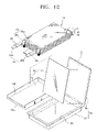
- FIGS. 11 , 12 , and 13 illustrate the state in which a second reinforcement member is closely adhered to an electrode assembly according to another embodiments of the present invention.
- FIG. 4 is an exploded perspective view of a pouch type secondary battery according to an embodiment of the present invention.
- an electrode assembly 40 is of a stacked type in which a plurality of bi-cell stacked structures each having positive and negative electrode plates 41 and 42 with a separator 43 interposed therebetween, are stacked.
- the stacked electrode assembly 40 shown in FIG. 4 is typically used in polymer lithium secondary batteries.
- the positive electrode plate 41 is formed by thermally compressing a positive electrode sheet containing a positive electrode active material comprising lithium oxide on at least one plane of a positive electrode current collector made of a metal foil, e.g., an aluminum foil.
- the negative electrode plate 42 is formed by thermally compressing a negative electrode sheet containing a negative electrode active material comprising a carbon material on at least one plane of a negative electrode current collector made of a metal foil, e.g., a copper foil.
- the electrode assembly 40 is housed in a pouch casing 30 , and an electrolytic solution is impregnated into the electrode assembly 40 , followed by sealing the pouch casing 30 , thereby forming a secondary battery.
- Electrode tabs 44 drawn from each of the electrode plates 41 and 42 are provided at one side of the stacked electrode assembly 40 , and electrode lead portions 45 are welded to the electrode tabs 44 .
- the positive electrode tabs 44 a are drawn from the positive electrode plate 41 and a positive electrode lead 45 a is welded to the positive electrode tabs 44 a .
- Negative electrode tabs 44 b are drawn from the negative electrode plate 42 and a negative electrode lead 45 b is welded to the negative electrode tabs 44 b .
- the positive and negative electrode leads 45 a and 45 b are exposed outside the pouch casing 30 even after being sealed, forming electrode terminals in cooperation with the electrode tabs 44 and the electrode lead portions 45 .
- a polymeric protective tape 46 for protecting the electrode terminals is adhered to the electrode lead portion 45 so that the electrode terminals are insulated from each other when the case body 32 and a pouch cover 34 are sealed.
- the electrode assembly may be a wound electrode assembly 50 where a positive electrode plate 51 and a negative electrode plate 52 are wound with a separator 53 interposed therebetween, as shown in FIG. 5 .
- the wound electrode assembly 50 shown in FIG. 5 is typically used in lithium ion batteries and is configured such that the separator 53 is interposed between the positive and negative electrode plates 51 and 52 and the resultant product is wound.
- the positive electrode plate 51 is formed by coating a positive electrode composite slurry containing a positive electrode active material, e.g., lithium oxide, on a positive electrode current collector made of a metal foil, e.g., an aluminum foil.
- the negative electrode plate 52 is formed by coating a negative electrode composite slurry containing a negative electrode active material, e.g., a carbon material, on a negative electrode current collector made of a metal foil, e.g., a copper foil.
- the wound electrode assembly 50 is housed in the pouch casing 30 and sealed except for an electrolytic solution injection hole. An electrolytic solution is injected through the electrolytic solution injection hole into the pouch casing and the electrolytic solution injection hole is sealed, thereby forming a secondary battery.
- Electrode tabs 54 are drawn from each of the electrode plates 51 and 52 of the wound electrode assembly 50 .
- Positive electrode tabs 54 a are drawn from the positive electrode plate 51 and negative electrode tabs 54 b are drawn from the negative electrode plate 52 .
- a polymeric protective tape 56 for protecting each of the electrode terminals is adhered to each of the positive and negative electrode tabs 54 a and 54 b , thereby forming positive and negative electrode terminals, respectively.
- a first reinforcement member 60 is closely adhered to at least one plane thereof and accommodated in a pouch casing 30 .
- the pouch casing 30 includes a case body 32 , recessed to accommodate the electrode assembly 40 or 50 , and a pouch cover 34 covering the case body 32 to be sealed.
- the shape of the pouch casing 30 is not particularly limited.
- a pouch casing having an opening in its one plane to be sealed may be used to accommodate an electrode assembly. In this case, a seal portion is provided.
- the invention will now be described with regard to the above-described pouch casing having a case body and a pouch cover.
- the invention has broad application to a variety configurations and is not limited to the embodiments described herein.
- the pouch casing 30 is preferably formed of a composite foil of a metallic material and a resin material. That is, the pouch casing 30 may be formed of a compressed composite material consisting of denatured polypropylene, e.g., cast polyproplylene (CPP), which is a thermally fusible polymer resin, inward with respect to a metal foil, e.g., an aluminum foil, and another CPP layer interposed between the metal foil and a resin material layer formed of nylon or polyethyleneterephthalate (PET).
- CPP cast polyproplylene
- PET polyethyleneterephthalate
- the first reinforcement member may be applied to both a stacked electrode assembly and a wound electrode assembly.
- the invention will be, for convenience, described with regard to the stacked electrode assembly.
- the features of the present invention are also applicable to the wound electrode assembly.
- a first reinforcement member 60 is closely adhered to at least one plane of the electrode assembly 40 .
- the first reinforcement member 60 is shaped of a panel so as to contact the upper face or bottom face of the electrode assembly 40 .
- the first reinforcement member may have a first layer 60 a made of a metal foil, e.g., aluminum, iron or stainless steel, and a second layer 60 b made of an adhesive resin material, e.g., CPP, on a plane of the first layer 60 a facing the electrode assembly 40 .
- the second layer 60 b may be formed by laminating an adhesive resin film on the first layer 60 a made of a metal foil, or coating an adhesive resin material thereon. Also, the second layer 60 b can be formed on the other plane of the first layer 60 a opposite to the plane facing the electrode assembly 40 .
- the above-described first reinforcement member 60 is tightly fixed to the electrode assembly 40 such that the second layer 60 b is adhered to the electrode assembly 40 .
- the second layer 60 b is formed of a thermally adhesive material as described above, thermal compression can be employed.
- the second layer 60 b made of a general adhesive resin can be adhered to the electrode assembly 40 simply by pressing the same onto the electrode assembly.
- the first layer 60 a may be formed of a fiber reinforced resin material rather than the metal foil.
- the first reinforcement member may be formed of a single material of either a metal foil or a fiber reinforced resin material.
- a first reinforcement member 61 may be fixed to the electrode assembly 40 using an insulating tape 62 .
- the first reinforcement member can be accommodated in a pouch case in a state in which it is in close proximity to the electrode assembly but does not contact the electrode assembly.
- a first reinforcement member 63 may be formed of an insulating tape to be adhered to at least one plane of the electrode assembly 40 .
- Such a first reinforcement member may have various shapes.
- the first reinforcement member may be formed on lateral surfaces of the electrode assembly 40 .
- the first reinforcement member is adhered to the electrode assembly 40 such that a lower reinforcement element 65 closely contacts the bottom surface, lateral surfaces and rear surface of the electrode assembly 40 , and an upper reinforcement element 64 closely contacts the upper surface of the electrode assembly 40 .
- an insulating tape may be wrapped around the first reinforcement member for fixedly adhering the reinforcement member to the electrode assembly 40 . Referring to FIG.
- the first reinforcement member may be thermally compressed to the electrode assembly 40 such that an upper reinforcement element 64 ′ closely contacts the upper surface and lateral surfaces of the electrode assembly 40 , and a lower reinforcement element 65 ′ closely contacts the bottom surface, lateral surfaces and rear surface of the electrode assembly 40 .
- the first reinforcement member may be fixed with the electrode assembly 40 using an insulating tape to then be closely adhered thereto.
- the upper and lower reinforcement members of the first reinforcement member may be formed of insulating tapes only.
- the first reinforcement member is closely adhered to planes of an electrode assembly, thereby more effectively protecting the electrode assembly against external impacts when the electrode assembly is accommodated in a pouch casing.
- the electrode assembly may become swollen due to swelling occurring during an initial charging and discharging period of a battery.
- a short-circuit may occur at the edges of an electrode assembly due to swelling of the electrode assembly. Swelling of the electrode assembly can be prevented by closely adhering the reinforcement member to the outer surfaces of the electrode assembly, thereby reducing a change in external dimensions due to swelling.
- FIGS. 10A , 10 B, 10 C, and 10 D illustrate a reinforcement member with an insulating tape adhered to the lateral planes of the electrode assembly 40 .
- a side insulating tape 66 is adhered to both lateral planes of the electrode assembly 40 .
- a rear insulating tape 67 is adhered to the rear plane of the electrode assembly 40 .
- FIG. 10B shows lateral insulating tape 66 , the invention is not limited thereto and may use only the rear insulating tape 67 .
- adhering insulating tape to the lateral planes of the electrode assembly 40 is particularly advantageous for a stacked electrode assembly.
- a stacked electrode assembly is prone to short-circuit between positive and negative electrodes due to swelling. Short-circuit at edges of the electrode assembly can be prevented by simply adhering an insulating tape to the lateral planes of the electrode assembly.
- the reinforcement member may have an insulating terminal cover 68 at the side where an electrode lead 45 is formed.
- the insulating terminal cover 68 may have insertion holes 68 a into which the electrode leads 45 are inserted.
- the insulating terminal cover 68 can be coupled to the front face of the electrode assembly 40 using a separate insulating tape 69 .
- the insulating terminal cover 68 allows the electrode lead 45 to be drawn out and protects the electrode tab 44 bent inside.
- the terminal cover 68 serves as both an insulator and a reinforcement member.
- the terminal cover 68 can be applied to the above-described previous embodiments of the present invention.
- a reinforcement member may be formed directly in a pouch case as well as at the electrode assembly.
- a pouch type secondary battery can be further reinforced by providing a second reinforcement member 70 closely adhered to at least one plane of internal faces of a pouch casing 30 where an electrode assembly is accommodated and sealed.
- the second reinforcement member 70 may have a bottom reinforcement element 72 adhered to the bottom of a case body 32 of the pouch casing 30 , and a top reinforcement element 71 adhered to the internal ceiling of the pouch casing 30 .
- the case body 32 and a pouch cover 34 of the pouch casing 30 are coupled to each other at a flange 33 of the case body 32 .
- the top reinforcement element 71 is not preferably adhered to a periphery 35 of the pouch cover 34 , corresponding to the flange 33 of the case body 33 .
- a bottom reinforcement element 73 may be formed such that it is closely adhered to the internal faces of the case body 32 , as shown in FIG. 12 .
- the height of a lateral plane 73 a at which electrode terminals are sealed is preferably smaller than that of the other plane 73 b.
- the second reinforcement member 70 can also be applied to a pouch casing 80 having a round bottom 82 a .
- a bottom reinforcement element 75 having the same shape as the round bottom 82 a is closely adhered to the bottom 82 a of the case body 82 .
- a reinforcement member can be provided at the front and/or rear planes of the pouch casing 80 .
- the second reinforcement member can be applied to any type of a pouch casing.
- the second reinforcement member may be formed of a shape corresponding to that of the internal face of the pouch casing and closely contacted thereto.
- the second reinforcement member can be formed of a metal foil, a fiber reinforced resin material or an insulating tape, and can be closely adhered to the internal face of the pouch casing by thermal compression using an adhesive resin, except for the insulating tape which has intrinsic adhesiveness.
- the present invention has the following advantages.
- the safety of a pouch type secondary battery against external impacts can be enhanced, thereby increasing the reliability of the battery.
- an reinforcing effect of a battery can be effectuated by a simple structure, thereby improving manufacturability.
Landscapes
- Chemical & Material Sciences (AREA)
- Chemical Kinetics & Catalysis (AREA)
- Electrochemistry (AREA)
- General Chemical & Material Sciences (AREA)
- Sealing Battery Cases Or Jackets (AREA)
- Secondary Cells (AREA)
Abstract
Description
Claims (15)
Priority Applications (2)
Application Number | Priority Date | Filing Date | Title |
---|---|---|---|
US12/761,983 US7947390B2 (en) | 2002-06-17 | 2010-04-16 | Reinforced pouch type secondary battery |
US13/113,519 US8133609B2 (en) | 2002-06-17 | 2011-05-23 | Reinforced pouch type secondary battery |
Applications Claiming Priority (2)
Application Number | Priority Date | Filing Date | Title |
---|---|---|---|
KR10-2002-0033721A KR100472504B1 (en) | 2002-06-17 | 2002-06-17 | Pouch type secondary battery with improved reinforcement structure |
KR2002-0033721 | 2002-06-17 |
Related Child Applications (1)
Application Number | Title | Priority Date | Filing Date |
---|---|---|---|
US12/761,983 Continuation US7947390B2 (en) | 2002-06-17 | 2010-04-16 | Reinforced pouch type secondary battery |
Publications (2)
Publication Number | Publication Date |
---|---|
US20040038125A1 US20040038125A1 (en) | 2004-02-26 |
US7722984B2 true US7722984B2 (en) | 2010-05-25 |
Family
ID=31884872
Family Applications (3)
Application Number | Title | Priority Date | Filing Date |
---|---|---|---|
US10/462,729 Expired - Lifetime US7722984B2 (en) | 2002-06-17 | 2003-06-17 | Reinforced pouch type secondary battery |
US12/761,983 Expired - Lifetime US7947390B2 (en) | 2002-06-17 | 2010-04-16 | Reinforced pouch type secondary battery |
US13/113,519 Expired - Fee Related US8133609B2 (en) | 2002-06-17 | 2011-05-23 | Reinforced pouch type secondary battery |
Family Applications After (2)
Application Number | Title | Priority Date | Filing Date |
---|---|---|---|
US12/761,983 Expired - Lifetime US7947390B2 (en) | 2002-06-17 | 2010-04-16 | Reinforced pouch type secondary battery |
US13/113,519 Expired - Fee Related US8133609B2 (en) | 2002-06-17 | 2011-05-23 | Reinforced pouch type secondary battery |
Country Status (2)
Country | Link |
---|---|
US (3) | US7722984B2 (en) |
KR (1) | KR100472504B1 (en) |
Cited By (16)
Publication number | Priority date | Publication date | Assignee | Title |
---|---|---|---|---|
US20070231701A1 (en) * | 2006-03-28 | 2007-10-04 | Sang-Ho Lee | Electrode assembly and pouch type lithium rechargeable battery having the same |
US20100099023A1 (en) * | 2006-10-23 | 2010-04-22 | Akira Kuroda | Assembled battery, manufacturing method of the same, and vehicle provided with assembled battery |
US20130149586A1 (en) * | 2011-12-09 | 2013-06-13 | Samsung Sdi Co., Ltd. | Battery cell |
US11063299B2 (en) | 2016-11-16 | 2021-07-13 | Enovix Corporation | Three-dimensional batteries with compressible cathodes |
US11081718B2 (en) | 2016-05-13 | 2021-08-03 | Enovix Corporation | Dimensional constraints for three-dimensional batteries |
US11127983B2 (en) | 2018-02-27 | 2021-09-21 | Samsung Electronics Co., Ltd. | Electronic device including battery structure |
US11128020B2 (en) | 2017-11-15 | 2021-09-21 | Enovix Corporation | Electrode assembly, secondary battery, and method of manufacture |
US11205803B2 (en) * | 2017-11-15 | 2021-12-21 | Enovix Corporation | Constrained electrode assembly |
US11211639B2 (en) | 2018-08-06 | 2021-12-28 | Enovix Corporation | Electrode assembly manufacture and device |
US11239488B2 (en) | 2015-05-14 | 2022-02-01 | Enovix Corporation | Longitudinal constraints for energy storage devices |
US11355816B2 (en) | 2013-03-15 | 2022-06-07 | Enovix Operations Inc. | Separators for three-dimensional batteries |
US11411253B2 (en) | 2020-12-09 | 2022-08-09 | Enovix Operations Inc. | Apparatus, systems and methods for the production of electrodes, electrode stacks and batteries |
US11495784B2 (en) | 2020-09-18 | 2022-11-08 | Enovix Operations Inc. | Apparatus, systems and methods for the production of electrodes for use in batteries |
US20220399612A1 (en) | 2021-06-15 | 2022-12-15 | Enovix Corporation | Spacers for providing protection of electrochemical battery enclosures and systems and methods therefor |
US11600848B2 (en) | 2012-08-16 | 2023-03-07 | Enovix Corporation | Electrode structures for three-dimensional batteries |
US11916207B2 (en) | 2017-10-11 | 2024-02-27 | Lg Energy Solution, Ltd. | Battery cell including sealing tape for accelerating heat conduction |
Families Citing this family (77)
Publication number | Priority date | Publication date | Assignee | Title |
---|---|---|---|---|
JP3831939B2 (en) * | 2001-11-12 | 2006-10-11 | ソニー株式会社 | battery |
JP4424053B2 (en) * | 2004-04-28 | 2010-03-03 | トヨタ自動車株式会社 | Laminated secondary battery and its assembled battery |
KR100591422B1 (en) * | 2004-07-30 | 2006-06-21 | 삼성에스디아이 주식회사 | Can type secondary battery |
KR100601511B1 (en) * | 2004-09-24 | 2006-07-19 | 삼성에스디아이 주식회사 | Lithium polymer battery and its manufacturing method |
KR100954031B1 (en) * | 2004-09-24 | 2010-04-20 | 삼성에스디아이 주식회사 | Secondary battery having jelly roll type electrode assembly |
US20060099501A1 (en) * | 2004-10-28 | 2006-05-11 | Kim Ka Y | Secondary battery |
KR100624953B1 (en) * | 2004-11-29 | 2006-09-18 | 삼성에스디아이 주식회사 | Lithium secondary battery |
KR101075349B1 (en) | 2005-09-06 | 2011-10-19 | 삼성에스디아이 주식회사 | Pouch type rechargeable battery |
KR100646500B1 (en) * | 2005-09-28 | 2006-11-14 | 삼성에스디아이 주식회사 | Electrode assembly for lithium rechargeable battery and lithium rechargeable battery using the same |
WO2007055479A1 (en) * | 2005-11-08 | 2007-05-18 | Lg Chem, Ltd. | Secondary battery with advanced safety |
JP4920957B2 (en) * | 2005-11-21 | 2012-04-18 | Necエナジーデバイス株式会社 | Stacked lithium ion polymer battery |
WO2007114542A1 (en) * | 2006-03-30 | 2007-10-11 | Lg Chem, Ltd. | Secondary battery of improved safety |
US8669003B2 (en) * | 2006-04-03 | 2014-03-11 | Lg Chem, Ltd. | Lithium secondary battery improved safety and capacity |
KR100906253B1 (en) * | 2006-05-01 | 2009-07-07 | 주식회사 엘지화학 | Secondary Battery Having Electrode With Self Cutting Part To Be Destructed On Application Of Over-Current |
KR100866767B1 (en) * | 2006-07-10 | 2008-11-04 | 주식회사 엘지화학 | Safety Kit for Secondary Battery |
KR100846972B1 (en) * | 2007-01-10 | 2008-07-17 | 삼성에스디아이 주식회사 | Hardcase for secondary battery and secondary battery using it |
KR100716596B1 (en) * | 2007-03-26 | 2007-05-09 | 새한에너테크 주식회사 | Pouch type lithium secondary battery |
KR100959090B1 (en) * | 2007-12-18 | 2010-05-20 | 주식회사 엘지화학 | Pouch type secondary battery with enhanced stability |
US8187752B2 (en) | 2008-04-16 | 2012-05-29 | Envia Systems, Inc. | High energy lithium ion secondary batteries |
WO2010009158A1 (en) * | 2008-07-14 | 2010-01-21 | A123 Systems, Inc. | Prismatic cell with outer electrode layers coated on a single side |
CN102084532A (en) * | 2009-03-31 | 2011-06-01 | 三菱重工业株式会社 | Secondary cell and cell system |
CN102047489A (en) * | 2009-03-31 | 2011-05-04 | 三菱重工业株式会社 | Secondary battery and battery system |
KR101419557B1 (en) * | 2009-08-07 | 2014-07-14 | 주식회사 엘지화학 | Large area battery for prevention of volume increment |
JP5363444B2 (en) * | 2009-10-01 | 2013-12-11 | 三星エスディアイ株式会社 | Secondary battery and manufacturing method thereof |
KR101108184B1 (en) * | 2009-12-11 | 2012-02-06 | 삼성에스디아이 주식회사 | Battery Pack |
DE102010004471A1 (en) * | 2010-01-13 | 2011-07-14 | Li-Tec Battery GmbH, 01917 | Frame for an electrochemical energy storage device |
US9331358B2 (en) | 2010-01-26 | 2016-05-03 | Apple Inc. | Battery with multiple jelly rolls in a single pouch |
US20110206976A1 (en) * | 2010-02-19 | 2011-08-25 | Kyung-Mo Yoo | Electrode assembly and secondary battery using the same |
EP2557626B1 (en) * | 2010-04-06 | 2015-02-25 | LG Chem, Ltd. | Stack-type cell, enhanced bi-cell, electrode assembly for secondary battery using same, and manufacturing method therefor |
KR101193171B1 (en) * | 2010-11-18 | 2012-10-19 | 삼성에스디아이 주식회사 | Battery pack |
KR101288532B1 (en) * | 2010-12-09 | 2013-07-26 | 지에스나노텍 주식회사 | The package of thin film battery |
JP5757730B2 (en) * | 2010-12-28 | 2015-07-29 | オートモーティブエナジーサプライ株式会社 | Film-clad battery, battery module, module assembly, method for producing film-clad battery, and electric vehicle |
KR101240718B1 (en) * | 2011-04-05 | 2013-03-11 | 삼성에스디아이 주식회사 | Case for secondary battery and secondary battery having the same |
US8709645B2 (en) * | 2011-07-01 | 2014-04-29 | Apple Inc. | Battery pouch sheet edge insulation |
KR101866369B1 (en) | 2011-07-12 | 2018-06-14 | 에스케이이노베이션 주식회사 | Battery case |
JP5917899B2 (en) * | 2011-11-29 | 2016-05-18 | 日産自動車株式会社 | Thin battery and method of manufacturing thin battery |
KR101914562B1 (en) * | 2011-12-09 | 2018-12-28 | 삼성에스디아이 주식회사 | Secondary battery |
KR101883913B1 (en) * | 2011-12-09 | 2018-08-01 | 삼성에스디아이 주식회사 | Secondary battery |
KR101905077B1 (en) * | 2012-01-19 | 2018-10-05 | 삼성에스디아이 주식회사 | Reinforcing material for battery cell and battery cell using the same |
KR101897223B1 (en) * | 2012-04-24 | 2018-09-12 | 에스케이이노베이션 주식회사 | Pouch type secondary battery |
US8808895B2 (en) * | 2012-06-22 | 2014-08-19 | Apple Inc. | Battery protection structures |
WO2014042400A1 (en) * | 2012-09-11 | 2014-03-20 | 주식회사 루트제이드 | Stacked type secondary battery |
TW201414046A (en) * | 2012-09-19 | 2014-04-01 | Dijiya Energy Saving Technology Inc | Structure of lithium battery |
KR101917350B1 (en) * | 2012-10-18 | 2018-11-09 | 에스케이이노베이션 주식회사 | The Secondary battery |
KR101414092B1 (en) | 2013-02-08 | 2014-07-04 | 주식회사 엘지화학 | Stepwise Electrode Assembly, Secondary Battery, Battery Pack and Devide comprising the Stepwise Electrode Assembly, and Method for preparing the Stepwise Electrode Assembly |
KR101996250B1 (en) * | 2013-06-21 | 2019-07-04 | 에스케이이노베이션 주식회사 | Secondary battery and secondary batter pack having the same |
KR102222112B1 (en) * | 2014-07-16 | 2021-03-03 | 삼성에스디아이 주식회사 | Flexible secondary battery |
KR102233779B1 (en) * | 2014-09-17 | 2021-03-30 | 삼성에스디아이 주식회사 | Secondary battery |
WO2016059514A1 (en) | 2014-10-17 | 2016-04-21 | Semiconductor Energy Laboratory Co., Ltd. | Electronic device |
JP2016085457A (en) | 2014-10-24 | 2016-05-19 | 株式会社半導体エネルギー研究所 | Electronic device |
JP6245142B2 (en) * | 2014-10-30 | 2017-12-13 | トヨタ自動車株式会社 | Secondary battery manufacturing method and secondary battery |
CN105633311B (en) * | 2014-11-21 | 2018-11-27 | 迪芬尼香港有限公司 | Battery module location structure and battery module |
US9819000B2 (en) * | 2014-11-21 | 2017-11-14 | Tymphany Worldwide Enterprises Limited | Battery module positioning structure and battery module |
JP6264663B2 (en) * | 2015-04-03 | 2018-01-24 | トヨタ自動車株式会社 | battery |
KR102504792B1 (en) * | 2015-10-16 | 2023-02-27 | 삼성에스디아이 주식회사 | Rechargeable battery |
KR102460962B1 (en) * | 2015-10-23 | 2022-10-31 | 삼성에스디아이 주식회사 | Secondary battery |
KR102479486B1 (en) * | 2015-10-28 | 2022-12-19 | 삼성에스디아이 주식회사 | Pouch type rechargeable battery |
KR102490864B1 (en) * | 2015-11-04 | 2023-01-20 | 삼성에스디아이 주식회사 | Secondary battery |
KR102580236B1 (en) | 2015-11-20 | 2023-09-19 | 삼성에스디아이 주식회사 | Secondary battery |
KR102149931B1 (en) * | 2015-11-30 | 2020-08-31 | 주식회사 엘지화학 | Secondary battery with relieved gas trap |
KR102074808B1 (en) * | 2015-12-10 | 2020-02-07 | 주식회사 엘지화학 | Electrode Assembly Comprising Electrode Plate Having Reinforcing Member Attached on One Side |
KR102319238B1 (en) | 2016-11-07 | 2021-10-28 | 삼성에스디아이 주식회사 | Rechargeable battery |
KR102227806B1 (en) * | 2017-01-25 | 2021-03-15 | 주식회사 엘지화학 | Secondary battery |
KR102137699B1 (en) | 2017-02-23 | 2020-07-24 | 주식회사 엘지화학 | Battery cell with bus bar |
KR102263444B1 (en) * | 2017-03-23 | 2021-06-11 | 주식회사 엘지에너지솔루션 | Battery Cell Comprising Receiving Frame |
JP7200131B2 (en) | 2017-04-24 | 2023-01-06 | エー123 システムズ エルエルシー | Structural embedding materials used to increase crush resistance |
CN110770956A (en) | 2017-06-15 | 2020-02-07 | A123系统有限责任公司 | Stacked prismatic architecture for electrochemical cells |
US10673028B2 (en) * | 2017-09-28 | 2020-06-02 | Maxwell Holdings, Ltd. | Electrochemical element |
US20190305303A1 (en) * | 2018-03-29 | 2019-10-03 | Lenovo (Singapore) Pte. Ltd. | Battery package |
US11355802B2 (en) * | 2019-04-26 | 2022-06-07 | Toyota Jidosha Kabushiki Kaisha | Secondary battery having improved manufacturability and performance |
KR20210021844A (en) * | 2019-08-19 | 2021-03-02 | 삼성에스디아이 주식회사 | Rechargeable battery |
KR102395231B1 (en) * | 2019-10-24 | 2022-05-04 | 주식회사 엘지에너지솔루션 | Battery cell and battery module including the same |
CN113314806B (en) * | 2020-02-07 | 2023-05-16 | 北京小米移动软件有限公司 | Composite battery and electronic device |
WO2021196028A1 (en) * | 2020-03-31 | 2021-10-07 | 宁德新能源科技有限公司 | Battery |
EP3863107A1 (en) * | 2020-08-19 | 2021-08-11 | Beijing Xiaomi Mobile Software Co., Ltd. | Composite battery and electronic device |
US20240030556A1 (en) * | 2021-10-12 | 2024-01-25 | Lg Energy Solution, Ltd. | Electrode Assembly |
WO2024063103A1 (en) * | 2022-09-22 | 2024-03-28 | 株式会社村田製作所 | Secondary battery |
Citations (6)
Publication number | Priority date | Publication date | Assignee | Title |
---|---|---|---|---|
US6042966A (en) * | 1998-01-20 | 2000-03-28 | Valence Technology, Inc. | Battery terminal insulation |
JP2000195475A (en) | 1998-12-25 | 2000-07-14 | Mitsubishi Chemicals Corp | Secondary battery |
JP2001005018A (en) | 1999-06-22 | 2001-01-12 | Casio Comput Co Ltd | Liquid crystal display device |
US20010051298A1 (en) * | 1999-05-14 | 2001-12-13 | Mitsubishi Denki Kabushiki Kaisha | Plate-shaped battery and battery apparatus |
US20030133254A1 (en) * | 2002-01-16 | 2003-07-17 | Zheng Chen | Light-weight reinforced electreochemical capacitor and process for making the same |
US6743546B1 (en) * | 1999-03-26 | 2004-06-01 | Matsushita Electric Industrial Co., Ltd. | Laminate sheath type battery |
Family Cites Families (6)
Publication number | Priority date | Publication date | Assignee | Title |
---|---|---|---|---|
JPH10214606A (en) * | 1996-11-28 | 1998-08-11 | Sanyo Electric Co Ltd | Thin type battery of laminated armor body |
JP2000357536A (en) * | 1999-06-15 | 2000-12-26 | Japan Storage Battery Co Ltd | Nonaqueous electrolyte battery |
KR100573097B1 (en) * | 1999-06-30 | 2006-04-24 | 삼성에스디아이 주식회사 | secondary battery |
JP2001283798A (en) * | 2000-03-29 | 2001-10-12 | Sanyo Electric Co Ltd | Battery with laminated armor |
JP4821043B2 (en) * | 2000-11-08 | 2011-11-24 | Tdk株式会社 | Electrochemical devices |
DE10226848A1 (en) * | 2002-06-15 | 2003-12-24 | Varta Microbattery Gmbh | Galvanic element |
-
2002
- 2002-06-17 KR KR10-2002-0033721A patent/KR100472504B1/en active IP Right Grant
-
2003
- 2003-06-17 US US10/462,729 patent/US7722984B2/en not_active Expired - Lifetime
-
2010
- 2010-04-16 US US12/761,983 patent/US7947390B2/en not_active Expired - Lifetime
-
2011
- 2011-05-23 US US13/113,519 patent/US8133609B2/en not_active Expired - Fee Related
Patent Citations (6)
Publication number | Priority date | Publication date | Assignee | Title |
---|---|---|---|---|
US6042966A (en) * | 1998-01-20 | 2000-03-28 | Valence Technology, Inc. | Battery terminal insulation |
JP2000195475A (en) | 1998-12-25 | 2000-07-14 | Mitsubishi Chemicals Corp | Secondary battery |
US6743546B1 (en) * | 1999-03-26 | 2004-06-01 | Matsushita Electric Industrial Co., Ltd. | Laminate sheath type battery |
US20010051298A1 (en) * | 1999-05-14 | 2001-12-13 | Mitsubishi Denki Kabushiki Kaisha | Plate-shaped battery and battery apparatus |
JP2001005018A (en) | 1999-06-22 | 2001-01-12 | Casio Comput Co Ltd | Liquid crystal display device |
US20030133254A1 (en) * | 2002-01-16 | 2003-07-17 | Zheng Chen | Light-weight reinforced electreochemical capacitor and process for making the same |
Cited By (32)
Publication number | Priority date | Publication date | Assignee | Title |
---|---|---|---|---|
US7858240B2 (en) * | 2006-03-28 | 2010-12-28 | Samsung Sdi Co., Ltd. | Electrode assembly and pouch type lithium rechargeable battery having the same |
US20070231701A1 (en) * | 2006-03-28 | 2007-10-04 | Sang-Ho Lee | Electrode assembly and pouch type lithium rechargeable battery having the same |
US20100099023A1 (en) * | 2006-10-23 | 2010-04-22 | Akira Kuroda | Assembled battery, manufacturing method of the same, and vehicle provided with assembled battery |
US8435667B2 (en) * | 2006-10-23 | 2013-05-07 | Toyota Jidosha Kabushiki Kaisha | Assembled battery, manufacturing method of the same, and vehicle provided with assembled battery |
US20130149586A1 (en) * | 2011-12-09 | 2013-06-13 | Samsung Sdi Co., Ltd. | Battery cell |
CN103165847A (en) * | 2011-12-09 | 2013-06-19 | 三星Sdi株式会社 | Battery cell |
CN103165847B (en) * | 2011-12-09 | 2017-05-10 | 三星Sdi株式会社 | Battery cell |
US12009473B2 (en) | 2012-08-16 | 2024-06-11 | Enovix Corporation | Electrode structures for three-dimensional batteries |
US11600848B2 (en) | 2012-08-16 | 2023-03-07 | Enovix Corporation | Electrode structures for three-dimensional batteries |
US11355816B2 (en) | 2013-03-15 | 2022-06-07 | Enovix Operations Inc. | Separators for three-dimensional batteries |
US11239488B2 (en) | 2015-05-14 | 2022-02-01 | Enovix Corporation | Longitudinal constraints for energy storage devices |
US11894512B2 (en) | 2015-05-14 | 2024-02-06 | Enovix Corporation | Longitudinal constraints for energy storage devices |
US11081718B2 (en) | 2016-05-13 | 2021-08-03 | Enovix Corporation | Dimensional constraints for three-dimensional batteries |
US11444310B2 (en) | 2016-05-13 | 2022-09-13 | Enovix Operations Inc. | Dimensional constraints for three-dimensional batteries |
US11961952B2 (en) | 2016-05-13 | 2024-04-16 | Enovix Corporation | Dimensional constraints for three-dimensional batteries |
US11901514B2 (en) | 2016-11-16 | 2024-02-13 | Enovix Corporation | Three-dimensional batteries with compressible cathodes |
US11063299B2 (en) | 2016-11-16 | 2021-07-13 | Enovix Corporation | Three-dimensional batteries with compressible cathodes |
US11916207B2 (en) | 2017-10-11 | 2024-02-27 | Lg Energy Solution, Ltd. | Battery cell including sealing tape for accelerating heat conduction |
US11600864B2 (en) | 2017-11-15 | 2023-03-07 | Enovix Corporation | Constrained electrode assembly |
US11264680B2 (en) * | 2017-11-15 | 2022-03-01 | Enovix Corporation | Electrode assembly and secondary battery |
US12095040B2 (en) | 2017-11-15 | 2024-09-17 | Enovix Corporation | Constrained electrode assembly |
US11128020B2 (en) | 2017-11-15 | 2021-09-21 | Enovix Corporation | Electrode assembly, secondary battery, and method of manufacture |
US12087947B2 (en) | 2017-11-15 | 2024-09-10 | Enovix Corporation | Electrode assembly, secondary battery, and method of manufacture |
US11205803B2 (en) * | 2017-11-15 | 2021-12-21 | Enovix Corporation | Constrained electrode assembly |
US11127983B2 (en) | 2018-02-27 | 2021-09-21 | Samsung Electronics Co., Ltd. | Electronic device including battery structure |
US11211639B2 (en) | 2018-08-06 | 2021-12-28 | Enovix Corporation | Electrode assembly manufacture and device |
US11495784B2 (en) | 2020-09-18 | 2022-11-08 | Enovix Operations Inc. | Apparatus, systems and methods for the production of electrodes for use in batteries |
US11811047B2 (en) | 2020-09-18 | 2023-11-07 | Enovix Corporation | Apparatus, systems and methods for the production of electrodes for use in batteries |
US12095072B2 (en) | 2020-09-18 | 2024-09-17 | Enovix Corporation | Apparatus, systems and methods for the production of electrodes for use in batteries |
US11411253B2 (en) | 2020-12-09 | 2022-08-09 | Enovix Operations Inc. | Apparatus, systems and methods for the production of electrodes, electrode stacks and batteries |
US20220399612A1 (en) | 2021-06-15 | 2022-12-15 | Enovix Corporation | Spacers for providing protection of electrochemical battery enclosures and systems and methods therefor |
US11699830B2 (en) | 2021-06-15 | 2023-07-11 | Enovix Operations Inc. | Spacers for providing protection of electrochemical battery enclosures and systems and methods therefor |
Also Published As
Publication number | Publication date |
---|---|
US7947390B2 (en) | 2011-05-24 |
US20100203381A1 (en) | 2010-08-12 |
US20040038125A1 (en) | 2004-02-26 |
US20110223474A1 (en) | 2011-09-15 |
KR100472504B1 (en) | 2005-03-10 |
US8133609B2 (en) | 2012-03-13 |
KR20030096717A (en) | 2003-12-31 |
Similar Documents
Publication | Publication Date | Title |
---|---|---|
US7722984B2 (en) | Reinforced pouch type secondary battery | |
US7410723B2 (en) | Pouch type secondary battery | |
KR100891383B1 (en) | Pouch type secondary battery | |
US7122276B2 (en) | Pouch type secondary battery with safety vent | |
KR100790631B1 (en) | Film enclosed electric device and collector covering member for the film enclosed electric device | |
KR100496305B1 (en) | Pouched-type lithium secondary battery and the fabrication method thereof | |
JP5254332B2 (en) | Large capacity battery pack | |
US7618737B2 (en) | Lithium secondary battery and method for manufacturing the same | |
KR100601548B1 (en) | Secondary battery | |
KR100778982B1 (en) | Pouch case and pouch type secondary battery employing the same | |
KR101146465B1 (en) | Pouch type secondary battery and the fabrication method thereof | |
KR100515833B1 (en) | Jelly-roll type electrode assembly and secondary battery applying the same | |
KR100918408B1 (en) | Pouch type secondary battery | |
KR100670438B1 (en) | Pouch type lithium secondary battery | |
KR100601549B1 (en) | Pouch type lithium secondary battery | |
KR20040107868A (en) | Pouched-type lithium secondary battery | |
KR20220033944A (en) | The Electrode Assembly And The Secondary Battery | |
KR100838064B1 (en) | Lithium secondary battery | |
EP4258461A1 (en) | Pouch-type secondary battery and manufacturing method therefor | |
KR20060034508A (en) | Pouch type lithium secondary battery | |
KR20070109082A (en) | Pouch type lithium secondary battery | |
CN116686162A (en) | Pouch type secondary battery and method for manufacturing the same | |
JP2013152935A (en) | Large capacity battery pack |
Legal Events
Date | Code | Title | Description |
---|---|---|---|
AS | Assignment |
Owner name: SAMSUNG SDI CO., LTD., KOREA, REPUBLIC OF Free format text: ASSIGNMENT OF ASSIGNORS INTEREST;ASSIGNORS:KIM, SANG-BUM;KIM, CHANG-HO;HAN, WON-CHULL;AND OTHERS;REEL/FRAME:014183/0241 Effective date: 20030603 Owner name: SAMSUNG SDI CO., LTD.,KOREA, REPUBLIC OF Free format text: ASSIGNMENT OF ASSIGNORS INTEREST;ASSIGNORS:KIM, SANG-BUM;KIM, CHANG-HO;HAN, WON-CHULL;AND OTHERS;REEL/FRAME:014183/0241 Effective date: 20030603 |
|
FEPP | Fee payment procedure |
Free format text: PAYOR NUMBER ASSIGNED (ORIGINAL EVENT CODE: ASPN); ENTITY STATUS OF PATENT OWNER: LARGE ENTITY |
|
STCF | Information on status: patent grant |
Free format text: PATENTED CASE |
|
FPAY | Fee payment |
Year of fee payment: 4 |
|
MAFP | Maintenance fee payment |
Free format text: PAYMENT OF MAINTENANCE FEE, 8TH YEAR, LARGE ENTITY (ORIGINAL EVENT CODE: M1552) Year of fee payment: 8 |
|
MAFP | Maintenance fee payment |
Free format text: PAYMENT OF MAINTENANCE FEE, 12TH YEAR, LARGE ENTITY (ORIGINAL EVENT CODE: M1553); ENTITY STATUS OF PATENT OWNER: LARGE ENTITY Year of fee payment: 12 |