US7721877B2 - Quick splice conveyor belt system and method therefor - Google Patents
Quick splice conveyor belt system and method therefor Download PDFInfo
- Publication number
- US7721877B2 US7721877B2 US12/326,950 US32695008A US7721877B2 US 7721877 B2 US7721877 B2 US 7721877B2 US 32695008 A US32695008 A US 32695008A US 7721877 B2 US7721877 B2 US 7721877B2
- Authority
- US
- United States
- Prior art keywords
- rod
- edge
- conveyor belt
- rods
- links
- Prior art date
- Legal status (The legal status is an assumption and is not a legal conclusion. Google has not performed a legal analysis and makes no representation as to the accuracy of the status listed.)
- Active
Links
Images


Classifications
-
- B—PERFORMING OPERATIONS; TRANSPORTING
- B65—CONVEYING; PACKING; STORING; HANDLING THIN OR FILAMENTARY MATERIAL
- B65G—TRANSPORT OR STORAGE DEVICES, e.g. CONVEYORS FOR LOADING OR TIPPING, SHOP CONVEYOR SYSTEMS OR PNEUMATIC TUBE CONVEYORS
- B65G17/00—Conveyors having an endless traction element, e.g. a chain, transmitting movement to a continuous or substantially-continuous load-carrying surface or to a series of individual load-carriers; Endless-chain conveyors in which the chains form the load-carrying surface
- B65G17/06—Conveyors having an endless traction element, e.g. a chain, transmitting movement to a continuous or substantially-continuous load-carrying surface or to a series of individual load-carriers; Endless-chain conveyors in which the chains form the load-carrying surface having a load-carrying surface formed by a series of interconnected, e.g. longitudinal, links, plates, or platforms
- B65G17/08—Conveyors having an endless traction element, e.g. a chain, transmitting movement to a continuous or substantially-continuous load-carrying surface or to a series of individual load-carriers; Endless-chain conveyors in which the chains form the load-carrying surface having a load-carrying surface formed by a series of interconnected, e.g. longitudinal, links, plates, or platforms the surface being formed by the traction element
-
- B—PERFORMING OPERATIONS; TRANSPORTING
- B65—CONVEYING; PACKING; STORING; HANDLING THIN OR FILAMENTARY MATERIAL
- B65G—TRANSPORT OR STORAGE DEVICES, e.g. CONVEYORS FOR LOADING OR TIPPING, SHOP CONVEYOR SYSTEMS OR PNEUMATIC TUBE CONVEYORS
- B65G2207/00—Indexing codes relating to constructional details, configuration and additional features of a handling device, e.g. Conveyors
- B65G2207/12—Chain pin retainers
-
- Y—GENERAL TAGGING OF NEW TECHNOLOGICAL DEVELOPMENTS; GENERAL TAGGING OF CROSS-SECTIONAL TECHNOLOGIES SPANNING OVER SEVERAL SECTIONS OF THE IPC; TECHNICAL SUBJECTS COVERED BY FORMER USPC CROSS-REFERENCE ART COLLECTIONS [XRACs] AND DIGESTS
- Y10—TECHNICAL SUBJECTS COVERED BY FORMER USPC
- Y10T—TECHNICAL SUBJECTS COVERED BY FORMER US CLASSIFICATION
- Y10T29/00—Metal working
- Y10T29/49—Method of mechanical manufacture
- Y10T29/49826—Assembling or joining
- Y10T29/49947—Assembling or joining by applying separate fastener
Definitions
- the present invention is directed to a conveyor belt, more particularly to a conveyor belt having a preformed splice rod, and still more particularly, to a conveyor belt system having specially sized openings in the conveyor belt components to receive the splice rod therethrough.
- a grid conveyor belt includes a plurality of spaced transverse rods slidably interconnected by at least two rows of U-shaped connecting links, i.e., the tension bearing members, disposed respectively along the inner and outer edges of the rods.
- the terminal ends of the transverse rods are formed into enlarged heads or button heads which retain the links on the rods and welds are then provided to secure the link to the button head and to the rod, thereby preventing rotational movement of the links on the transverse rods.
- the connecting links are disposed in a nested relationship relative to one another with slots being provided in the links in order to slidably receive the transverse rods.
- Grid conveyor belts of this type have met with overwhelming market approval because of their ability to travel in straight line conveyor paths as well as in curved conveyor paths, thus making grid conveyor belts ideal for use on spiral cage conveyors.
- the presence of the button head ends and welded ends requires the use of special tools such as a grinder and bolt cutter and welding in order to part an endless belt or to reconnect or splice two separate ends of a belt.
- special threaded connector rods with end nuts have to be used to replace the rods with the button head ends when performing repair/maintenance in the field.
- Flat wire conveyor belts have also been in the market for many years, as shown for example in U.S. Pat. No. 2,619,306, the contents of which are hereby incorporated by reference.
- Flat wire conveyor belts are generally low maintenance and when positively driven with sprockets have little to no lateral shifting.
- a flat wire conveyor belt 10 comprising a plurality of pickets 12 , sometimes also referred to as wickets, and interconnecting rods 14 about which the pickets hinge.
- the pickets of the belt define the tension bearing members and support the product to be conveyed and the rods are utilized to hold the components of belt together.
- This type of flat wire conveyor belts also utilize upset rod ends 16 , i.e., button head shaped ends, for rod retention.
- upset rod ends 16 i.e., button head shaped ends
- the compression between the pickets keep them from moving inward of the button head ends, while the button head ends prevent the pickets from moving outwardly.
- Flat wire conveyor belts of this type can also be used in both straight and turn applications.
- a second type of flat wire conveyor belt 10 ′ as shown in FIG. 2 , utilizes mechanically clinched rod ends 16 ′ for rod retention. These type of belts are used only in straight run applications.
- a conveyor belt system including a splice rod having a j-shaped hook on each end thereof and a plurality of links for receiving the splice rod therethrough.
- the links further include a specially modified link end for securing the rods.
- a further aspect of the invention is directed to a conveyor belt comprising a plurality of spaced tractive rods; a plurality of rows of flat wire wickets transversely disposed with respect to a direction of travel and interconnecting said plurality of spaced tractive rods, wherein at least one of said rows of flat wire wickets includes an outer edge link on each end thereof, said outer edge link including a projecting tab on an outer side thereof; and wherein at least one of said plurality of rods includes a hooked shaped end on each end thereof, at least one hooked shaped end of said at least one rod engaging the projecting tab on one said outer edge link.
- the present invention encompasses a method of manufacturing a conveyor belt.
- the method comprises providing a plurality of transverse rods including a hooked shaped end on each end thereof; providing a plurality of wickets or links having a first pair of openings extending laterally therethrough and a second pair of openings extending therethrough, said outermost edge wickets or links including a projecting extension; and arranging the transverse rods through the first and second pair of openings so as to pivotally interconnect the transverse rods in a longitudinally spaced arrangement; wherein said hooked shaped ends of said rods engage the projecting extensions on said outermost wickets or links.
- FIG. 1 is a perspective view of a segment of a conventional flat wire conveyor belt.
- FIG. 2 is a perspective view of a segment of a second type of conventional flat wire conveyor belt.
- FIG. 3 is a top elevational view of a flat wire conveyor belt according to a preferred embodiment of the present invention.
- FIG. 4 is a side elevational view of the flat wire conveyor belt shown in FIG. 3 .
- FIG. 5 is a perspective view of the flat wire conveyor belt shown in FIG. 3 .
- FIG. 6 is a partial enlarged perspective view of the flat wire conveyor belt shown in FIG. 5 .
- FIG. 7 is a partial enlarged elevational view of the flat wire conveyor belt shown in FIG. 3 .
- FIG. 8 is a perspective view of a link in a grid type conveyor belt with the connector rod partially installed in accordance with a further preferred embodiment of the invention.
- FIG. 9 is an elevational view thereof.
- FIG. 10 is a perspective view of a link in a grid type conveyor belt with the connector rod fully installed.
- FIG. 11 is an elevational view thereof.
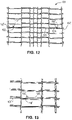
- FIG. 12 is a top elevational view of a flat wire conveyor belt according to a further preferred embodiment of the present invention.
- FIG. 13 is a partial top elevational view of the flat wire conveyor belt shown in FIG. 12 .
- FIG. 14 is a partial perspective view of the flat wire conveyor belt shown in FIG. 12 .
- Conveyor belt 100 preferably comprises a flat wire conveyor belt including a plurality of spaced tractive rods 102 disposed in succession and transversely with respect to a direction of travel, each rod 102 having two ends 104 and 106 .
- Belt 100 includes a plurality of rows of pickets 108 transversely disposed with respect to the direction of travel, and interconnecting the succession of rods 102 .
- Each row of pickets 108 is comprised of a plurality of links 110 , each link connecting a rod 108 with a following rod 108 in the succession.
- rods 102 include a special connecting “J” rod for splicing together two ends of a conveyor belt.
- the rods 102 are pre-formed with a “J” shaped hook 112 on each end 104 , 106 .
- the links 110 include openings 114 proximal each terminal end which define slots sized to allow the J-shape hook 112 on the ends 104 , 106 of the rod 102 to pass freely through the pickets 108 .
- the outer ends 116 of the picket are modified to form a projecting tab 118 .
- conveyor belt 100 ′ includes two edge rods 102 ′ including the special connecting “J” shaped hook 112 ′ on each end and a center splice rod 120 including the special “J” shaped hook 112 ′ on both ends 122 , 124 .
- the links 110 include openings 114 proximal each terminal end which define slots sized to allow the J-shape hook 112 ′ on the ends of the rod 102 ′ to pass freely through the pickets 108 .
- the outer ends 116 of the picket are modified to form a projecting tab 118 ( FIG. 6 ).
- the edge rods 102 ′ engage the outer ends 116 of the pickets on one end thereof and the opposite ends of the edge rods 102 ′ connect to the opposing ends 122 , 124 of center rod 120 in the center of the conveyor belt, or at some other location remote from the conveyor belt edge.
- the center rod 120 thereby connects to the two edge rods 102 ′ to form one continuous splice rod.
- the pickets of the belts are aligned in succession and a first edge rod 102 ′ is inserted from an intermediate opening or interior position of the belt towards a first outside edge of the belt in the direction of arrow B ( FIG. 14 ) through the link openings 114 of the respective rows of pickets 108 .
- the outer edge j-shaped end (not shown) is hooked or snapped onto the projecting tab 118 on the end 116 of the picket 108 , either by hand or through the use of a simple pair of pliers, as described above relative to the first preferred embodiment.
- the other edge rod 102 ′ is inserted in a similar manner on the opposite side of the conveyor belt and in the opposite direction towards a second outside edge of the belt.
- the center rod 120 is inserted from the intermediate opening on one side of the belt towards the other intermediate opening on the opposite side of the belt.
- the j-shaped ends 122 , 124 of the center rod 120 each connect with a corresponding j-shaped end of the opposing edge rods 102 ′. Upon connection of the j-shaped ends, the splice is thereby complete.
- a grid style conveyor belt such as that described above and disclosed in U.S. Pat. No. 6,354,432, has tension bearing members mounted only on the ends of the connecting rods, and thus has a slightly modified splicing system in accordance with a third embodiment of the present invention.
- a grid style conveyor belt includes a plurality of spaced transverse rods 202 slidably interconnected by a row of U-shaped connecting links 210 disposed respectively along each end 204 of the rod.
- rods 202 include a special connecting “J” rod for splicing together two ends of a conveyor belt.
- the rods 202 are pre-formed with a “J” shaped hook 212 on each end.
- the links 210 include a pair of longitudinally extending legs including openings 214 proximal each terminal end which define slots sized to allow the J-shape hook 212 on the ends of the rod 202 to pass freely through the links 210 .
- the outermost ends 216 of the outer legs of links 210 are modified to form a hole 218 in an extension of the link for receiving the end of the J-shaped hook 212 on the rod 202 and to be bent around the rod after it inserted into the hole.
- the links 210 of the belts are aligned in succession and a splice rod 202 is inserted in the direction of arrow A through the link openings 214 (only one belt being shown in FIGS. 8 and 9 ).
- the j-shaped ends 204 are hooked or snapped into the holes 218 on the end 216 of the link 210 , generally by hand. Thereafter, the link ends 216 are bent upwards around the end of the rod using of a simple pair of pliers in order to secure the rod.
Landscapes
- Engineering & Computer Science (AREA)
- Mechanical Engineering (AREA)
- Belt Conveyors (AREA)
- Chain Conveyers (AREA)
Priority Applications (1)
| Application Number | Priority Date | Filing Date | Title |
|---|---|---|---|
| US12/326,950 US7721877B2 (en) | 2007-12-03 | 2008-12-03 | Quick splice conveyor belt system and method therefor |
Applications Claiming Priority (2)
| Application Number | Priority Date | Filing Date | Title |
|---|---|---|---|
| US99673307P | 2007-12-03 | 2007-12-03 | |
| US12/326,950 US7721877B2 (en) | 2007-12-03 | 2008-12-03 | Quick splice conveyor belt system and method therefor |
Publications (2)
| Publication Number | Publication Date |
|---|---|
| US20090145732A1 US20090145732A1 (en) | 2009-06-11 |
| US7721877B2 true US7721877B2 (en) | 2010-05-25 |
Family
ID=40718036
Family Applications (1)
| Application Number | Title | Priority Date | Filing Date |
|---|---|---|---|
| US12/326,950 Active US7721877B2 (en) | 2007-12-03 | 2008-12-03 | Quick splice conveyor belt system and method therefor |
Country Status (7)
| Country | Link |
|---|---|
| US (1) | US7721877B2 (pt) |
| EP (1) | EP2220396B1 (pt) |
| CN (1) | CN101910676B (pt) |
| ES (1) | ES2545084T3 (pt) |
| PL (1) | PL2220396T3 (pt) |
| PT (1) | PT2220396E (pt) |
| WO (1) | WO2009073166A1 (pt) |
Cited By (30)
| Publication number | Priority date | Publication date | Assignee | Title |
|---|---|---|---|---|
| JPH0859485A (ja) * | 1994-08-26 | 1996-03-05 | Sanwa Kagaku Kenkyusho Co Ltd | 3ーオキシゲルミルプロピオン酸化合物を主成分とするメイラード反応阻害剤 |
| US20090242360A1 (en) * | 2005-05-13 | 2009-10-01 | Ramsey Products Corporation | End protector link for conveyor chain |
| US20100282577A1 (en) * | 2009-05-08 | 2010-11-11 | Alit S.R.L. | Link of a side chain for conveyor belts |
| US20120037480A1 (en) * | 2008-01-29 | 2012-02-16 | Frans Bakker Beheer B.V. | Conveyor Belt |
| US20130092513A1 (en) * | 2011-09-20 | 2013-04-18 | Wire Belt Company Of America | Flat wire conveyor belt with multiple connecting rods and strengthening edges |
| US8474607B2 (en) | 2010-11-19 | 2013-07-02 | Ramsey Products Corporation | Integrated multi-functional links for chain link conveyor and method |
| WO2014103887A1 (ja) * | 2012-12-27 | 2014-07-03 | 株式会社前川製作所 | 食品搬送用コンベア装置 |
| US20150129395A1 (en) * | 2013-11-08 | 2015-05-14 | Cambridge International Inc. | Varvariable spaced conveyor belt with clinched rod ends |
| US20150151919A1 (en) * | 2013-11-27 | 2015-06-04 | Cambridge International Inc. | Variable width drive openings for conveyor belt |
| USD739110S1 (en) | 2014-06-09 | 2015-09-15 | Cambridge International Inc. | Mesh panel |
| US9428340B2 (en) | 2014-04-23 | 2016-08-30 | ContiTech Transport band systeme GMBH | Conveyor belt with zero stage splice |
| US20180000284A1 (en) * | 2016-06-29 | 2018-01-04 | Prince Castle LLC | Continuous conveyor belt for food heating device |
| US9884694B2 (en) | 2012-09-19 | 2018-02-06 | Mat Processing, Llc | Rear discharge mat rolling machine with wrapper |
| US9889992B1 (en) | 2015-05-13 | 2018-02-13 | Prince Castle LLC | Conveyor belt slat |
| US9901213B2 (en) | 2015-09-10 | 2018-02-27 | Prince Castle LLC | Modular food holding system |
| US9908708B1 (en) | 2015-05-13 | 2018-03-06 | Prince Castle LLC | Conveyor belt link with coupling mechanism |
| US9962038B2 (en) | 2015-09-10 | 2018-05-08 | Prince Castle LLC | Modular food holding system |
| US10118766B2 (en) | 2016-03-10 | 2018-11-06 | Cambridge International, Inc. | Splice link for conveyor belt |
| US10154757B2 (en) | 2015-09-10 | 2018-12-18 | Prince Castle LLC | Modular food holding system |
| US10271689B2 (en) | 2015-09-10 | 2019-04-30 | Prince Castle LLC | Modular food holding system |
| US10308433B2 (en) | 2016-06-29 | 2019-06-04 | Prince Castle LLC | Conveyor belt slat with side carrier connection |
| US10315847B2 (en) | 2014-12-31 | 2019-06-11 | Prince Castle LLC | Extruded slat/link conveyance chain |
| US10455983B2 (en) | 2015-09-10 | 2019-10-29 | Prince Castle LLC | Modular food holding system |
| US10464757B2 (en) | 2014-12-31 | 2019-11-05 | Prince Castle LLC | Sprocket driven conveyor belt link and conveyor belt assembly |
| US10723560B2 (en) | 2016-11-18 | 2020-07-28 | Prince Castle LLC | Side-by-side snap on slats for a chain conveyor belt and conveyor belt system comprising same |
| US10723558B2 (en) | 2016-01-27 | 2020-07-28 | Prince Castle LLC | Snap on slat for a chain conveyor belt and conveyor belt system comprising same |
| US10843871B2 (en) | 2017-12-01 | 2020-11-24 | Prince Castle LLC | Side-by-side slats for a chain conveyor belt and conveyor belt system comprising same |
| US10941834B2 (en) | 2018-01-30 | 2021-03-09 | Cambridge International, Inc. | Splice system for conveyor belt |
| US11022197B2 (en) | 2018-10-11 | 2021-06-01 | Flexible Steel Lacing Company | Fastener for cable conveyor belt |
| US11185191B2 (en) | 2016-05-20 | 2021-11-30 | Marmon Foodservice Technologies, Inc. | Modular food holding system |
Families Citing this family (3)
| Publication number | Priority date | Publication date | Assignee | Title |
|---|---|---|---|---|
| US8960587B2 (en) | 2011-05-27 | 2015-02-24 | Umana Family Corporation | Rear discharge mat rolling machine |
| USD826577S1 (en) * | 2017-08-16 | 2018-08-28 | Quantum Materials, Llc | Woven fabric |
| US20240083681A1 (en) * | 2022-09-13 | 2024-03-14 | Cambridge International, Inc. | Weldless Conveyor Belt Systems and Methods |
Citations (11)
| Publication number | Priority date | Publication date | Assignee | Title |
|---|---|---|---|---|
| US2619306A (en) * | 1949-11-01 | 1952-11-25 | United States Steel Corp | Flat wire conveyer belt |
| US3176358A (en) | 1962-07-18 | 1965-04-06 | Leflon Henry Eugene | Fasteners for conveyor belts and the like |
| US4754871A (en) * | 1987-10-05 | 1988-07-05 | Wire Belt Company Of America | Wire mesh belt and splicer |
| US4944716A (en) | 1988-08-19 | 1990-07-31 | Gkd Gebr. Kufferath Gmbh & Co. Kg | Wire netting belt |
| US4957597A (en) * | 1989-09-20 | 1990-09-18 | I. J. White Co. | Conveyor belt for turn conveyors |
| US5954187A (en) | 1996-01-22 | 1999-09-21 | Cambridge, Inc. | Conveyor rod in side link connection |
| US6102196A (en) | 1998-01-19 | 2000-08-15 | Wire Belt Company Of America | Wire link connection system and method |
| US6202833B1 (en) * | 1997-02-20 | 2001-03-20 | Wire Belt Company Of America | Conveyor belt with variable spacing |
| US6325205B1 (en) * | 1999-05-03 | 2001-12-04 | Sollich Kg | Apparatus for conveying articles |
| US6354432B1 (en) * | 1999-06-18 | 2002-03-12 | Cambridge, Inc. | Conveyor belt and method of making the same |
| US6371284B1 (en) * | 1998-12-18 | 2002-04-16 | Johan Hendrik | Device for conveying objects |
Family Cites Families (5)
| Publication number | Priority date | Publication date | Assignee | Title |
|---|---|---|---|---|
| GB107044A (pt) * | ||||
| US2963144A (en) * | 1956-04-26 | 1960-12-06 | Helix Corp | Conveyor belt |
| CN2106815U (zh) * | 1991-09-24 | 1992-06-10 | 周平非 | D形卡钩 |
| US5566817A (en) * | 1995-05-31 | 1996-10-22 | Meeker; William A. | Conveyor belt |
| CN200961056Y (zh) * | 2006-10-10 | 2007-10-17 | 张民良 | 高强度钩式链节的链索及其刮板组件 |
-
2008
- 2008-12-02 PT PT88561980T patent/PT2220396E/pt unknown
- 2008-12-02 WO PCT/US2008/013266 patent/WO2009073166A1/en active Application Filing
- 2008-12-02 CN CN2008801234998A patent/CN101910676B/zh active Active
- 2008-12-02 ES ES08856198.0T patent/ES2545084T3/es active Active
- 2008-12-02 PL PL08856198T patent/PL2220396T3/pl unknown
- 2008-12-02 EP EP08856198.0A patent/EP2220396B1/en active Active
- 2008-12-03 US US12/326,950 patent/US7721877B2/en active Active
Patent Citations (11)
| Publication number | Priority date | Publication date | Assignee | Title |
|---|---|---|---|---|
| US2619306A (en) * | 1949-11-01 | 1952-11-25 | United States Steel Corp | Flat wire conveyer belt |
| US3176358A (en) | 1962-07-18 | 1965-04-06 | Leflon Henry Eugene | Fasteners for conveyor belts and the like |
| US4754871A (en) * | 1987-10-05 | 1988-07-05 | Wire Belt Company Of America | Wire mesh belt and splicer |
| US4944716A (en) | 1988-08-19 | 1990-07-31 | Gkd Gebr. Kufferath Gmbh & Co. Kg | Wire netting belt |
| US4957597A (en) * | 1989-09-20 | 1990-09-18 | I. J. White Co. | Conveyor belt for turn conveyors |
| US5954187A (en) | 1996-01-22 | 1999-09-21 | Cambridge, Inc. | Conveyor rod in side link connection |
| US6202833B1 (en) * | 1997-02-20 | 2001-03-20 | Wire Belt Company Of America | Conveyor belt with variable spacing |
| US6102196A (en) | 1998-01-19 | 2000-08-15 | Wire Belt Company Of America | Wire link connection system and method |
| US6371284B1 (en) * | 1998-12-18 | 2002-04-16 | Johan Hendrik | Device for conveying objects |
| US6325205B1 (en) * | 1999-05-03 | 2001-12-04 | Sollich Kg | Apparatus for conveying articles |
| US6354432B1 (en) * | 1999-06-18 | 2002-03-12 | Cambridge, Inc. | Conveyor belt and method of making the same |
Cited By (47)
| Publication number | Priority date | Publication date | Assignee | Title |
|---|---|---|---|---|
| JPH0859485A (ja) * | 1994-08-26 | 1996-03-05 | Sanwa Kagaku Kenkyusho Co Ltd | 3ーオキシゲルミルプロピオン酸化合物を主成分とするメイラード反応阻害剤 |
| US20090242360A1 (en) * | 2005-05-13 | 2009-10-01 | Ramsey Products Corporation | End protector link for conveyor chain |
| US7802675B2 (en) * | 2005-05-13 | 2010-09-28 | Ramsey Products Corporation | End protector link for conveyor chain |
| US20120037480A1 (en) * | 2008-01-29 | 2012-02-16 | Frans Bakker Beheer B.V. | Conveyor Belt |
| US8544638B2 (en) * | 2008-01-29 | 2013-10-01 | Hennie Hermanus Jozef Meulenkamp | Conveyor belt |
| US20100282577A1 (en) * | 2009-05-08 | 2010-11-11 | Alit S.R.L. | Link of a side chain for conveyor belts |
| US8474607B2 (en) | 2010-11-19 | 2013-07-02 | Ramsey Products Corporation | Integrated multi-functional links for chain link conveyor and method |
| US20130092513A1 (en) * | 2011-09-20 | 2013-04-18 | Wire Belt Company Of America | Flat wire conveyor belt with multiple connecting rods and strengthening edges |
| US8739966B2 (en) * | 2011-09-20 | 2014-06-03 | Wire Belt Company Of America | Flat wire conveyor belt with multiple connecting rods and strengthening edges |
| US9884694B2 (en) | 2012-09-19 | 2018-02-06 | Mat Processing, Llc | Rear discharge mat rolling machine with wrapper |
| JP2017014019A (ja) * | 2012-12-27 | 2017-01-19 | 株式会社前川製作所 | 食品搬送用コンベア装置 |
| US9540176B2 (en) | 2012-12-27 | 2017-01-10 | Mayekawa Mfg. Co., Ltd. | Conveyor device for conveying food |
| WO2014103887A1 (ja) * | 2012-12-27 | 2014-07-03 | 株式会社前川製作所 | 食品搬送用コンベア装置 |
| JPWO2014103887A1 (ja) * | 2012-12-27 | 2017-01-12 | 株式会社前川製作所 | 食品搬送用コンベア装置 |
| US20150129395A1 (en) * | 2013-11-08 | 2015-05-14 | Cambridge International Inc. | Varvariable spaced conveyor belt with clinched rod ends |
| US9475642B2 (en) * | 2013-11-08 | 2016-10-25 | Cambridge International Inc. | Variable spaced conveyor belt with clinched rod ends |
| US9169074B2 (en) * | 2013-11-27 | 2015-10-27 | Cambridge International, Inc. | Variable width drive openings for conveyor belt |
| US20150151919A1 (en) * | 2013-11-27 | 2015-06-04 | Cambridge International Inc. | Variable width drive openings for conveyor belt |
| US9428340B2 (en) | 2014-04-23 | 2016-08-30 | ContiTech Transport band systeme GMBH | Conveyor belt with zero stage splice |
| USD739110S1 (en) | 2014-06-09 | 2015-09-15 | Cambridge International Inc. | Mesh panel |
| US10464757B2 (en) | 2014-12-31 | 2019-11-05 | Prince Castle LLC | Sprocket driven conveyor belt link and conveyor belt assembly |
| US10315847B2 (en) | 2014-12-31 | 2019-06-11 | Prince Castle LLC | Extruded slat/link conveyance chain |
| US10173844B2 (en) | 2015-05-13 | 2019-01-08 | Prince Castle LLC | Conveyor belt link with coupling mechanism |
| US9889992B1 (en) | 2015-05-13 | 2018-02-13 | Prince Castle LLC | Conveyor belt slat |
| US9908708B1 (en) | 2015-05-13 | 2018-03-06 | Prince Castle LLC | Conveyor belt link with coupling mechanism |
| US10273089B2 (en) | 2015-05-13 | 2019-04-30 | Prince Castle LLC | Conveyor belt slat |
| US9901213B2 (en) | 2015-09-10 | 2018-02-27 | Prince Castle LLC | Modular food holding system |
| US10154757B2 (en) | 2015-09-10 | 2018-12-18 | Prince Castle LLC | Modular food holding system |
| US10213052B2 (en) | 2015-09-10 | 2019-02-26 | Prince Castle LLC | Modular food holding system |
| US10271689B2 (en) | 2015-09-10 | 2019-04-30 | Prince Castle LLC | Modular food holding system |
| US11344156B2 (en) | 2015-09-10 | 2022-05-31 | Marmon Foodservice Technologies, Inc | Modular food holding system |
| US9962038B2 (en) | 2015-09-10 | 2018-05-08 | Prince Castle LLC | Modular food holding system |
| US10455983B2 (en) | 2015-09-10 | 2019-10-29 | Prince Castle LLC | Modular food holding system |
| US10723558B2 (en) | 2016-01-27 | 2020-07-28 | Prince Castle LLC | Snap on slat for a chain conveyor belt and conveyor belt system comprising same |
| US10118766B2 (en) | 2016-03-10 | 2018-11-06 | Cambridge International, Inc. | Splice link for conveyor belt |
| US11185191B2 (en) | 2016-05-20 | 2021-11-30 | Marmon Foodservice Technologies, Inc. | Modular food holding system |
| US10494182B2 (en) | 2016-06-29 | 2019-12-03 | Prince Castle LLC | Conveyor belt slat with side carrier connection |
| US10494183B2 (en) | 2016-06-29 | 2019-12-03 | Prince Castle LLC | Conveyor belt slat with side carrier connection |
| US10486908B2 (en) | 2016-06-29 | 2019-11-26 | Prince Castle LLC | Conveyor belt slat with side carrier connection |
| US20180000284A1 (en) * | 2016-06-29 | 2018-01-04 | Prince Castle LLC | Continuous conveyor belt for food heating device |
| US10308433B2 (en) | 2016-06-29 | 2019-06-04 | Prince Castle LLC | Conveyor belt slat with side carrier connection |
| US10723560B2 (en) | 2016-11-18 | 2020-07-28 | Prince Castle LLC | Side-by-side snap on slats for a chain conveyor belt and conveyor belt system comprising same |
| US10843871B2 (en) | 2017-12-01 | 2020-11-24 | Prince Castle LLC | Side-by-side slats for a chain conveyor belt and conveyor belt system comprising same |
| US10941834B2 (en) | 2018-01-30 | 2021-03-09 | Cambridge International, Inc. | Splice system for conveyor belt |
| US11493110B2 (en) | 2018-01-30 | 2022-11-08 | Cambridge International, Inc. | Splice system for conveyor belt |
| US11022197B2 (en) | 2018-10-11 | 2021-06-01 | Flexible Steel Lacing Company | Fastener for cable conveyor belt |
| US11713796B2 (en) | 2018-10-11 | 2023-08-01 | Flexible Steel Lacing Company | Fastener for cable conveyor belt |
Also Published As
| Publication number | Publication date |
|---|---|
| US20090145732A1 (en) | 2009-06-11 |
| ES2545084T3 (es) | 2015-09-08 |
| PL2220396T3 (pl) | 2015-11-30 |
| EP2220396A4 (en) | 2014-01-08 |
| PT2220396E (pt) | 2015-10-09 |
| EP2220396A1 (en) | 2010-08-25 |
| WO2009073166A1 (en) | 2009-06-11 |
| CN101910676A (zh) | 2010-12-08 |
| CN101910676B (zh) | 2013-07-17 |
| EP2220396B1 (en) | 2015-08-05 |
Similar Documents
| Publication | Publication Date | Title |
|---|---|---|
| US7721877B2 (en) | Quick splice conveyor belt system and method therefor | |
| US9475642B2 (en) | Variable spaced conveyor belt with clinched rod ends | |
| US5954187A (en) | Conveyor rod in side link connection | |
| US11493110B2 (en) | Splice system for conveyor belt | |
| US8701876B2 (en) | Clips for attaching staples for joining conveyor belt ends and clip-staple assemblies | |
| EP1559665A1 (en) | Plate conveyer chain with anti-shingling top plates | |
| US10577183B2 (en) | Edge drive mesh overlay conveyor belt | |
| US4754871A (en) | Wire mesh belt and splicer | |
| JP2006160525A (ja) | リンク機構により結合された部材を有する側屈コンベアチェーン | |
| US7284657B2 (en) | Modular conveyor belt with unique link capture means | |
| EP2758691B1 (en) | Flat wire conveyor belt with multiple part connecting rods and strengthening edges | |
| EP3080016A1 (en) | Conveyor chain module | |
| US6530469B2 (en) | Wire belt with compound link formation | |
| US6360882B1 (en) | Conveyor belt and method of making the same | |
| EP0502639B1 (en) | Replaceable snap-on modular overlay for rod and link turn-curve conveyor belts | |
| US20140048392A1 (en) | Link member having a curved bearing surface | |
| US7954631B1 (en) | Chain link conveyor for use in material handling equipment | |
| US10118766B2 (en) | Splice link for conveyor belt | |
| US10308432B2 (en) | Insert for wire mesh belts | |
| US20240083681A1 (en) | Weldless Conveyor Belt Systems and Methods | |
| US4487013A (en) | T-rod chain | |
| US11718480B1 (en) | Chain conveyor paddle attachment bracket | |
| US1839072A (en) | Link conveyer belt | |
| US8646304B2 (en) | Grain bin floor panel |
Legal Events
| Date | Code | Title | Description |
|---|---|---|---|
| AS | Assignment |
Owner name: CAMBRIDGE INTERNATIONAL, INC., MARYLAND Free format text: ASSIGNMENT OF ASSIGNORS INTEREST;ASSIGNORS:MAINE, ROBERT E., JR.;MESSICK, GEORGE HOWARD, JR.;HENNIGAR, CHARLES;AND OTHERS;REEL/FRAME:022265/0436 Effective date: 20090213 Owner name: CAMBRIDGE INTERNATIONAL, INC.,MARYLAND Free format text: ASSIGNMENT OF ASSIGNORS INTEREST;ASSIGNORS:MAINE, ROBERT E., JR.;MESSICK, GEORGE HOWARD, JR.;HENNIGAR, CHARLES;AND OTHERS;REEL/FRAME:022265/0436 Effective date: 20090213 |
|
| STCF | Information on status: patent grant |
Free format text: PATENTED CASE |
|
| AS | Assignment |
Owner name: GENERAL ELECTRIC CAPITAL CORPORATION, AS ADMINISTR Free format text: SECURITY AGREEMENT;ASSIGNOR:CAMBRIDGE INTERNATIONAL, INC.;REEL/FRAME:028028/0851 Effective date: 20120410 |
|
| FPAY | Fee payment |
Year of fee payment: 4 |
|
| AS | Assignment |
Owner name: CAMBRIDGE INTERNATIONAL, INC., MARYLAND Free format text: RELEASE BY SECURED PARTY;ASSIGNOR:GENERAL ELECTRIC COMPANY (AS SUCCESSOR IN INTEREST BY MERGER TO GENERAL ELECTRIC CAPITAL CORPORATION);REEL/FRAME:037482/0958 Effective date: 20160113 Owner name: ANTARES CAPITAL LP, AS ADMINISTRATIVE AGENT, ILLIN Free format text: SECURITY INTEREST;ASSIGNOR:CAMBRIDGE INTERNATIONAL, INC.;REEL/FRAME:037508/0945 Effective date: 20160113 |
|
| AS | Assignment |
Owner name: CAMBRIDGE INTERNATIONAL, INC., MARYLAND Free format text: RELEASE BY SECURED PARTY;ASSIGNOR:ANTARES CAPITAL LP, AS ADMINISTRATIVE AGENT;REEL/FRAME:040491/0710 Effective date: 20160601 |
|
| AS | Assignment |
Owner name: CREDIT SUISSE AG, CAYMAN ISLANDS BRANCH, NEW YORK Free format text: INTELLECTUAL PROPERTY SECURITY AGREEMENT;ASSIGNOR:CAMBRIDGE INTERNATIONAL INC.;REEL/FRAME:040556/0001 Effective date: 20161102 |
|
| MAFP | Maintenance fee payment |
Free format text: PAYMENT OF MAINTENANCE FEE, 8TH YR, SMALL ENTITY (ORIGINAL EVENT CODE: M2552) Year of fee payment: 8 |
|
| FEPP | Fee payment procedure |
Free format text: ENTITY STATUS SET TO UNDISCOUNTED (ORIGINAL EVENT CODE: BIG.); ENTITY STATUS OF PATENT OWNER: LARGE ENTITY |
|
| AS | Assignment |
Owner name: CAMBRIDGE INTERNATIONAL, INC., MARYLAND Free format text: RELEASE BY SECURED PARTY;ASSIGNOR:CREDIT SUISSE AG, CAYMAN ISLANDS BRANCH, AS ADMINISTRATIVE AGENT AND COLLATERAL AGENT;REEL/FRAME:057966/0319 Effective date: 20211004 Owner name: SANITARY-DASH MANUFACTURING CO., INC., PENNSYLVANIA Free format text: RELEASE BY SECURED PARTY;ASSIGNOR:CREDIT SUISSE AG, CAYMAN ISLANDS BRANCH, AS ADMINISTRATIVE AGENT AND COLLATERAL AGENT;REEL/FRAME:057966/0319 Effective date: 20211004 Owner name: REXNORD INDUSTRIES, LLC, WISCONSIN Free format text: RELEASE BY SECURED PARTY;ASSIGNOR:CREDIT SUISSE AG, CAYMAN ISLANDS BRANCH, AS ADMINISTRATIVE AGENT AND COLLATERAL AGENT;REEL/FRAME:057966/0319 Effective date: 20211004 |
|
| MAFP | Maintenance fee payment |
Free format text: PAYMENT OF MAINTENANCE FEE, 12TH YEAR, LARGE ENTITY (ORIGINAL EVENT CODE: M1553); ENTITY STATUS OF PATENT OWNER: LARGE ENTITY Year of fee payment: 12 |