US7721349B1 - Flexible personal evaporative cooling system with warming potential - Google Patents
Flexible personal evaporative cooling system with warming potential Download PDFInfo
- Publication number
- US7721349B1 US7721349B1 US11/166,675 US16667505A US7721349B1 US 7721349 B1 US7721349 B1 US 7721349B1 US 16667505 A US16667505 A US 16667505A US 7721349 B1 US7721349 B1 US 7721349B1
- Authority
- US
- United States
- Prior art keywords
- user
- elements
- skin
- reservoir
- fluid
- Prior art date
- Legal status (The legal status is an assumption and is not a legal conclusion. Google has not performed a legal analysis and makes no representation as to the accuracy of the status listed.)
- Expired - Fee Related, expires
Links
- 238000001816 cooling Methods 0.000 title claims abstract description 130
- 238000010792 warming Methods 0.000 title abstract description 16
- 239000012530 fluid Substances 0.000 claims abstract description 71
- 238000001704 evaporation Methods 0.000 claims abstract description 27
- 241001465754 Metazoa Species 0.000 claims abstract description 21
- 230000004888 barrier function Effects 0.000 claims description 95
- 230000009471 action Effects 0.000 claims description 22
- 238000009736 wetting Methods 0.000 claims description 19
- 210000004209 hair Anatomy 0.000 claims description 15
- 239000000126 substance Substances 0.000 claims description 14
- 230000001737 promoting effect Effects 0.000 claims description 5
- 239000000463 material Substances 0.000 abstract description 66
- 238000000034 method Methods 0.000 abstract description 18
- 230000008020 evaporation Effects 0.000 abstract description 13
- 239000012809 cooling fluid Substances 0.000 abstract description 6
- 238000009413 insulation Methods 0.000 abstract description 4
- 230000032258 transport Effects 0.000 abstract description 3
- XLYOFNOQVPJJNP-UHFFFAOYSA-N water Substances O XLYOFNOQVPJJNP-UHFFFAOYSA-N 0.000 description 136
- 230000000694 effects Effects 0.000 description 40
- 239000004744 fabric Substances 0.000 description 38
- 230000014509 gene expression Effects 0.000 description 33
- 238000013459 approach Methods 0.000 description 27
- 239000010410 layer Substances 0.000 description 27
- 239000002250 absorbent Substances 0.000 description 22
- 230000002745 absorbent Effects 0.000 description 21
- XAGFODPZIPBFFR-UHFFFAOYSA-N aluminium Chemical compound [Al] XAGFODPZIPBFFR-UHFFFAOYSA-N 0.000 description 21
- 210000003128 head Anatomy 0.000 description 20
- 229910052782 aluminium Inorganic materials 0.000 description 19
- 230000006870 function Effects 0.000 description 17
- 230000001681 protective effect Effects 0.000 description 16
- 230000008901 benefit Effects 0.000 description 15
- 239000004033 plastic Substances 0.000 description 11
- 229920003023 plastic Polymers 0.000 description 11
- 239000007921 spray Substances 0.000 description 11
- 210000001061 forehead Anatomy 0.000 description 9
- 210000004761 scalp Anatomy 0.000 description 9
- 238000000576 coating method Methods 0.000 description 8
- 239000006260 foam Substances 0.000 description 8
- 241000282472 Canis lupus familiaris Species 0.000 description 7
- 239000007788 liquid Substances 0.000 description 7
- 239000011248 coating agent Substances 0.000 description 6
- 239000004020 conductor Substances 0.000 description 6
- 238000013461 design Methods 0.000 description 6
- 239000003292 glue Substances 0.000 description 6
- 230000033001 locomotion Effects 0.000 description 6
- 239000000843 powder Substances 0.000 description 6
- 150000003839 salts Chemical class 0.000 description 6
- 238000012546 transfer Methods 0.000 description 6
- 229920002334 Spandex Polymers 0.000 description 5
- 230000008859 change Effects 0.000 description 5
- 230000005484 gravity Effects 0.000 description 5
- 239000003595 mist Substances 0.000 description 5
- 230000005855 radiation Effects 0.000 description 5
- 239000004759 spandex Substances 0.000 description 5
- 230000000087 stabilizing effect Effects 0.000 description 5
- 239000000725 suspension Substances 0.000 description 5
- 241000282412 Homo Species 0.000 description 4
- 229920001971 elastomer Polymers 0.000 description 4
- 239000000835 fiber Substances 0.000 description 4
- -1 foamed Substances 0.000 description 4
- 239000012212 insulator Substances 0.000 description 4
- 230000000149 penetrating effect Effects 0.000 description 4
- 230000008569 process Effects 0.000 description 4
- 238000005507 spraying Methods 0.000 description 4
- 238000004804 winding Methods 0.000 description 4
- 230000015572 biosynthetic process Effects 0.000 description 3
- 210000000245 forearm Anatomy 0.000 description 3
- 239000007789 gas Substances 0.000 description 3
- 239000000499 gel Substances 0.000 description 3
- 239000008187 granular material Substances 0.000 description 3
- 239000007787 solid Substances 0.000 description 3
- 238000003860 storage Methods 0.000 description 3
- 125000000391 vinyl group Chemical group [H]C([*])=C([H])[H] 0.000 description 3
- 229920002554 vinyl polymer Polymers 0.000 description 3
- 230000000007 visual effect Effects 0.000 description 3
- RYGMFSIKBFXOCR-UHFFFAOYSA-N Copper Chemical compound [Cu] RYGMFSIKBFXOCR-UHFFFAOYSA-N 0.000 description 2
- 229920000742 Cotton Polymers 0.000 description 2
- PXHVJJICTQNCMI-UHFFFAOYSA-N Nickel Chemical compound [Ni] PXHVJJICTQNCMI-UHFFFAOYSA-N 0.000 description 2
- 239000004677 Nylon Substances 0.000 description 2
- 241000719239 Oligoplites altus Species 0.000 description 2
- 206010042496 Sunburn Diseases 0.000 description 2
- 239000000654 additive Substances 0.000 description 2
- 238000004026 adhesive bonding Methods 0.000 description 2
- 150000001298 alcohols Chemical class 0.000 description 2
- 239000000956 alloy Substances 0.000 description 2
- 229910045601 alloy Inorganic materials 0.000 description 2
- 239000011324 bead Substances 0.000 description 2
- 239000011230 binding agent Substances 0.000 description 2
- 230000000903 blocking effect Effects 0.000 description 2
- 238000004891 communication Methods 0.000 description 2
- 229910052802 copper Inorganic materials 0.000 description 2
- 239000010949 copper Substances 0.000 description 2
- 238000001514 detection method Methods 0.000 description 2
- 238000009826 distribution Methods 0.000 description 2
- 238000009760 electrical discharge machining Methods 0.000 description 2
- 238000002474 experimental method Methods 0.000 description 2
- 239000003205 fragrance Substances 0.000 description 2
- 239000000446 fuel Substances 0.000 description 2
- 238000010438 heat treatment Methods 0.000 description 2
- 239000010985 leather Substances 0.000 description 2
- 230000005923 long-lasting effect Effects 0.000 description 2
- 238000004519 manufacturing process Methods 0.000 description 2
- 229920001778 nylon Polymers 0.000 description 2
- 239000003921 oil Substances 0.000 description 2
- 239000011148 porous material Substances 0.000 description 2
- 238000007789 sealing Methods 0.000 description 2
- 239000004094 surface-active agent Substances 0.000 description 2
- 230000009452 underexpressoin Effects 0.000 description 2
- 210000000707 wrist Anatomy 0.000 description 2
- 241000251468 Actinopterygii Species 0.000 description 1
- 206010006797 Burns first degree Diseases 0.000 description 1
- 241000255925 Diptera Species 0.000 description 1
- LFQSCWFLJHTTHZ-UHFFFAOYSA-N Ethanol Chemical compound CCO LFQSCWFLJHTTHZ-UHFFFAOYSA-N 0.000 description 1
- JOYRKODLDBILNP-UHFFFAOYSA-N Ethyl urethane Chemical compound CCOC(N)=O JOYRKODLDBILNP-UHFFFAOYSA-N 0.000 description 1
- 241000238631 Hexapoda Species 0.000 description 1
- UFHFLCQGNIYNRP-UHFFFAOYSA-N Hydrogen Chemical compound [H][H] UFHFLCQGNIYNRP-UHFFFAOYSA-N 0.000 description 1
- 239000004698 Polyethylene Substances 0.000 description 1
- 239000004743 Polypropylene Substances 0.000 description 1
- 206010037660 Pyrexia Diseases 0.000 description 1
- CDBYLPFSWZWCQE-UHFFFAOYSA-L Sodium Carbonate Chemical compound [Na+].[Na+].[O-]C([O-])=O CDBYLPFSWZWCQE-UHFFFAOYSA-L 0.000 description 1
- 208000027418 Wounds and injury Diseases 0.000 description 1
- 241000607479 Yersinia pestis Species 0.000 description 1
- 238000005299 abrasion Methods 0.000 description 1
- 230000002411 adverse Effects 0.000 description 1
- 238000004378 air conditioning Methods 0.000 description 1
- 230000000844 anti-bacterial effect Effects 0.000 description 1
- 230000003466 anti-cipated effect Effects 0.000 description 1
- 230000000845 anti-microbial effect Effects 0.000 description 1
- 239000004760 aramid Substances 0.000 description 1
- 210000000617 arm Anatomy 0.000 description 1
- 238000000222 aromatherapy Methods 0.000 description 1
- 229920003235 aromatic polyamide Polymers 0.000 description 1
- 230000000386 athletic effect Effects 0.000 description 1
- 238000003287 bathing Methods 0.000 description 1
- 230000009286 beneficial effect Effects 0.000 description 1
- 230000004397 blinking Effects 0.000 description 1
- 238000005219 brazing Methods 0.000 description 1
- 230000001413 cellular effect Effects 0.000 description 1
- KYKAJFCTULSVSH-UHFFFAOYSA-N chloro(fluoro)methane Chemical compound F[C]Cl KYKAJFCTULSVSH-UHFFFAOYSA-N 0.000 description 1
- GVPFVAHMJGGAJG-UHFFFAOYSA-L cobalt dichloride Chemical compound [Cl-].[Cl-].[Co+2] GVPFVAHMJGGAJG-UHFFFAOYSA-L 0.000 description 1
- 239000003086 colorant Substances 0.000 description 1
- 239000002131 composite material Substances 0.000 description 1
- 235000009508 confectionery Nutrition 0.000 description 1
- 238000010276 construction Methods 0.000 description 1
- 239000002826 coolant Substances 0.000 description 1
- 230000034994 death Effects 0.000 description 1
- 231100000517 death Toxicity 0.000 description 1
- 238000011161 development Methods 0.000 description 1
- 238000007598 dipping method Methods 0.000 description 1
- 201000010099 disease Diseases 0.000 description 1
- 208000037265 diseases, disorders, signs and symptoms Diseases 0.000 description 1
- 230000035622 drinking Effects 0.000 description 1
- 239000013013 elastic material Substances 0.000 description 1
- 238000005485 electric heating Methods 0.000 description 1
- 238000005516 engineering process Methods 0.000 description 1
- 238000005530 etching Methods 0.000 description 1
- 239000004715 ethylene vinyl alcohol Substances 0.000 description 1
- 229920002457 flexible plastic Polymers 0.000 description 1
- 244000144992 flock Species 0.000 description 1
- 239000013505 freshwater Substances 0.000 description 1
- 238000009963 fulling Methods 0.000 description 1
- 239000003517 fume Substances 0.000 description 1
- 239000011521 glass Substances 0.000 description 1
- 210000004247 hand Anatomy 0.000 description 1
- 231100001261 hazardous Toxicity 0.000 description 1
- 239000000383 hazardous chemical Substances 0.000 description 1
- 230000036541 health Effects 0.000 description 1
- 230000008821 health effect Effects 0.000 description 1
- RZXDTJIXPSCHCI-UHFFFAOYSA-N hexa-1,5-diene-2,5-diol Chemical compound OC(=C)CCC(O)=C RZXDTJIXPSCHCI-UHFFFAOYSA-N 0.000 description 1
- 229930195733 hydrocarbon Natural products 0.000 description 1
- 150000002430 hydrocarbons Chemical class 0.000 description 1
- 239000001257 hydrogen Substances 0.000 description 1
- 229910052739 hydrogen Inorganic materials 0.000 description 1
- 239000004615 ingredient Substances 0.000 description 1
- 239000000976 ink Substances 0.000 description 1
- 239000002648 laminated material Substances 0.000 description 1
- 238000003698 laser cutting Methods 0.000 description 1
- 229920000126 latex Polymers 0.000 description 1
- 239000004816 latex Substances 0.000 description 1
- 230000007774 longterm Effects 0.000 description 1
- 230000007246 mechanism Effects 0.000 description 1
- 201000001441 melanoma Diseases 0.000 description 1
- 229910052751 metal Inorganic materials 0.000 description 1
- 239000002184 metal Substances 0.000 description 1
- 238000005459 micromachining Methods 0.000 description 1
- 230000005012 migration Effects 0.000 description 1
- 238000013508 migration Methods 0.000 description 1
- 239000000203 mixture Substances 0.000 description 1
- 238000012544 monitoring process Methods 0.000 description 1
- 210000003739 neck Anatomy 0.000 description 1
- 229910052759 nickel Inorganic materials 0.000 description 1
- 231100000252 nontoxic Toxicity 0.000 description 1
- 230000003000 nontoxic effect Effects 0.000 description 1
- 239000004745 nonwoven fabric Substances 0.000 description 1
- 230000008520 organization Effects 0.000 description 1
- 238000005192 partition Methods 0.000 description 1
- 239000008188 pellet Substances 0.000 description 1
- 229920002401 polyacrylamide Polymers 0.000 description 1
- 229920000573 polyethylene Polymers 0.000 description 1
- 229920001155 polypropylene Polymers 0.000 description 1
- 238000007639 printing Methods 0.000 description 1
- 238000005086 pumping Methods 0.000 description 1
- 230000002285 radioactive effect Effects 0.000 description 1
- 230000003014 reinforcing effect Effects 0.000 description 1
- 238000005067 remediation Methods 0.000 description 1
- 230000029058 respiratory gaseous exchange Effects 0.000 description 1
- 230000000284 resting effect Effects 0.000 description 1
- 238000005096 rolling process Methods 0.000 description 1
- 238000005488 sandblasting Methods 0.000 description 1
- 230000035807 sensation Effects 0.000 description 1
- 238000009958 sewing Methods 0.000 description 1
- HBMJWWWQQXIZIP-UHFFFAOYSA-N silicon carbide Chemical compound [Si+]#[C-] HBMJWWWQQXIZIP-UHFFFAOYSA-N 0.000 description 1
- 229910010271 silicon carbide Inorganic materials 0.000 description 1
- 239000002356 single layer Substances 0.000 description 1
- 239000007779 soft material Substances 0.000 description 1
- 238000005476 soldering Methods 0.000 description 1
- 239000011343 solid material Substances 0.000 description 1
- 239000002904 solvent Substances 0.000 description 1
- 125000006850 spacer group Chemical group 0.000 description 1
- 210000004243 sweat Anatomy 0.000 description 1
- 239000012780 transparent material Substances 0.000 description 1
- 238000011282 treatment Methods 0.000 description 1
- 238000009423 ventilation Methods 0.000 description 1
- 238000004078 waterproofing Methods 0.000 description 1
- 238000003466 welding Methods 0.000 description 1
- 210000002268 wool Anatomy 0.000 description 1
- 230000003245 working effect Effects 0.000 description 1
- 239000002759 woven fabric Substances 0.000 description 1
Images


Classifications
-
- A—HUMAN NECESSITIES
- A41—WEARING APPAREL
- A41D—OUTERWEAR; PROTECTIVE GARMENTS; ACCESSORIES
- A41D13/00—Professional, industrial or sporting protective garments, e.g. surgeons' gowns or garments protecting against blows or punches
- A41D13/002—Professional, industrial or sporting protective garments, e.g. surgeons' gowns or garments protecting against blows or punches with controlled internal environment
- A41D13/005—Professional, industrial or sporting protective garments, e.g. surgeons' gowns or garments protecting against blows or punches with controlled internal environment with controlled temperature
- A41D13/0053—Cooled garments
-
- A—HUMAN NECESSITIES
- A42—HEADWEAR
- A42B—HATS; HEAD COVERINGS
- A42B1/00—Hats; Caps; Hoods
- A42B1/008—Hats; Caps; Hoods with means for heating or cooling
-
- A—HUMAN NECESSITIES
- A42—HEADWEAR
- A42B—HATS; HEAD COVERINGS
- A42B3/00—Helmets; Helmet covers ; Other protective head coverings
- A42B3/04—Parts, details or accessories of helmets
- A42B3/28—Ventilating arrangements
- A42B3/285—Ventilating arrangements with additional heating or cooling means
-
- A—HUMAN NECESSITIES
- A43—FOOTWEAR
- A43B—CHARACTERISTIC FEATURES OF FOOTWEAR; PARTS OF FOOTWEAR
- A43B1/00—Footwear characterised by the material
- A43B1/0072—Footwear characterised by the material made at least partially of transparent or translucent materials
-
- A—HUMAN NECESSITIES
- A43—FOOTWEAR
- A43B—CHARACTERISTIC FEATURES OF FOOTWEAR; PARTS OF FOOTWEAR
- A43B23/00—Uppers; Boot legs; Stiffeners; Other single parts of footwear
- A43B23/02—Uppers; Boot legs
- A43B23/0205—Uppers; Boot legs characterised by the material
-
- A—HUMAN NECESSITIES
- A43—FOOTWEAR
- A43B—CHARACTERISTIC FEATURES OF FOOTWEAR; PARTS OF FOOTWEAR
- A43B3/00—Footwear characterised by the shape or the use
- A43B3/34—Footwear characterised by the shape or the use with electrical or electronic arrangements
-
- A—HUMAN NECESSITIES
- A43—FOOTWEAR
- A43B—CHARACTERISTIC FEATURES OF FOOTWEAR; PARTS OF FOOTWEAR
- A43B7/00—Footwear with health or hygienic arrangements
-
- A—HUMAN NECESSITIES
- A43—FOOTWEAR
- A43B—CHARACTERISTIC FEATURES OF FOOTWEAR; PARTS OF FOOTWEAR
- A43B7/00—Footwear with health or hygienic arrangements
- A43B7/34—Footwear with health or hygienic arrangements with protection against heat or cold
-
- A—HUMAN NECESSITIES
- A61—MEDICAL OR VETERINARY SCIENCE; HYGIENE
- A61F—FILTERS IMPLANTABLE INTO BLOOD VESSELS; PROSTHESES; DEVICES PROVIDING PATENCY TO, OR PREVENTING COLLAPSING OF, TUBULAR STRUCTURES OF THE BODY, e.g. STENTS; ORTHOPAEDIC, NURSING OR CONTRACEPTIVE DEVICES; FOMENTATION; TREATMENT OR PROTECTION OF EYES OR EARS; BANDAGES, DRESSINGS OR ABSORBENT PADS; FIRST-AID KITS
- A61F7/00—Heating or cooling appliances for medical or therapeutic treatment of the human body
- A61F7/10—Cooling bags, e.g. ice-bags
-
- A—HUMAN NECESSITIES
- A61—MEDICAL OR VETERINARY SCIENCE; HYGIENE
- A61F—FILTERS IMPLANTABLE INTO BLOOD VESSELS; PROSTHESES; DEVICES PROVIDING PATENCY TO, OR PREVENTING COLLAPSING OF, TUBULAR STRUCTURES OF THE BODY, e.g. STENTS; ORTHOPAEDIC, NURSING OR CONTRACEPTIVE DEVICES; FOMENTATION; TREATMENT OR PROTECTION OF EYES OR EARS; BANDAGES, DRESSINGS OR ABSORBENT PADS; FIRST-AID KITS
- A61F7/00—Heating or cooling appliances for medical or therapeutic treatment of the human body
- A61F2007/0059—Heating or cooling appliances for medical or therapeutic treatment of the human body with an open fluid circuit
- A61F2007/0063—Heating or cooling appliances for medical or therapeutic treatment of the human body with an open fluid circuit for cooling
- A61F2007/0064—Heating or cooling appliances for medical or therapeutic treatment of the human body with an open fluid circuit for cooling of gas
- A61F2007/0065—Causing evaporation
-
- A—HUMAN NECESSITIES
- A61—MEDICAL OR VETERINARY SCIENCE; HYGIENE
- A61F—FILTERS IMPLANTABLE INTO BLOOD VESSELS; PROSTHESES; DEVICES PROVIDING PATENCY TO, OR PREVENTING COLLAPSING OF, TUBULAR STRUCTURES OF THE BODY, e.g. STENTS; ORTHOPAEDIC, NURSING OR CONTRACEPTIVE DEVICES; FOMENTATION; TREATMENT OR PROTECTION OF EYES OR EARS; BANDAGES, DRESSINGS OR ABSORBENT PADS; FIRST-AID KITS
- A61F7/00—Heating or cooling appliances for medical or therapeutic treatment of the human body
- A61F2007/0059—Heating or cooling appliances for medical or therapeutic treatment of the human body with an open fluid circuit
- A61F2007/0063—Heating or cooling appliances for medical or therapeutic treatment of the human body with an open fluid circuit for cooling
- A61F2007/0068—Heating or cooling appliances for medical or therapeutic treatment of the human body with an open fluid circuit for cooling evaporating on the spot to be cooled
-
- A—HUMAN NECESSITIES
- A61—MEDICAL OR VETERINARY SCIENCE; HYGIENE
- A61F—FILTERS IMPLANTABLE INTO BLOOD VESSELS; PROSTHESES; DEVICES PROVIDING PATENCY TO, OR PREVENTING COLLAPSING OF, TUBULAR STRUCTURES OF THE BODY, e.g. STENTS; ORTHOPAEDIC, NURSING OR CONTRACEPTIVE DEVICES; FOMENTATION; TREATMENT OR PROTECTION OF EYES OR EARS; BANDAGES, DRESSINGS OR ABSORBENT PADS; FIRST-AID KITS
- A61F7/00—Heating or cooling appliances for medical or therapeutic treatment of the human body
- A61F7/02—Compresses or poultices for effecting heating or cooling
- A61F2007/0225—Compresses or poultices for effecting heating or cooling connected to the body or a part thereof
- A61F2007/0233—Compresses or poultices for effecting heating or cooling connected to the body or a part thereof connected to or incorporated in clothing or garments
-
- A—HUMAN NECESSITIES
- A61—MEDICAL OR VETERINARY SCIENCE; HYGIENE
- A61F—FILTERS IMPLANTABLE INTO BLOOD VESSELS; PROSTHESES; DEVICES PROVIDING PATENCY TO, OR PREVENTING COLLAPSING OF, TUBULAR STRUCTURES OF THE BODY, e.g. STENTS; ORTHOPAEDIC, NURSING OR CONTRACEPTIVE DEVICES; FOMENTATION; TREATMENT OR PROTECTION OF EYES OR EARS; BANDAGES, DRESSINGS OR ABSORBENT PADS; FIRST-AID KITS
- A61F7/00—Heating or cooling appliances for medical or therapeutic treatment of the human body
- A61F7/0097—Blankets with active heating or cooling sources
Definitions
- This invention relates to the field of personal comfort devices, specifically, evaporative personal cooling devices that can be worn by humans or animals.
- the disadvantages of this approach include: 1) the effect is very localized, 2) they wet the user's body and clothing, 3) they require the user to manually pressurize the bottle at intervals, 4) they require the user to move the nozzle to cool other areas of the body, and 5) because they do not use a fan, the cooling effect is minimal and inconsistent (a breeze is necessary for maximum effectiveness).
- U.S. Pat. No. 6,371,388 by Utter, et. al discloses a device is that is strapped to the front of a user's body, and blows air mixed with a water mist up the front of the user's body.
- This approach has several disadvantages: 1) it wets the user's shirt, 2) because it blows over the user's shirt, it has little effect on cooling the user's torso, 3) it destroys the user's hairdo, 4) it requires the user to manually trigger the water spray, and 5) it is bulky, unattractive, and relatively expensive.
- U.S. Pat. No. 6,257,011 by Siman-Tov, et al. reveals a portable lightweight cooling garment having a channeled sheet that absorbs sweat and/or evaporative liquid, a layer of highly conductive fibers adjacent to the channeled sheet and a device for moving air through the sheet.
- U.S. Pat. No. 6,134,714 by Uglene discloses a personal cooling garment with inner and outer layers defining a confined space for containing liquid that can evaporate to create a cooling effect.
- the drawback of both approaches is that they do not increase the surface area beyond what is provided by the user's skin, and therefore can only make the evaporative cooling effect somewhat more consistent, but not more cooling than perspiring on a brez day.
- U.S. Pat. No. 5,755,110 by Silvas (May 26, 1998) describes a cooling vest having a plurality of elongated pocket partitions containing beads of polyacrylamide. These absorb liquid to form a gel that may be chilled or frozen to provide a cooling effect on the upper torso of a human wearer.
- the problem in all such approaches is that the cooling effect is neither as strong as desired nor as long-lasting as users would wish.
- a system for cooling the skin of a human or animal user includes:
- FIG. 1 a is close-up view of a cooling element penetrating a primary reservoir.
- FIG. 1 b is a close-up view of a section common to fan-free embodiments.
- FIG. 2 a shows a fan-free headband embodiment not being worn.
- FIG. 2 b shows the headband embodiment of FIG. 2 a being worn by a user.
- FIG. 2 c shows a fan-free T-shirt embodiment for cooling a user's torso.
- FIG. 2 d shows a fan-free vest embodiment for cooling a user's torso.
- FIG. 2 e shows a fan-free elastic shorts embodiment.
- FIG. 2 f shows a fan-free embodiment for cooling a user's neck.
- FIG. 2 g shows a fan-free embodiment for cooling a user's forearms.
- FIG. 2 h shows a fan-free sneakers embodiment for cooling a user's feet.
- FIG. 2 i shows a fan-free baseball cap embodiment for cooling a user's scalp.
- FIG. 2 j shows a close-up of special element extensions for penetrating hair or fur.
- FIG. 2 k shows a fan-free cooling blanket embodiment
- FIG. 2 l shows a fan-free embodiment for cooling a dog.
- FIG. 3 a shows one way of creating a reservoir for storing additional fluid.
- FIG. 3 b is an edge view showing the additional fluid reservoir of FIG. 3 a on top of elements.
- FIG. 3 c is a front view of a soft, clear, sponge-filled additional fluid reservoir.
- FIG. 3 d is a top view of additional fluid reservoir sitting on top of elements.
- FIG. 3 e is a top view of additional fluid reservoir in direct contact with primary reservoir.
- FIG. 3 f shows additional fluid reservoir as a hard, clear box.
- FIG. 3 g shows additional fluid reservoir as a sponge.
- FIG. 4 a shows an edge view of an element having an alternate shape
- FIG. 4 b shows a snap-together two-part element.
- FIG. 4 c shows a snap-together two-part element with a spherical top.
- FIG. 4 d shows a snap-together two-part element with extra surface area.
- FIG. 4 e shows a special tool for inserting two-part elements into existing articles.
- FIG. 4 f shows a two-part removable snap-together system.
- FIG. 4 g shows a two-part removable screw-together system.
- FIG. 4 h shows a two-part removable clip-together system.
- FIG. 4 i shows an edge view of a corrugated element strip.
- FIG. 4 j shows corrugated element strips used in a vest embodiment.
- FIG. 4 k shows a perspective view of an egg-crate deformed element.
- FIG. 4 l shows a vest embodiment using several egg-crate deformed elements.
- FIG. 4 m shows a vest embodiment using a single egg-crate deformed element.
- FIG. 4 n is a close-up perspective view of a 4-pronged element with elastic connectors.
- FIG. 4 o is a top view of a group of 4-pronged elements connected together.
- FIG. 4 p shows a group of 4-pronged elements connected using an elastic fabric.
- FIG. 4 q shows a group of elements connected using elastic, fluid-wicking parts.
- FIG. 5 a shows a forced air headband embodiment not being worn.
- FIG. 5 b shows a user wearing a forced air headband embodiment.
- FIG. 5 c shows a forced air embodiment for cooling the forehead and the scalp.
- FIG. 5 d is a top view of a user wearing the device of FIG. 5 c.
- FIG. 5 e shows a user wearing a forced air vest embodiment.
- FIG. 5 f shows an additional reservoir sitting on elements in a forced air embodiment.
- FIG. 5 g shows an additional reservoir sitting on the primary reservoir in a forced air embodiment.
- FIG. 5 h shows a forced air baseball cap embodiment.
- FIG. 5 i shows a forced-air cooling blanket embodiment.
- FIG. 5 j shows a forced-air motorcycle jacket embodiment.
- FIG. 5 k shows a forced air hard hat embodiment.
- FIG. 5 l shows a forced air motorcycle helmet embodiment.
- FIG. 5 m shows a thermostatically controlled forced-air vest embodiment.
- FIG. 5 n shows a thermostatically controlled embodiment with multiple zones.
- FIG. 5 o shows the primary reservoir on top of the cooling elements.
- FIG. 5 p shows primary reservoir on top of the cooling elements with rounded element bottoms.
- FIG. 5 q shows primary reservoir at both the top and the bottom of the cooling elements.
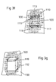
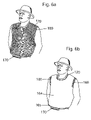
- FIG. 6 a shows a forced air shirt embodiment designed to be used under an existing T-shirt.
- FIG. 6 b shows the device in FIG. 6 a with existing T-shirt in place.
- FIG. 6 c shows an embodiment designed to be worn under an existing baseball cap.
- My personal cooling system combines a unique, flexible heat sink with a method of maximizing the evaporative cooling effect.
- Fan-free embodiments are the simplest; all other expressions start there and provide additional features and benefits.
- Reservoir 100 is preferably made of a nylon/spandex or cotton/spandex fabric. Other materials that can be used include woven or nonwoven fabrics, foamed, porous, or laminated materials, etc. Reservoir 100 preferably provides a linear path for capillary action (vs. random path wicking provided by foamed materials) to effectively wick water vertically. Reservoir 100 not only wicks and holds water, but also provides a flexible backbone for the device.
- Elements 120 are both thermally conductive throughout and fluid-wicking on at least portions of their surfaces. They are preferably formed of rectangles (heat sink radiation fins) of high-purity aluminum (for maximum heat transfer combined with low weight and cost), having dimensions of approximately twenty five thousandths of an inch thick by one quarter of an inch wide by one inch long. Each fin is formed into a square “U” shape, inserted through slits 104 in reservoir 100 , and the two ends are curved toward each other and down toward the inside bottom of the “U”, whereby element 120 mechanically attaches itself to reservoir 100 in the manner of a staple. This approach:
- FIG. 1 a depicts fluid-wicking surface 124 of element 120 with fine, crosshatched lines, each line representing a tiny groove in the surface of the aluminum.
- FIG. 1 b shows a section view of reservoir 100 with four elements 120 .
- Reservoir 100 can be made of any strong, flexible, preferably elastic, rapidly wicking and highly absorbent material such as nylon/spandex or cotton/spandex fabrics. In most embodiments, for the sake of the user's comfort, reservoir 100 is preferably less than one tenth of an inch thick.
- Reservoir 100 can have a continuous outer reservoir barrier 101 on the outside-facing surface to prevent water from evaporating directly from the fabric into the air, rather than from the surfaces of elements 120 , thereby conserving water and prolonging the cooling effect before rewetting.
- outer reservoir barrier 101 can be discontinuous, providing some protection from evaporation while still allowing the user to wet reservoir 100 directly.
- Reservoir 100 can (and, in most cases for comfort should) also have an inner reservoir barrier 102 on skin-facing surface 125 to prevent moisture in reservoir 100 from wetting the user's skin.
- inner reservoir barrier 102 can cover both primary fluid reservoir 100 the skin-facing portions of elements 120 .
- this creates the problem that almost any waterproof barrier, no matter how thin, also tends to act as a thermal insulator, reducing the cooling effect.
- a comfortable, waterproof, elastic barrier can be made by filling inner reservoir barrier 102 with aluminum powder (or other thermally conductive material), thus greatly increasing its thermal conductivity.
- both the inner and outer surfaces of reservoir 100 have a continuous moisture barrier, special means must be provided for the user to wet reservoir 100 . This can include wetting:
- FIG. 2 a shows a headband embodiment prior to being worn.
- a grid of elements 120 penetrate reservoir 100 as previously described, and inner reservoir barrier 102 (not seen in this view) protects the user's skin from being wet.
- Outer reservoir barrier 101 keeps water from evaporating directly into the surrounding air, forcing all of it to migrate onto surfaces 124 before evaporating.
- Hook-and-loop fasteners 131 at each end allow the user to secure the device to his or her forehead.
- Different embodiments can provide different ways to soak reservoir 100 , such as by immersing the device in a basin of fluid, by dousing it with a hose, or by squirting or spraying it with liquid from a container.
- the user can simply immerse the device in a sink and the water will seep into reservoir 100 around the edges of slits 104 and by migrating through elements 120 .
- FIG. 2 b shows a user wearing the device.
- fluid will migrate onto fluid-wicking surfaces 124 of elements 120 by capillary action. Because the fluid is spread in a very thin layer over a relatively large surface area, the surrounding air has easy access to the molecules of water, and readily absorbs it according to the air temperature and humidity. As the evaporating water is carried into the surrounding air, it carries with it heat that was in elements 120 . As elements 120 cool, they absorb heat from the user's skin, thereby cooling the user.
- FIG. 2 c shows the device made as a T-shirt that is simply pulled on over the head.
- Elements 120 are preferably in solid contact with the user's skin to promote the transfer of heat from the skin through the device and into the air.
- the device can be made elastic and also provide an adjustable fastening system.
- a head cooler can be made elastic, and it can also use hook-and-loop fasteners 131 , allowing the user to adjust the tension of the device against the skin.
- FIGS. 2 d - j show some of the many additional embodiments beyond those already described.
- FIG. 2 d shows a user wearing a cooling vest embodiment.
- device edges 105 can be sealed in a number of ways, including:
- FIG. 2 e shows a user wearing an elastic shorts embodiment.
- FIG. 2 f shows a user wearing a neck cooler embodiment.
- FIG. 2 g shows a user wearing embodiments designed to cool the forearms.
- FIG. 2 h shows a footwear embodiment. All of these embodiments are essentially the same with a few changes in the materials used and the ways they are finished; they are simply shaped differently to fit different body parts.
- Embodiments for human users that can be worn as clothing include long and short sleeved shirts or blouses, shorts, pants, jeans, jackets, vests, dresses, skirts, jumpsuits, robes, bathing suits, sleepwear, hosiery, athletic wear, uniforms, and costumes.
- the device can be embodied as virtually any article of clothing.
- Accessory embodiments can include coolers for the head, neck, shoulders, chest, back, upper arms, lower arms, wrists, hands (gloves), upper legs, lower legs, and feet (boots, shoes, and sandals).
- FIG. 2 i shows a fan-free cooling cap that, like the other embodiments discussed, is essentially a flexible or elastic fabric studded with elements 120 .
- FIG. 2 j shows a close-up view of a section of the cap.
- They can be deformed, cast, or extruded as part of elements 120 , or they can be separate pieces that are attached through any useful means (such as welding, soldering, brazing, gluing, or mechanically attaching) so long as they conduct heat from the scalp to elements 120 .
- a full-body jumpsuit embodiment can be created with many detachable parts.
- the collar can be detached; the forearm pieces, upper arm pieces, lower leg pieces, etc., according to the user's need in the moment.
- the suit can even incorporate an elastic hood that detaches from the collar piece or can be pulled off the head.
- outer reservoir barrier 101 shown in FIG. 1 b . Because the cooling effect is undiminished by the type or thickness of outer reservoir barrier 101 , it can be made of any suitable material such as rubber for sandblasting, polyethylene for chemical resistance, etc. If outer reservoir barrier 101 needs to be thicker than about one hundred and fifty thousands of an inch, elements 120 may need to be made longer than usual and thicker than twenty-five thousandths of an inch to maintain sufficient heat transfer through the length of the fins.
- inner reservoir barrier 102 can also be made of a protective material. If triple protection is needed, reservoir 100 can itself be composed of protective material, provided it is both flexible and absorbent as well as preferably elastic. The points of intersection between elements 120 and reservoir 100 must be carefully sealed to prevent hazardous materials, gasses, or radiation from leaking through to the user's skin. In this case, the two-part version of elements 120 discussed later may work better.
- reservoir barriers 101 and/or 102 can, for example, be latex, polyethylene, ethylene-vinyl alcohol, multi-layered film barrier composites, soft polypropylene laminated fabrics, aromatic polyamides, or any of the hundreds of different materials currently used to resist chemicals. If the device is used to protect against chemicals that can react with whatever material comprises elements 120 , the surface of elements 120 can be treated for protection from such chemicals or elements 120 can be made of a material that will not react with the chemicals in question.
- An embodiment providing physical protection for motorcyclists can use leather as outer reservoir barrier 101 , thereby offering physical protection along with effective cooling power.
- An alternative fan-free motorcycle jacket can be created by combining a fan-free shirt embodiment to be worn against the skin with a leather jacket providing vents in the front and the rear. When a biker is on the road, wind will rush into the device through the front vents, evaporate water from the surfaces of elements 120 , and exit through the rear vents.
- Air intake vents can be slits toward the front of the helmet, funneling the moving air directly to the tops of elements 120 . Slits in the rear of the helmet will allow the rushing air to escape, thereby freeing the device of any need for fans or batteries.
- a fan-free or forced-air embodiment in the form of a blanket or sheet would allow users to simultaneously feel cozy and stay cool, without having air moving against their skin, paying for air conditioning, or being irritated by the noise of a large fan or air conditioner.
- FIG. 2 k shows a fan-free cooling blanket embodiment.
- a reservoir 100 in the form of a flexible, absorbent fabric, studded with a grid of elements 120 .
- the skin-facing surface of the blanket is coated with a flexible, waterproof, thermally conductive inner reservoir barrier 102 , not shown in this view.
- Element-free zone 223 is provided because elements need only be closer to the center, where the user's body is likely to be. The user would simply pour a glass of water on the center of the blanket and get cozy. The water will rapidly migrate throughout reservoir 100 , onto the fluid-wicking surfaces 124 of elements 120 , and evaporate into the surrounding air, thereby cooling the user.
- FIG. 2 l shows an embodiment for cooling a dog. Except for its shape and a few other details, it provides essentially the same solution for dogs and animals as the baseball cap in FIG. 2 i provided for humans.
- FIG. 2 l shows the outside of the device as a fabric studded with elements 120 . The inside of the device is exactly like the detail shown in FIG. 2 j , with element extensions 123 protruding from the bottoms of elements 120 , thereby penetrating through the animal's fur and delivering cooling relief directly to the animal's skin.
- Fan-free embodiments can be used for both cooling and warming, according to the needs of the user.
- a user can wear one set of clothes that will maintain thermal comfort day and night, indoors and out.
- a user can put on a fan-free long-sleeved shirt embodiment and a fan-free jeans embodiment and head out into the sun.
- the plurality of cooling elements creates a huge surface area from which moisture can evaporate (thereby removing more heat than is removed through perspiration), the user will actually be cooler under the heavier cooling clothing than if he or she had ventured out with no clothing at all.
- a user steps into an air-conditioned building, he or she need only throw an extremely light outer covering over the shirt and/or jeans, and suddenly not only can the water no longer evaporate, but the thermal insulation provided by reservoir 100 , outer reservoir barrier 101 , inner reservoir barrier 102 , air space 165 , and the thin outer shell will act as a jacket, quickly warming the user.
- An outer layer to be thrown over the device can be sold as an integral part of the system and can also be packed into a tiny bag or be kept in a pouch or pocket that is part of the device. Whether the user throws on an outer shell that is designed to be used with the device, or uses an existing article of clothing, they should block all potential air exits by buttoning the wrists, tucking in a shirt or blouse, etc. to prevent air from circulating around elements 120 , thereby reversing the desired warming effect.
- water or other cooling fluid
- wet reservoir 100 there are many ways to store the water (or other cooling fluid), distribute it, and wet reservoir 100 as well as elements 120 .
- water was stored in primary reservoir 100 , which automatically distributed the moisture by capillary action to elements 120 .
- the user can douse the device in a sink or other body of water, spray it with a hose, or wet it by sparing with a stream or spray of liquid from a bottle.
- FIG. 3 a shows that one or more additional reservoirs 110 can be provided around the device, which the user can fill or soak from an external reservoir 109 (such as a bottle) without overfilling or causing excess water to spill on the user or the floor.
- the illustration shows a user wearing an elastic T-shirt embodiment with long, thin additional reservoirs 110 placed on the shoulders.
- Embodiments using capillary action to distribute water should place at least one additional reservoir 110 at or near the highest point on the device. This is because, although water will migrate uphill through absorbent materials, due to the effects of gravity it does so more slowly than it migrates downhill.
- a long notch 114 Running through the length of additional reservoir 110 is a long notch 114 .
- a piece of wicking material 118 serving as reservoir bottom 222 , such as a piece of tightly woven cloth or a thin piece of porous plastic, which provides a way for water to be channeled to both ends, rather than splash directly onto elements 120 and/or reservoir 100 .
- Material 118 also creates a wicking interface between sponge 112 and the tops of element 120 .
- Attached to the entire top of additional reservoir 110 is a piece of waterproof material (in this case, a clear flexible plastic) functioning as reservoir cover 220 . In the center of reservoir cover 220 is a long oval reservoir opening 221 .
- a user can take an external reservoir 109 such as a water bottle with a pointed top, insert it into the slot exposed by reservoir opening 221 , urge it toward the front end of reservoir opening 221 , and squeeze. Water will flow from external reservoir 109 into notch 114 , and as it runs downhill it will be absorbed by sponge 112 on each side. The user can then slide the tip of the water bottle back until it hits the back end of reservoir opening 221 , and squeeze again to wet the sponge in the back part of additional reservoir 110 .
- an external reservoir 109 such as a water bottle with a pointed top
- FIG. 3 b shows a section view in which reservoir 110 sits on top of elements 120 .
- elements 120 can be kept outside the area where reservoir 110 is located, allowing reservoir 110 to make direct contact with reservoir 100 .
- additional reservoir(s) 110 can be rigid or soft, and can be filled with an absorbent material such as a sponge 112 , or not.
- FIG. 3 c shows additional reservoir 110 with reservoir cover 220 as a soft clear vinyl case over sponge 112 .
- Reservoir opening 221 allows a user to pour water directly into notch 114 in sponge 112 .
- Notch 114 in sponge 112 can be open from the front to the back of additional reservoir 110 , allowing the user to see when the reservoir is filled before it overflows.
- a user can take an external reservoir 109 such as a water bottle, insert its tip into reservoir opening 221 , and squeeze. By peering through clear reservoir cover 220 , a user can see water line 111 as it fills additional reservoir 110 .
- FIG. 3 d shows a top view of reservoir 110 sitting on top of elements 120 .
- FIG. 3 e shows reservoir 110 resting directly on reservoir 100 , with no need for wicking material 118 as an interface
- FIG. 3 f shows additional reservoir 110 as a stiff clear plastic box not filled with a sponge.
- a user can remove reservoir cap 113 and squeeze water into reservoir 110 from a bottle. Holes 117 in reservoir bottom 222 allow water to drip onto wicking material 118 , which transfers the moisture by capillary action to the tops of elements 120 , directly to reservoir 100 , or both.
- holes 117 can be in the back of additional reservoir 110 , with wicking material 118 inserted as a wicking interface between the back of the reservoir 110 and the tops of elements 120 .
- reservoir 110 can be shaped so that holes 117 are in direct contact with reservoir 100 , so that no other wicking material 118 is needed.
- Additional reservoir 110 can be made detachable from the device so instead of squirting water into it, it can instead be submerged in a body of water or placed under a spigot.
- reservoir 110 has a sponge 112 and a cover 220
- the user can open a door, pull out sponge 112 , soak it in water, place it back inside reservoir cover 220 , and close the door.
- FIG. 3 g shows that sponge 112 need not be enclosed in a separate cover, and can be detachably secured by a sponge holder 119 such as wires, straps, or plastic shapes.
- sponge 112 can be protected by a watertight barrier on the outside-facing surfaces to prevent water from evaporating directly from sponge 112 into the surrounding air. As long as the device-touching surface of sponge 112 is exposed, water can migrate from sponge 112 directly onto the tops of elements 120 . If elements were not placed in the sponge area, water can migrate directly from sponge 112 to reservoir 100 .
- each device would have just one or two additional reservoirs 110 .
- Having just one or two reservoirs 110 also provides a minimum number of points from which the water level can be monitored.
- the user can simply look through clear reservoir cover 220 and see if more water is needed.
- sponge 112 can be impregnated with cobalt chloride or any chemical that turns a different color when wet vs. when dry.
- the system can electronically detect when the system is low on water (such as by measuring electrical resistance between two points on the device) and can activate an alarm, blinking light, voice notification, etc., alerting the user to add water.
- the device can incorporate means to manually or automatically spray water stored in additional reservoirs 110 onto elements 120 , but any such approach would likely be far more complex and far less practical than the various capillary distribution means already discussed. If automated means are used, it can include commonly available means to determine when extra water is needed.
- additional reservoir(s) 110 can be watertight bottles from which fluid can drip or flow by gravity through tubes or channels that connect additional reservoir(s) 110 to various parts of the device. If the system depends on gravity to deliver the water (a more complicated and less efficient solution), the user will need to manually turn the water delivery system on and off, or an automatic system will be needed that can sense the dryness of an area and activate valves to start and stop water flow. This configuration would also require additional reservoirs ( 110 ) to have watertight lids, an extra hassle for the user to deal with.
- FIG. 4 a shows a variation on the shape of elements 120 , in this case to add more surface area.
- Elements 120 can have any shape as long as they wick fluid and conduct heat.
- elements 120 are composed of two parts.
- Bottom element part 121 is designed to be in contact with the user's skin, and to interlock with top element part 122 through a hole it punches in reservoir 100 and reservoir barriers 101 and 102 .
- Top element part 122 is designed to snugly interlock with bottom element part 121 , to be fluid wicking, and to conduct heat.
- Top 122 and bottom 121 are designed to permanently mate in the manner of a snap-together fitting. It is important that both parts mate together tightly so heat conducts well between the two parts. This approach allows elements 120 to be secured to reservoir 100 without using glue, while sealing the intersection and preventing moisture in reservoir 100 from wetting the user's skin.
- FIG. 4 c is essentially the same, but has a more rounded top part 122 to make the outside of the device smoother to the touch.
- FIG. 4 d shows how top part 122 can provide extra surface area for evaporation.
- Bottom part 121 can also have extensions 123 when elements 120 are used to cool skin through hair or fur.
- FIG. 4 e depicts a special snap tool 190 that functions like a pair of pliers.
- Tool 190 has lever arms 191 , a pivot point 192 , and jaws 193 .
- a user would place top element part 122 into holder for element top 194 , bottom element part 121 into holder for element bottom 195 , place existing clothing article 194 between open jaws 193 , and squeeze lever arms 191 together until the two element parts penetrate the article and snap together.
- FIGS. 4 f - h show three different ways to make a removable two-part element system that would allow users to manually insert elements 120 without a special tool. All three are based around a central pin-like stud that will penetrate through the fabric of an article of clothing without tearing it.
- FIG. 4 f shows an embodiment that functions in the manner of a snap.
- Bottom element part 121 has a pointed protrusion with a male snap shape 201 .
- Top element part 122 has a female snap shape 202 to receive male snap shape 201 .
- a user simply presses bottom element part 121 through the article of clothing, then presses top element part 122 down into bottom element part 121 until the two parts snap together. To remove them, the user pulls the two parts away from each other.
- FIG. 4 g show a system in which the sharp protrusion from bottom element part 121 is a male threaded stud 203 , and top element part 122 has a female threaded socket 204 to receive it. The user simply presses bottom element part 121 through the article of clothing, then threads top element part 122 onto it.
- FIG. 4 h shows bottom element part 121 as a simple pointed stud with a slightly protruding ridge 208 that keeps top element part 122 from being easily pulled off bottom element part 121 .
- Top element part 122 is much like a binder clip; it has two fluid-wicking fins 205 , a “C” spring 206 , and clip jaws 207 .
- Fluid-wicking fins 205 must either be stuff enough to withstand being squeezed together many times by the user, or must be framed around the edges with a very stiff material.
- “C” spring 206 functions to hold top element part 122 to bottom element part 121 .
- Clip jaws 207 are curved to make solid thermally conducting contact with bottom element part 121 . The user simply presses bottom element part 121 through the article of clothing, then clips top element part 122 onto it.
- top element part 122 and bottom element part 121 must be created to mate closely to maintain maximum thermal conductivity between them.
- Top element part 122 must have wicking surfaces that will make a wicking contact with clothing article 164 when installed. Once the user has installed a plurality of elements into the article of clothing, he or she will put the article on and wet it. Water from the clothing will wick onto the fluid-wicking surfaces of top element parts 122 and evaporate, cooling the user.
- top element part 122 , nor bottom element part 121 , nor a single-piece element 120 can be made too large before it starts detracting from the flexibility and comfort of the device. However, if elements 120 are corrugated, they will themselves become flexible and can therefore be made much larger.
- FIG. 4 i shows how by taking strips of aluminum, making capillary micro-grooves in the surface (not seen in this edge view), and corrugating them in two dimensions (like the inside layer of corrugated cardboard), elements 120 can cover larger areas of the body while remaining flexible.
- the flexibility, however, is limited to one dimension, therefore any device making use of such corrugated strips will need to limit the width of each strip both for the user's comfort as well as for the sake of maintaining maximum contact between skin-facing surface 125 of the device and user's skin 150 .
- FIG. 4 j shows a cooling vest made of such corrugated, fluid-wicking aluminum strips 126 .
- the fluid storage and wicking functions performed by primary fluid reservoir 100 in previous embodiments are now assumed by the flexibility and fluid-wicking ability of 2-D corrugated element strips 126 themselves.
- additional fluid reservoirs 110 (absorbent fabric or fluid-wicking foamy material) are provided. By placing them at the edges of the device, additional fluid reservoirs 110 double as a way to finish the sharp aluminum edges of strips 126 with a soft material that is comfortable to the skin.
- 2-D corrugated element strips 126 are connected via elastic connectors 115 , preferably absorbent elastic fabrics. Fluid-wicking surfaces 124 face the outside, and skin-facing surfaces 125 are placed against the user's skin. When a user wets additional fluid reservoirs 110 , water quickly spreads by capillary action onto the surface of 2-D corrugated element strips 126 and evaporates directly into the surrounding air.
- the reason this improves on natural perspiration is because the corrugations in elements 120 create a surface area greater than the user's skin, thereby making much more water available at the surface for evaporation, which in turn increases the heat pump effect.
- FIG. 4 k shows how by taking thin sheets of surface-wicking aluminum (or other thermally conductive material) and deforming them into an egg-crate pattern, the elements become flexible in three dimensions.
- Fluid-wicking surface 124 faces the outside of the device, and skin-facing surface 125 is placed against user's skin 150 .
- FIG. 4 l shows how, as in FIG. 10 b with 2-D corrugated element strips 126 , the same can be done with even larger pieces of 3-D corrugated elements 127 because they are more flexible and will therefore more easily maintain contact with the shape of the user's skin.
- FIG. 4 m shows how a cooling vest can be made from a single sheet of 3-D corrugated, fluid-wicking, thermally conductive material.
- skin-facing surface 125 of the device can also be created or treated to promote the wicking of water, with means to allow water to migrate from one surface to the other.
- a simple way to accomplish this is to make the device of a thin piece of aluminum with crosshatched grooves that penetrate more than 50% of the thickness on both sides. By making the grooves horizontally on one side, and vertically on the other, small gaps will be formed where the grooves intersect in the center of the thickness, allowing water to migrate from on side to the other.
- This configuration permits the user's own perspiration to add to the moisture being evaporated on the outside surface of the device.
- the drawback is that water added to the outside surface will be wicked onto the user's skin, creating potentially uncomfortable sensations.
- the benefit of using a corrugated or deformed thermally conductive material created or treated to wick water is that it is extremely inexpensive to produce.
- the drawback is that it is far less flexible than the approach of interconnecting smaller elements 120 with a flexible material (such as a spandex fabric) as previously described, and is therefore less comfortable for the user.
- FIG. 4 n shows a perspective view of another variation on means to create device flexibility.
- Elements 120 are similar to the staple-shaped pieces described previously, but have four ends instead of two, and all are bent in and down toward the center as before. This allows them to be connected together in a grid pattern using non-wicking elastic connectors 225 , such as rubber bands, springs, vinyl, etc., giving groups of elements 120 flexibility as a whole.
- FIG. 4 o shows a top view of a group of elements 120 connected together.
- the device can incorporate means to manually or automatically spray water on elements 120 , but any such approach is far more complex and tedious than by supplying water as previously described through a flexible reservoir such as an elastic fabric. Additional reservoirs can be suspended in the blank squares between elements 120 , but that is almost the same as returning to embodiment #1, with elements 120 being supported by reservoir 100 .
- FIG. 4 p shows a method that provides flexibility while also storing and distributing water and letting the user's skin breathe.
- Elements 120 penetrate the edges of elastic wicking fabric 115 (or other elastic wicking material), which stores water and wets both the inside and outside surfaces of elements 120 .
- the square spaces between fabric 115 and elements 120 give the user's skin access to the surrounding air. This approach is essentially the same as was described in Expression #1 embodiments if holes had also been punched through reservoir 100 .
- FIG. 4 g shows another variation in which elastic connectors 125 can be any material that is both fluid-wicking and flexible (preferably elastic), such as foam, elastic fabric, porous rubber, or porous elastomeric plastics.
- the resulting device will have air spaces that allow the user's skin access to the surrounding air so it can breathe. In this approach, water will be forced to migrate from one element to the next through elastic connectors 125 .
- Elements 120 preferably penetrate reservoir 100 and are secured to it by any effective means, including glue, or by virtue of the shape of elements 120 gripping or interlocking with reservoir 100 as discussed above. However, elements 120 do not need to penetrate reservoir 100 ; they can be attached to the edges of holes punched in reservoir 100 . In either case, contact between elements 120 and reservoir 100 must allow fluid from reservoir 100 to migrate directly onto the surface of elements 120 by capillary action.
- Elements 120 can also be made of a foamed thermally conductive material (such as foamed aluminum), which would serve two purposes: 1) to wick fluid up the elements for evaporation, and 2) to transfer heat from the skin to the evaporating fluid.
- foamed aluminum available today is either far too expensive or not porous enough to wick water. In any case, it is anticipated that foamed aluminum or copper would not perform the thermal conductivity function as well as solid aluminum or copper with a micro-grooved surface.
- Treatments to promote water to wick across the surface of elements 120 include but are not limited to:
- Option 1 is inefficient because in general the coating itself acts as a thermal insulator, allowing water to evaporate, but reducing the heat transfer effect.
- Option 2 is technically difficult to produce and is not likely to be useful because anything printable on the surface (even aluminum powder) would need to include binders, which are at least mildly thermally insulating.
- binders which are at least mildly thermally insulating.
- one of many effective capillary powder coatings can be made by adhering 100 mesh silicon carbide grit (commonly used for sandblast etching) to the surface of the aluminum elements using a urethane-based glue.
- Option 4 is not as effective as option 5 because it provides less surface area from which water can evaporate.
- Option 5 is by far the most effective because it does not insert any thermally insulating substances (such as glues, inks, powders, or granules) between the thermally conductive elements and the air.
- thermally insulating substances such as glues, inks, powders, or granules
- the cross-hatched or crisscrossed groove pattern provides for maximum water to migrate onto the surface for evaporation.
- Micro-deformation using finning discs was earlier described as the preferred method of creating surface grooves.
- Such grooves can alternatively be formed by means of engraving, micro-machining, laser cutting, wire EDM (electrical discharge machining), and other methods.
- Grooves or channels can also be created by composing the elements of innumerable layers of extremely thin material, such as alternating widths of thin aluminum. When the layers are fused or adhered, the narrower layers form the bottoms of the capillary channels, while the wider layers form the walls of the channels. Such a process, however, is not likely to be cost effective.
- An alternative way to prevent water from leaking onto the user's skin is to provide fluid-wicking surfaces on elements 120 only on the outside-facing areas of reservoir 100 , but not continuing through to skin-facing surface 125 .
- This approach is not as waterproof as that mentioned just above. It would also be difficult to manufacture elements 120 using finning discs such that the cross-hatched grooves stop short of the skin-touching areas.
- each row of elements 120 can be offset so that slits 104 in reservoir 100 don't line up, since aligning them would effectively create an easy-to-tear perforated line.
- Other approaches can be employed to strengthen the device, such as by reinforcing reservoir 100 with a strong, flexible material at various points within and/or around the edges of the device. If such material also had wicking properties, it can double as an additional reservoir 110 .
- the stiff material for distributing weight were continuous (as in a thin sheet of plastic), it would have the effect of preventing the surrounding air from moving freely around elements 120 , which would mediate the cooling effect. Using a fan to move the air in such areas would turn that area of the device into a forced-air embodiment as described next. If the stiff material for distributing weight were discontinuous (such as with a stiff plastic mesh), it can allow air to continue to circulate around elements 120 without the need for a fan.
- forced-air embodiments provide an ideal solution to the problem of maintaining maximum cooling comfort in hot temperatures.
- Forced air embodiments fall into two categories: 1) embodiments in which an external air barrier to confine airflow to the area surrounding elements 120 is integrated, and 2) embodiments in which an existing article of clothing, accessory, or piece of gear is used as the external air barrier.
- the former is discussed as Expression #2; the later will be discussed later as Expression #3.
- FIG. 5 a illustrates a simple forced air embodiment for cooling the forehead. Comparing this with FIG. 2 a , it can be seen that two things have been added: 1) an air space 165 adjacent and parallel to the user's skin formed by an outer barrier 160 into which elements 120 penetrate, and 2) means to propel air through the space, such as with a fan 170 , batteries 172 , and switch 171 .
- Outer air barrier 160 can be made of any flexible and preferably elastic material that restricts airflow to the region around elements 120 , and can be water-resistant or absorbent. This is the essence of all the forced-air embodiments.
- FIG. 5 a to operate, the user will wet reservoir 100 , place skin-facing surface 125 of the device against the forehead, wrap the ends of the device around the head, then secure the ends together with hook-and-loop fasteners 131 or any other fastener, such as a snap, clip, button, or catch.
- FIG. 5 b shows the device in place on a user's head. The water in reservoir 100 will rapidly migrate by capillary action onto fluid-wicking surfaces 124 of elements 120 . The user will then turn switch 171 to the “on” position, which connects battery 172 with fan 170 .
- Fan 170 pulls air into the device through intake vent 166 , through the length of air space 165 , and out through fan 170 , circulating air around all of elements 120 .
- the water on fluid-wicking surfaces 124 readily evaporates, carrying heat from the user's forehead through elements 120 and out into the surrounding air.
- FIG. 5 c depicts a forced-air embodiment that cools the forehead as well as the scalp around the sides and back of the head.
- a fan 170 is provided, along with a plurality of elements 120 that penetrate reservoir 100 into air space 165 formed by barrier 160 .
- the skin-facing surfaces of elements 120 around the sides and back of the head have the same kind of rounded, rod-like extensions described for the fan-free baseball cap ( FIG. 2 i ) and the dog cooler ( FIG. 2 l ).
- FIG. 5 d shows how cooling element extensions 123 bring cooling relief to the user's scalp 152 by penetrating user's hair 151 .
- barrier 160 is water-wicking, so the user need only wet the outside of the device, pull it on over the head, and turn on fan 170 . Air is drawn in through vents 166 and out through the fan. Edge barrier 161 forces the air to move past all elements 120 .
- FIG. 5 e shows the device embodied as a forced-air cooling vest.
- the principle is the same as depicted in the cooling headbands described above, but here reservoir 100 and elements 120 cover the user's entire torso.
- Additional fluid reservoirs 110 provide centralized locations for the user to insert water, which migrates throughout the device, feeding moisture to elements 120 .
- Additional fluid reservoirs 110 provide an easy way to wet the device.
- Sponge 112 has notch 114 , which increases sponge surface area, allowing it to absorb water as quickly as it is being inserted. A user would insert the tip of a water bottle into reservoir opening 221 and squeeze; the water will move through notch 114 , rapidly wetting sponge 112 , and, through capillary action, will also wet all of reservoir 100 .
- Fans 170 draw air into the device through air intake vents 166 at the edges of the vest and circulate air through air space 165 , speeding evaporative cooling from elements 120 .
- Backpackers have the problem of needing to cool their back, but unless the backpack is held away from their body by a frame or spacer, the fan cannot be located on the back because it would be blocked by the pack.
- a vest such as the one depicted in FIG. 5 e would keep the user cool.
- Such a device can have one or more fans located on the sides, front, top edges, or bottom edges of the device.
- An embodiment for backpackers might need to integrate means to prevent the backpack from putting undue pressure on the elements 120 . This can be accomplished by inserting cushioning material between outer air barrier 160 and the backpack, or by inserting a stiff material that will distribute the weight of the pack across a larger area of elements 120 .
- FIGS. 5 f and 5 g show reservoir 110 from above.
- Reservoir 110 interfaces with elements 120 either by sitting on top of elements 120 as in FIG. 5 f , or by sitting directly on reservoir 100 as in FIG. 5 g . If reservoir 110 is sitting on the tops of elements 120 , wicking material 118 is used to contain water as it is being poured into reservoir 110 through notch 114 , while also distributing it across the tops of elements 120 .
- outer air barrier 160 itself can fulfill the function of additional fluid reservoir 110 simply by making it of a wicking material.
- a wicking material can also be coated with a waterproof material either to prevent water from evaporating directly in the surrounding air or to prevent the outside of the device from wicking water onto anything the user may be leaning against.
- FIG. 5 h shows the device embodied as a forced-air baseball cap. Comparing this with FIG. 2 i , what has been added is barrier 160 forming an air space over elements 120 , and a fan with batteries and a switch. Fan 170 is placed in the ideal location at the top center of the hat, where it can draw air equally from all intake vents 166 . The user wets the cap, puts it on, and turns on the fan. Cooling element extensions 123 on the bottoms of elements 120 (not shown) penetrate through the hair and touch the scalp, cooling the user's head. Additional reservoir 110 can be provided in the form of the visor, which can be made of a slightly stiff, but rapidly wicking material, such as a porous plastic, or felt with a stiff backing.
- FIG. 5 i shows a forced air blanket embodiment.
- Fan 170 can be run using either battery 172 or power from a wall outlet. The user would add water to additional reservoirs 110 , turn on fan 170 , and enjoy cooling comfort all night. If needed, a very thin piece of soft fabric can be provided to keep skin-facing surface 125 of the blanket (not shown) from touching the user's skin, making it feel cozier to the user.
- a forced-air pet cooler very similar to the version depicted in FIG. 2 l can be created by adding an air space 165 adjacent and parallel to the animal's fur (created by outer air barrier 160 ), one or more fans 170 to propel air through space 165 , and elements extensions 123 .
- outer air barrier 160 is made of whatever material is necessary to protect the user from physical, thermal, chemical, biological, or radioactive hazards. If double or triple protection is needed, outer reservoir barrier 101 and/or inner reservoir barrier 102 can also be made of whatever protective material is needed. If quadruple protection is needed, reservoir 100 can itself be made of any flexible and absorbent protective material, which is preferably also elastic.
- the device may need to keep external air from touching the skin of the user.
- the entire air stream as it enters the device, travels around elements 120 , and exits the device, must be isolated from the user's skin as well as the air the user is breathing.
- FIG. 5 j shows an integrated forced-air embodiment providing physical protection for bikers.
- This device uses leather as outer air barrier 160 , which forms motorcycle jacket shell 184 .
- Fan 170 is located in the middle of the back, and air intake vents 166 are located near all edges of the device.
- Beneath motorcycle jacket shell 184 is an inner layer like that depicted in FIG. 2 c , with reservoir 100 studded with elem 120 .
- This inner layer can be attached, not attached, or detachable from jacket shell 184 . The user wets the inner layer, puts the device on, turns on fan 170 , and enjoys cooling relief whether in motion or not.
- FIG. 5 j depicts a forced-air hard hat embodiment. It is essentially the same as the forced air baseball cap in FIG. 4 h except that the outer air barrier is replaced with the stiff shell of hard hat 181 .
- the device has an inner cap studded with elements 120 having extensions 123 .
- suspension straps 180 are added, which function exactly as they do in normal hard hats, creating a safety zone around the user's head.
- Suspension straps 180 can be an integral part of the inner cap, and elements 120 can be penetrate through suspension straps 180 as well as the inner cap that is acting as reservoir 100 .
- suspension straps are attached to the outer shell of hat 181 at intervals.
- the user wets reservoir 100 , puts on the device, and turns it on.
- fan 170 activates, it draws air in around the edges of the device (functioning as intake vents 166 ), over elements 120 , and out through the fan, cooling the user.
- FIG. 5 k shows a motorcycle helmet embodiment.
- Helmet 182 has a thick layer of foam padding 183 inside, which can double as additional fluid reservoir 110 .
- Water can be added from the bottom side of elements 120 (with cooling element extensions 123 now shown) or through one or more holes in the top of helmet 182 .
- foam padding 183 As water soaks through foam padding 183 , it migrates onto and across fluid-wicking surfaces 124 of elements 120 , and into primary fluid reservoir 100 .
- fan 170 air is drawn in through air intake vents 166 , across elements 120 , and out through fan 170 , cooling the user's head.
- elements 120 are attached directly to foam padding 183 , eliminating the need for reservoir 100 as a means to support elements 120 .
- foam padding 183 itself acts as the primary fluid reservoir and, because of its thickness, can hold a tremendous amount of water.
- FIG. 5 m depicts a thermostat-controlled jacket.
- Thermostat 140 is connected to a temperature sensor 141 on the inside of the device, a control circuit 142 , and fan 170 (not shown; in the center of the back).
- control circuit 142 will respond as follows:
- control circuit 142 can also trigger the blocking of all open edges of the device with controllable edge air barriers 162 to speed the internal warming of the device.
- Controllable edge air barriers 162 can be opened or closed by any suitable means, such as by inflating plastic “balloons” along the edges, thereby sealing the air vents, or by using mini servo-motors, linear actuators, or nitinol-type wires (or other material that expands or contracts with the application of an electrical charge) to mechanically slide or close flaps.
- the edges might also be blocked without the use of a control circuit by using vents with very lightweight flaps that stay open only when a fan or other air-moving device is forcing air through them.
- Thermostat 140 can be used as a mechanical switch for fan(s) 170 in the same manner that analog thermostats control home furnaces. But an advantage of having a control circuit is that it can sense the rate of change of the user's skin temperature and adjust the speed of fan(s) 170 accordingly, thereby creating a stable thermal environment that does not subject the user to rapid changes in temperature that would result if the device is either on or off. This will be a great boon to users who are extremely sensitive to sudden or even slight temperature changes.
- a warming/cooling jacket can be made with a number of automatically-controlled zones that respond to the different thermal needs of different parts of the body.
- Such a device need not add extra reservoirs 110 because water can migrate into different thermal zones without interrupting internal air barriers 163 . This approach will be useful for anyone whose body tends to get colder is some areas more easily than others.
- Barriers 162 can be closed manually by blocking the air intake and exhaust areas. This can be accomplished by tightening a drawstring, closing a flap, zipping two flaps together, clipping one part to another, etc.
- Options that can be activated either manually or automatically include pivoted flaps, sliding flaps, rotating vents, interconnecting cells with parallelogram shapes that stand up or collapse as a unit, and inflatable “balloons”, etc.
- outer air barrier 160 were itself a thermal insulator (such as down, wool, fleece, fur, synthetic insulation, etc.), the range of temperatures that a warming/cooling jacket (or any other embodiment) can accommodate is greatly increased.
- a warming/cooling jacket or any other embodiment
- an insulated version of outer air barrier 160 would keep hot air and sunlight from mediating the cooling effect of the device, thereby increasing its efficiency.
- an insulated version of outer air barrier 160 would more efficiently retain the user's body warmth.
- Such a warming/cooling jacket can automatically keep a user comfortable year-round in either hot or cold weather.
- FIG. 5 o shows an edge view of a section in which bottoms of elements 120 are touching the skin as before, but the next layer in the system is stabilizing fabric 103 instead of reservoir 100 .
- Stabilizing fabric 103 can be any fabric that is flexible (and preferably elastic), and has the primary function of holding elements 120 stable relative to each other. In the configuration shown, this function is very important, because if reservoir 100 were not highly elastic, when the device is curved around a body part, the skin-facing portions of elements 120 would be forced closer together, and can potentially pinch the user's skin if stabilizing fabric 103 wasn't there to hold them apart.
- FIG. 5 p shows that a simple way to mediate the pinching effect is to make the skin-touching parts of elements 120 curved and not use fabric 103 .
- Stabilizing fabric 103 can be an open mesh and can also be partially or completely closed or watertight. If it is an open mesh, or, as in FIG. 5 p , fabric 103 is not used, when fan 170 is on and air is moving through air space 165 , air will move between the heads of elements 120 and speed the evaporation of any perspiration on the user's skin, which might be an advantage in some applications.
- the combination of outer reservoir barrier 101 , reservoir 100 , and inner reservoir barrier 102 will perform the function fulfilled by outer air barrier 160 as show in previous Expression #2 embodiments; it will define the top of air space 165 , confining the forced air to the spaces between elements 120 .
- This configuration also has the advantage of making it easier to wet reservoir 100 because it is closer to the outside of the device. For example, additional reservoirs 110 can be attached directly to the surface of reservoir 100 in a number of locations.
- FIG. 5 q shows another option in which reservoir 100 is used both at the tops and the bottoms of elements 120 .
- reservoir 100 is used both at the tops and the bottoms of elements 120 .
- only one of the two reservoirs would need to be wet by the user because water from one would wet the other by migrating through elements 120 .
- Migration can be speeded by providing one or more wicking materials as bridges between the two layers. Such bridges would have to be intermittent so as not to block air from moving through air space 165 .
- outer air barrier 160 restricts airflow to the space surrounding elements 120 is good for maximizing cooling, but also good for trapping moisture inside the device when not in use. For this reason, reservoir 100 , outer air barrier 160 , and any other layers of the device (including inner reservoir barrier 102 or outer reservoir barrier 101 ) can be impregnated with a chemical that will suppress the formation or mold or mildew. Additionally, the user can be instructed to remove outer air barrier 160 and/or keep fan 170 on until the device has thoroughly dried before putting it away.
- Fan 170 can draw air in from the outside and push it through the device and out the edges, or it can draw air into the device from the edges and out through the fan. However, if the fan is pushing air into the device, it will tend to cause outer air barrier 160 to billow away from elements 120 , which might look unappealing. For this reason, configuring the fan(s) to pull air through the device and out through the air is considered a superior solution.
- outer air barrier 160 or any pre-existing outer garment worn over an embodiment designed to accommodate existing garments as described under Expression #3 from billowing away from the device, including the following:
- FIG. 5 a shows permanent edge air barriers 161 on both long edges of the device, forcing the air to move all the way through both ends of the device for maximum cooling.
- Outer air barrier 160 not only bounds the space around elements 120 to restrict airflow, but visually hides elements 120 , providing the possibility of virtually unlimited fashion options. Outer air barrier 160 can be made replaceable, allowing users to buy one base unit and as many outer coverings as suits their needs and desires.
- Forced air embodiments can be created for any body part using corrugated elements 126 or deformed elements 127 described under Expression #1 simply by adding at least an outer air barrier 160 and a fan 170 or other means to move air through the resulting spaces.
- Expression #3 of my cooling system comprises a group of embodiments in which the function of outer air barrier 160 is fulfilled by an existing article of clothing or piece of gear.
- FIG. 6 a shows a device designed to be worn under an existing T-shirt. It is very similar to the fan-free embodiment shown in FIG. 2 c , except also provided is fan 170 , as well as a battery and a switch, not shown. Missing is integrated external air barrier 160 provided with all Expression #2 embodiments.
- the user puts the device on, wets reservoir 100 (thereby wetting elements 120 ), then puts on existing T-shirt 164 and turns on fan 170 .
- Fan 170 draws air in through intake vents 166 , through air spaces 165 formed between reservoir 100 and existing T-shirt 164 , and out through the fan.
- tiny dots or areas of waterproof plastic can be applied to the tops of elements 120 .
- FIG. 6 c shows an embodiment designed to be used with an existing hat or cap.
- Fan 170 is on the edge of the device so it won't be blocked by the user's headwear.
- the user wets reservoir 100 , puts on the device, then puts his or her own existing hat or cap 168 over it.
- fan 170 is activated and begins to circulate air around elements 120 , promoting evaporative cooling. Cooling element extensions 123 on the bottoms of elements 120 are not shown.
- Embodiments can be created to work with existing articles of protective gear.
- an existing chemically resistant suit can perform the function of outer air barrier 160 by slipping it over an embodiment of the device designed to provide proper air circulation for that specific suit.
- a device can be made to accommodate a biker's existing leather jacket. Such a device should not place a fan in any location that would be blocked by the jacket; one or more fans would have to be located at the bottom or top edges of the device, and possibly also at the ends of both sleeves.
- my flexible evaporative cooling system clearly improves on prior-art personal cooling systems while simultaneously making possible a whole new range of personal thermal comfort devices. It delivers a powerful, long-lasting cooling effect directly to the skin of a human or animal user, without requiring the user to hold the device or expend any effort. It does not need to wet the user's clothing or skin. It requires little or no battery power to run (none in the fan-free embodiments). It is flexible, and can therefore be worn comfortably on or against a user's body. It can be easily adapted for use on pets and other animals. It can be embodied as clothing, accessories, uniforms, and protective garments.
- It can be worn under a backpack, motorcycle leathers, or under other garments, uniforms, or protective gear, and it can be used as a sheet, blanket, scarf, or shawl. It can even be embodied as a variety of automated, thermostat-controlled, personal warming/cooling devices.
- Reservoir 100 can:
- Reservoir barriers 101 and 102 can:
- External reservoir 109 can:
- Additional reservoir(s) 110 can:
- Elements 120 can:
- Fluid-wicking surfaces 124 of elements 120 can:
- Temperature control system (thermostat 140 , temperature sensor 141 , and control circuit 142 ) and other electronics can:
- Outer air barrier 160 can:
- Air space 165 can:
- Fan(s) 170 or other air-moving means can:
- Power for electronics and/or air-moving means can be provided by any means, including:
- Low water detection and alert systems can include:
- the cooling fluid can be varied as follows:
- Devices can vary in size, shape, color, and design, and still fall within the intended scope of the invention.
- the major elements can be put in different positions than shown (e.g., batteries can be located where a water reservoir is depicted, etc.).
- the scope of the invention should be determined by the descriptions given above, along with the appended claims and their legal equivalents, rather than by the examples given alone.
Landscapes
- Engineering & Computer Science (AREA)
- Health & Medical Sciences (AREA)
- General Health & Medical Sciences (AREA)
- Public Health (AREA)
- Epidemiology (AREA)
- Biomedical Technology (AREA)
- Veterinary Medicine (AREA)
- Vascular Medicine (AREA)
- Life Sciences & Earth Sciences (AREA)
- Animal Behavior & Ethology (AREA)
- Thermal Sciences (AREA)
- Physics & Mathematics (AREA)
- Heart & Thoracic Surgery (AREA)
- Microelectronics & Electronic Packaging (AREA)
- Chemical & Material Sciences (AREA)
- Materials Engineering (AREA)
- Environmental & Geological Engineering (AREA)
- Physical Education & Sports Medicine (AREA)
- Textile Engineering (AREA)
- Professional, Industrial, Or Sporting Protective Garments (AREA)
Abstract
Description
-
- The user must hold a device or take some action to derive a benefit (which is not only bothersome but may be tiring and self defeating, since such activity can generate more internal heat than it dissipates).
- Removing clothing is often inappropriate or undesirable.
- Changing into lighter clothing is often inconvenient or inappropriate.
- Wetting the body and/or clothing can be uncomfortable, unaesthetic, or even embarrassing.
- They provide only short-term relief.
- They provide relatively ineffective cooling.
- They are impossible or impractical to implement when wearing heavy or protective clothing or equipment.
- They do not cover as large an area as needed.
-
- Pumping cool gels or fluids through a vest or other garment
- Creating portable refrigerators with chlorofluorocarbon coolants
- Transferring coolness from a refrigerator or freezer to the body through liquids, gels, or solid materials
- Using compressed gas to create a stream of cool air or vapor across the skin
- Employing Peltier (thermoelectric) cells
-
- 1. Is smooth and flexible, therefore comfortable when worn against a user's body.
- 2. Can be made and sold inexpensively.
- 3. Is lightweight and unobtrusive.
- 4. Delivers a powerful evaporative cooling effect directly to the user's skin.
- 5. Offers long-term cooling relief.
- 6. Does not require the user to hold the device.
- 7. Requires the user to do little or nothing to enjoy its benefits.
- 8. Does not need to wet the user's skin or clothing.
- 9. Requires little or no battery power to run.
- 10. Would be useful for those who are relatively inactive, as well as those engaged in walking, jogging, or active sports.
- 11. Can cool pets and other animals.
- 12. Can itself be made into and worn as clothing, uniforms, or protective garments.
- 13. Can be worn under a backpack, uniforms, motorcycle leathers or other heavy garments, helmets, protective gear, or ordinary clothes.
- 14. Can be embodied as clothing, accessories, or blankets.
- 15. Can be embodied as devices with adjustable warming/cooling potential.
- 16. Does not require the user to change clothing or add outerwear or accessories as the temperature cools off.
- 17. Can be automatically controlled with a thermostat to maintain a relatively constant skin temperature.
-
- A plurality of thermally conductive elements, each promoting fluid to wick across at least portions of its surface,
- A flexible hydrophilic fabric or sponge reservoir,
- Means for the conductive elements to be maintained in contact with the reservoir so that fluid will tend to migrate from the fabric onto and across element surfaces, and
- Means for maintaining one or more portions of the elements in physical or at least thermal contact with the user's skin,
whereby when the fabric is wet, water has migrated onto the elements, and one or more portions of the elements are in contact with the user's skin, heat from the user's skin is transferred through the elements to the evaporating fluid and into the surrounding air, cooling the user. By adding an air space adjacent and parallel to the user's skin into which the elements penetrate, along with means to move air through the air space, the device is made more powerful. By adding thermostatic control means, the device can be embodied as automatic temperature-regulating clothing.
| 100 | |
||
| 101 | |
||
| 102 | |
||
| 103 | stabilizing |
||
| 104 | |
||
| 105 | device edges | ||
| 109 | |
||
| 110 | |
||
| 111 | |
||
| 112 | |
||
| 113 | |
||
| 114 | |
||
| 115 | |
||
| 116 | |
||
| 117 | |
||
| 118 | |
||
| 119 | |
||
| 120 | |
||
| 121 | |
||
| 122 | |
||
| 123 | |
||
| 124 | fluid- |
||
| 125 | skin-facing |
||
| 126 | 2-D corrugated element strips | ||
| 127 | 3-D |
||
| 131 | hook-and- |
||
| 140 | |
||
| 141 | |
||
| 142 | |
||
| 150 | user's |
||
| 151 | user's |
||
| 152 | user's |
||
| 160 | |
||
| 161 | permanent |
||
| 162 | controllable |
||
| 163 | internal air barrier | ||
| 164 | existing |
||
| 165 | |
||
| 166 | air intake vents | ||
| 167 | existing T- |
||
| 168 | existing |
||
| 170 | |
||
| 171 | |
||
| 172 | |
||
| 180 | |
||
| 181 | |
||
| 182 | |
||
| 183 | |
||
| 184 | motorcycle jacket shell | ||
| 190 | |
||
| 191 | |
||
| 192 | |
||
| 193 | |
||
| 194 | holder for element top | ||
| 195 | holder for |
||
| 201 | |
||
| 202 | |
||
| 203 | male threaded |
||
| 204 | female threaded |
||
| 205 | fluid-wicking |
||
| 206 | “C” |
||
| 207 | |
||
| 208 | protruding |
||
| 220 | |
||
| 221 | reservoir opening | ||
| 222 | |
||
| 223 | element- |
||
| 225 | elastic connectors | ||
-
- 1. Fan-free embodiments: Devices that rely on passive evaporation.
- 2. Integrated forced air embodiments: Devices that use one or more fans to speed evaporation and provide an integrated external air barrier to contain airflow.
- 3. Forced air embodiments for use with existing articles: Devices that use one or more fans and use an existing accessory or article of clothing as the external air barrier.
-
- 1. Thermally
conductive elements 120 with fluid-wickingsurfaces 124, - 2. A way to flexibly interconnect the elements, such as with a flexible fabric
primary reservoir 100, - 3. A way to
wet elements 120, and - 4. A way to maintain at least portions of the elements in contact with a user's skin.
- 1. Thermally
-
- Allows the fins to have sufficient length while taking little vertical space.
- Provides a large skin-facing
surface 125 for cooling the user's skin. - Allows each fin end to be supplied with fluid by wicking action from both locations where it touches reservoir 100 (at
slits 104 and at both ends), effectively creating four fins from one piece. -
Permits elements 120 to be densely packed for maximum cooling effect. - Attaches
elements 120 to the fabric, thereby avoiding the need to use glue in the manufacturing process. - Provides a softer look and feel on the outside of the device than if the fins ended either straight up or were bent down at an angle.
-
- From the edges
- Through
elements 120 - Through fluid delivery means that penetrate at least one reservoir barrier
- By making at least portions of
reservoir barriers
-
- By sewing or gluing a strip of waterproof material around the edges
- By dipping the edges in a waterproofing liquid, plastic, or sealer
- By rolling the edges into a seam that is sewn or heat sealed
-
- Not wish to get themselves wet in order to wet the device,
- Not wish to remove the device in order to wet it,
- Not wish or have the option to jump in a shower, tub, lake or other body of water to wet the device,
- Not have or wish to use a spray bottle to wet the device,
- Have difficulty wetting parts of the device that can't been seen or reached,
- Be unable to determine which parts of the device need water,
- Put too much water on part of the device, resulting in it dripping off and potentially wetting their other clothes or shoes, or spilling on the floor.
-
- 1. Coating with powder, fibers, foam, or other water-absorbent material.
- 2. Printing a pattern of dots on the surface, thereby creating spaces between the dots for the water to wick by capillary action.
- 3. Powder-coating with a granular material, thereby creating spaces for the water to wick between the granules by capillary action.
- 4. Creating tiny parallel, linear grooves in the surface.
- 5. Creating tiny parallel or non-parallel cross-hatched or crisscrossed grooves in the surface
-
- Not placing
elements 120 in such areas. - Insuring that
elements 120 to be used in such areas have shapes that will neither cause damage to external objects nor discomfort when pressed against the user's skin. - Covering
elements 120 in such areas with a material stiff enough to distribute the pressure of contact over a large area ofelements 120.
- Not placing
-
- The user is active (thereby creating a breeze to speed evaporation).
- Less consistent or less forceful cooling is acceptable.
- The use of fans and batteries are undesirable or unacceptable.
-
- If the user's skin is currently at a temperature above that set on the thermostat,
control circuit 142 will turn on fan(s) 170, cooling the user's skin. - If the user's skin is currently at a temperature below that set on the thermostat,
control circuit 142 will turn off fan(s) 170, stopping the cooling action, and, by making use of the thermal insulating effect of all the materials in the device along withair space 165, will warm the user's skin.
- If the user's skin is currently at a temperature above that set on the thermostat,
-
- It would create
extra air spaces 165 that would require ventilation - Drag and turbulence from the extra surfaces would increase resistance to airflow
- The device would be rendered more expensive and less effective.
- It would create
-
-
Outer air barrier 160 can be attached to the peaks ofelements 120, either permanently or removably (such as with a permanently tacky surface glue). - Fan(s) 170 need not be so strong as to billow
outer air barrier 160. - A number of slow-moving
fans 170 can be employed around the device to keep the air moving without causing undue billowing ofouter air barrier 160.
-
-
- Allow users to wear heavier clothing than they would otherwise be forced to wear in hot weather, while remaining cooler than if they had worn nothing at all.
- Provide cooling relief for people engaged in minimal activity such as working in an office or driving, as well as people engaged in walking, running, jogging, hiking, basketball, baseball, summer sports, golf, traveling, sight-seeing, etc.
- Open a whole new range of weather-independent fashion options for users.
- Give people more control over their personal comfort all year round, in hot or cold temperatures, inside and out.
- Reduce reliance on air conditioners.
- Allow users to work and play longer in hot temperatures than they would otherwise be able to tolerate.
- Allow users to live in hotter climates than they could previously tolerate.
- Allow people to own fewer clothes, if they so desire.
- Permit travelers to bring fewer clothes on trips, if they wish.
- Provide cooling relief for sufferers of first-degree burns, such as sunburns.
- Provide means by which sunburn victims can simultaneously cool the burned portions of their skin and warm the unburned portions (using
multi-zone Expression # 2 devices). - Provide protection from mosquitoes and other insect pests. According to the World Health Organization, there are at least 50 million annual cases of insect-borne diseases, many of which are fatal.
- Protect users from overexposure to solar UV radiation while remaining cool and comfortable. Approximately 130,000 malignant melanomas and 66,000 deaths occur globally each year, substantially contributing to mortality rates in fair-skinned populations.
- Provide significant thermal comfort while helping thousands of people survive in extremely hot weather. Every year, tens of thousands of people worldwide die from heat waves. In the summer of 2003, heat waves in Europe killed more than 19,000 people and uncounted thousands of animals. Estimates of the future effects of global warming consistently point to increasing extremes, with even more devastating heat waves.
-
- Be made of anything flexible and absorbent (and preferably elastic), such as:
- A single layer of flexible, absorbent material (made porous with woven or nonwoven fibers, hydrophilic pores, tiny grooves, or pits).
- Two or more layers of different absorbent materials.
- Trapped layers of absorbent beads.
- Be thin, but the thinner it is, the less fluid it will hold.
- Be any shape, so long as it maintains wicking contact with
elements 120. - Have holes at intervals to allow the user's skin to breathe more readily.
- Have antimicrobial and/or antibacterial properties to prevent the formation of mold, mildew, or other undesirable organisms.
- Be impregnated with additives of any kind, including salts, surfactants, oils, and/or fragrances.
- Contain include a number of horizontal moisture boundaries to counteract the effects of gravity, preventing most of the fluid from settling toward the bottom of the device. In this approach, once water is introduced into the material, it can only migrate to the nearest moisture boundary, preventing a wide gradient of saturations and insuring that moisture is available to
elements 120 that are closer to the top of the device. - Be positioned anywhere in the device, as long as it imparts fluid to
elements 120. - Be in more than one piece, but if so, means must be provided whereby all pieces can be moistened. Multiple pieces can be connected in any suitable manner (such as being sewn, pressed, glued, or flame-laminated, or connected by wicks, capillary tubes or channels) so that water migrates between them. Separate pieces of
reservoir 100 can be wet through separate reservoirs or fluid collection and distribution channels. Alternatively, separate pieces can be wet by spraying or dunking the entire device in water.
- Be made of anything flexible and absorbent (and preferably elastic), such as:
-
- Be made of any material suitable to meet the needs at hand. For example, if it is being used to:
-
Seal reservoir 100 from allowing moisture from evaporating from within the device, it should be watertight; -
Protect reservoir 100 from being abraded by use, it should have abrasion-resistant properties; -
Protect reservoir 100 from UV radiation, it should have UV-blocking properties; - Create a fashion statement, it should be easy to print, stitch, or flock a design on it;
- Create a feeling of softness to the user's skin, it should have a soft skin-facing
surface 125; - Help wick perspiration from the user's skin to
reservoir 100, it should be highly absorbent.
-
- Be adhered to
fluid reservoir 100, can be pressed againstreservoir 100 without being adhered, or can be added toreservoir 100 as a coating. - Be omitted entirely and the device will still work. Without one or both barriers:
- Water might leak onto the user's skin or clothing;
- Water will evaporate directly off the surface of
reservoir 100, reducing the effectiveness of the device; -
Reservoir 100 might become abraded by normal wear
- Be made of any material suitable to meet the needs at hand. For example, if it is being used to:
-
- Be provided as an integral part of the cooling system or not;
- Be made attachable and detachable from the device;
- Have a pointed applicator tip that engages with opening 221 in
additional reservoir 110 so that it forces open a part ofreservoir 110, allowingreservoir 110 to function without a cap; - Be any size, shape, color, or number.
-
- Be made of anything that holds and/or absorbs water;
- Be hard or soft;
- Be clear, translucent, or opaque;
- Have walls composed of any watertight (or fluid-resistant) material or not;
- Be filled or not with absorbent material, such as a sponge;
- Be itself a sponge;
- Have an openable or removable cap to prevent water from spilling;
- Be any number, shape, color, or size;
- Be located anywhere on the device;
- Be removable from the device for easy wetting;
- Be located off the device (in the form of a purse, shoulder bag, knapsack, fannypack, etc.), but connected with
reservoir 100 by fluid delivery means such as a wick; - Be simply a pattern of thicker areas on
reservoir 100 or a pattern of one or more different materials attached to or as extensions ofreservoir 100. In either case, such raised areas may not necessarily need means for the user to wet them directly; they can get wet through contact with other wet areas; - Be located at the bottom edge of a shirt or jacket embodiment and can take the shape of a belt;
- Be located at the top edge of a shirt or jacket embodiment and can take the shape of a collar;
- Not only look like a belt, but perform the function of a belt. The belt would preferably not need to be threaded through loops and can be attached with any kind of fastener.
-
- Be made of any thermally conductive material. If metal, it can be any alloy or laminated combinations of alloys and it can be plated or coated with any other material or process that does not prevent the microgrooves or other wicking interstices from wicking fluid in the areas where wicking is needed (on skin-facing
surface 125, wicking may not be desirable). If aluminum, it can be anodized to protect the surface from salts, or plated with, say, nickel, to protect the user from absorbing too much aluminum through skin contact. - Be any number, size, shape, or color, provided they conduct heat, wick water on at least portions of their surface, and allow the device to be flexible.
- Be composed of mixed shapes, sizes, and colors, within any device.
- Be connected to each other by any flexible means, including:
- Being attached to a flexible material that might or might not be absorbent and/or continuous.
- Being attached with any flexible material, such as rubber, vinyl, fabric, sponge, etc. that might or might not be absorbent or wicking.
- Using a portion or extension of the material or materials that comprise
elements 120 that is itself used to make connections with other elements. - Using a flexible connector, such as a spring or hinge.
- Themselves be flexible.
- Be arranged in any pattern whatever.
- Be arranged in any density, and density can be varied according to the needs of different body parts. The farther apart they are spaced, however, the less cooling they will provide.
- Emerge from
reservoir 100 at an angle, allowing the fins to retain length for cooling power, while taking minimal vertical space. - Be oriented in any direction, but should be positioned so as to promote maximum airflow across the fins.
- Be quite short, keeping the cross-sectional profile of the device to well under a quarter of an inch (in some cases, approx. one eighth of an inch). Although restricting the length of the fins would reduce the heat pump effect, the trade-off in favor of less bulk would be attractive to many users. Better yet, the fins can be longer, and formed into a shape that takes little vertical space.
- Be made of two or more parts that connect. Care must be taken to ensure that such parts tightly mate so that heat can move efficiently between them.
- Have one or more downward, skin-facing extensions designed to get through human hair or animal fur to deliver cooling relief to the user's skin.
- Be coated or flocked on skin-facing
surface 125 with any material to change its feel to the user's skin, to prevent fluid from leaking or wicking onto the user's skin, and/or to make skin-facingsurface 125 of the device washable, as long as the coating or flocking does not significantly thermally insulateelements 120 from the user's skin. To reduce the thermally insulating effect of such a coating, it can be filled with a thermally conductive powder, such as aluminum.
- Be made of any thermally conductive material. If metal, it can be any alloy or laminated combinations of alloys and it can be plated or coated with any other material or process that does not prevent the microgrooves or other wicking interstices from wicking fluid in the areas where wicking is needed (on skin-facing
-
- Cover all or part of
elements 120, including any surfaces. - Touch the user's skin or not. If a wicking surface is in contact with the user's skin it will wick up the salty water of the user's perspiration and combine it with the fresh water in the reservoir, eventually leaving deposits of salt on the surface of
elements 120. Theoretically, this may not be a problem; the user can simply douse or spray the device with warm water to dissolve the salt. In practice, if aluminum is used forelements 120, its surfaces may be corroded by the salts, which can negatively affect device performance. To avoid this issue, the portions ofelements 120 that are in contact with the user's skin can be left untreated so they will not wick water. Touchouter air barrier 160 or not. To prevent wetting of outer air barrier 160 (especially if an existing garment is fulfilling the function of outer air barrier 160), those portions ofelements 120 that are in contact withouter air barrier 160 can be left untreated so they will not wick water.
- Cover all or part of
-
- Be analog and/or digital.
- Have built-in intelligence that considers skin temperature, outside temperature, and humidity, keeps records of the user's past thermal preferences, and can thereby control skin temperatures in ways that anticipate the user's needs. GPS data can also be integrated so the system is able to check local weather conditions and/or know if the user is inside a building.
- Control each fan in the device separately or all together.
- Control each of the controllable
edge air barriers 162 separately or all together. - Include a “power on” indicator, such as an LED.
- Include a “low battery” or battery charge status indicator.
- Include a two-color LED to indicate “power on” with one color and “low battery” with the other color.
- Communicate electronic information (such as “low water” status) with the user via any suitable means, including lights, sounds, vibration, visual displays, or voice.
- Include a low-medium-high or variable power switch for varying the fan speed according to the user's needs.
- Provide one or more digital or analog thermometers, enabling the user to monitor air and/or skin temperatures at one or more locations or zones around the device.
- Be made removable, allowing the user to launder the device.
- Be placed anywhere on or off the device. If off the device, it can communicate with the device by wire or wirelessly.
- Use wireless communications between sensors and control circuits to avoid complications in wiring.
- Use wireless communications between itself and a user's devices.
-
- Be made of two or more layers of any suitable materials.
- Be made, at least in part, of an absorbent material, adding extra water reservoir capacity as well as extra thermal insulation. For example, it can have an absorbent inner-facing layer and an impervious outer-facing layer.
- Be made of a transparent material to show off the inner workings of the device.
- Be affixed to the tops of
elements 120 either permanently or temporarily, or can rest against the tops ofelements 120 so that it can shift laterally as needed. - Be made removable and replaceable with different outer shells.
- Avoid touching the tops of
elements 120; means can be used to separate it fromelements 120 so that air can flow over the tops ofelements 165.
-
- Be any height practical, but more than one quarter of an inch is probably not needed, except in unusual cases.
- Be not perfectly uniform in height, but must allow forced air to move freely around
elements 120.
-
- Be any number within a device.
- Be in any location on the device.
- Be in any position relative to
outer air barrier 160. If it is under air barrier 160 (inside of air space 165), it can be arranged to pull air from one side and push air toward the other, causing air to move through the device. It need not intake or exhaust air directly to the outside. - Be made waterproof and/or detachable to protect from being wet when the user adds water or washes the device.
- Be replaced by any type of fan or blower impellers, including radial, axial, and tangential, and different types can be combined within a device.
- Be replaced by any air moving means, including electrostatic or piezoelectric, although to date such means are not sufficiently powerful or efficient for use in a battery-operated device.
- Be any number within a device.
-
- If capillary type, can be made of:
- Any absorbent material that allows fluid to migrate by capillary action;
- Any material in which tiny grooves can be cut, molded, or impressed, that will transport the fluid by capillary action;
- One or more tubes, channels, or shapes that will transport the fluid by capillary action.
- If gravity-fed type:
-
Additional reservoir 110 will need to have:- A cap that is openable or removable;
- A tiny vent hole or, better yet, a porous plug that will allow air in, but wouldn't let water out, so as to avoid creating a low pressure zone inside
additional reservoir 110, and so stop the water from flowing out; - Any type of valve at the bottom to allow fluid to exit. Valves can be manual or automatic and can be powered by any suitable means.
- Tubes or channels can be any workable size, shape, color, or number.
-
- If capillary type, can be made of:
-
- Any type of battery, including rechargeable.
- Battery or other electric power source can be off the device (for example, in a pocket) and connected by wire to the air-moving means.
- Fuel cells.
- Solar power (avoids the problem of running out of batteries, but is problematic in cloudy and nighttime conditions and may not provide enough power to move sufficient air.
- Manually winding a spring (beneficial both to avoid problems with wetting electrical or electronic components and the problem of running out of batteries).
- Automatically winding a spring, using energy harnessed from the user's motion.
- Winding a spring using a motor (can compress a lot of energy, but can be hard to wind manually in the field).
- Using compressed air or gas (avoids the problem of wetting electrical components, but requires special gas cartridges).
- Combining a manual wind-up mechanism with a motor-driven and automatic winding from the harnessed motion of walking or running. For example, the main spring can be wound at the user's home with a motor, and its energy can be supplemented by the motion of walking or running. If the spring winds down while the user is away from home, he or she can wind it manually.
- Manual pump-activated compressed air (such as used for pellet guns).
- Any form of energy can be converted into any other form to power the device. For example, hydrogen can be converted via a fuel cell to electrical energy, which in turn can power an electric fan.
-
- Chemicals that change color when wet can be used in any of the reservoirs or capillary delivery means as a visual indicator of low water.
- Electronic water detection means can be provided along with alerting means, which can include auditory alarm, flashing light, vibration, and voice notification.
- The system can send a “low water” alert (or any other system information) to any device the user may be interacting with, (such as a personal computer, a palm computer, cell phone, etc.) which can display the alert to the user.
-
- Water is best as the cooling fluid because it is nontoxic, easy to acquire and use, and many people keep some water handy for drinking.
- Alcohols can be used as the cooling fluid, since many evaporate more readily than water. However, the fumes of the evaporating alcohol would likely have negative consequences for the user and others in the environment
- Volatile hydrocarbons or other rapidly evaporating solvents can be used, but nearly all would have potentially serious adverse health effects and/or be very expensive.
- Additives to water can be employed, including salts, alcohols, and surfactants to speed capillary action and/or evaporation rates.
- Fragrances can be added for the user's pleasure, for aromatherapy, or as a way to be alluring to others without having to apply scents directly to one's body.
-
- A thin, inner fabric shell or lining can be provided to cover the skin-contacting heads of
elements 120. The shell would serve the functions of protecting the device from being soiled by the user's skin oils and perspiration, being washable, and protecting extremely sensitive users from the feeling of the heads ofelements 120 against their skin. The thinner is the inner fabric shell, the less it will reduce the cooling effect from reaching the user's skin. To minimize the thermally insulating effect of such a lining, it can be filled with a thermally conductive powder, or made with thermally conductive fibers. - Fan(s) 170 or other air-moving means can be attached to any layer and/or be made removable, so
outer air barrier 160 can be washed or soaked. - On forced-air versions, whatever layer is outermost, if it is stiffer than the others (yet still flexible), it can be considered to be a housing. Such a housing can protect the user and
elements 120 from outside objects and forces. - The outermost layer can be impact resistant, and even bullet-proof, as long as it remains flexible. It can be made of a plurality of small pieces that interlock and/or overlap in the manner of fish scales, and/or can include wire mesh for physical protection.
Elements 120 themselves will provide some physical protection.
- A thin, inner fabric shell or lining can be provided to cover the skin-contacting heads of
-
- Using the same methods and approaches already described, devices can be made for cooling objects other than humans and animals. For example, by simply changing the shape of any of the fan-free or forced-air devices already illustrated, devices can be made that cool soda cans, candies that easily melt in hot weather, steering wheels, computers, or anything whatsoever that would benefit from staying cool or would benefit a human or animal user of such objects.
- Devices can be made that combine units for cooling several parts, such as head, forehead, and neck, and each section can be made detachable from the others. A jacket can be made with a detachable neck cooler portion, and detachable upper and lower arm coolers. Pants can be made with one or more pairs of detachable lower portions, allowing the user to create shorts of varying lengths as needed.
- A suit can be made of many parts or pieces to be attachable and removable from each other. For complete thermal protection, a whole-body suit can be made in which each part or section can be removed.
- Fan-free and forced-air embodiments can be combined in different areas of the device.
- The composition of any layer of the device can be different from one part of the device to another.
- Means can be provided (such as using springs and/or springy foam) to urge the device against the center of the back where it indents at the backbone, so that
elements 120 can maintain skin contact. - Other heating and/or cooling means can be added to the device, such as electric heating elements, thermoelectric devices, heat pumps, etc., to extend the heating or cooling potential of the device.
- Other devices, such as radios, TVs, computers, audio/video recorders/players, cellular and cordless telephones, GPS systems, etc. can be incorporated into any embodiment.
Claims (8)
Priority Applications (1)
| Application Number | Priority Date | Filing Date | Title |
|---|---|---|---|
| US11/166,675 US7721349B1 (en) | 2005-06-25 | 2005-06-25 | Flexible personal evaporative cooling system with warming potential |
Applications Claiming Priority (1)
| Application Number | Priority Date | Filing Date | Title |
|---|---|---|---|
| US11/166,675 US7721349B1 (en) | 2005-06-25 | 2005-06-25 | Flexible personal evaporative cooling system with warming potential |
Publications (1)
| Publication Number | Publication Date |
|---|---|
| US7721349B1 true US7721349B1 (en) | 2010-05-25 |
Family
ID=42184159
Family Applications (1)
| Application Number | Title | Priority Date | Filing Date |
|---|---|---|---|
| US11/166,675 Expired - Fee Related US7721349B1 (en) | 2005-06-25 | 2005-06-25 | Flexible personal evaporative cooling system with warming potential |
Country Status (1)
| Country | Link |
|---|---|
| US (1) | US7721349B1 (en) |
Cited By (51)
| Publication number | Priority date | Publication date | Assignee | Title |
|---|---|---|---|---|
| US20070169928A1 (en) * | 2006-01-26 | 2007-07-26 | Dayan Richard A | Heat sink for controlling dissipation of a thermal load |
| US20070245441A1 (en) * | 2004-07-02 | 2007-10-25 | Andrew Hunter | Armour |
| US20080040839A1 (en) * | 2006-08-16 | 2008-02-21 | Frank Gordon | Flexible cooling garment |
| US20100115680A1 (en) * | 2007-04-10 | 2010-05-13 | Thomas Toby D | Garment Including Electrical Energy Storage Unit |
| GB2477660A (en) * | 2006-05-09 | 2011-08-10 | Kay Russell | Garment for cooling mammalian bodies |
| US20120174876A1 (en) * | 2008-08-05 | 2012-07-12 | Magnum Safety Products, Llc | Body armor |
| US20120216335A1 (en) * | 2011-02-25 | 2012-08-30 | Nellcor Puritan Bennett Llc | Device for securing a medical sensor |
| US20120285191A1 (en) * | 2011-05-09 | 2012-11-15 | Gallaher Steven H | Cooling Clothing System and Method for Use of Same |
| WO2012160496A1 (en) * | 2011-05-20 | 2012-11-29 | Ishigaki Dhayan | Periorbital edema reduction device |
| US8397518B1 (en) * | 2012-02-20 | 2013-03-19 | Dhama Innovations PVT. Ltd. | Apparel with integral heating and cooling device |
| US8530720B2 (en) | 2011-07-29 | 2013-09-10 | Aluminaid International Ag | Thermally conductive, metal-based bandages to aid in medical healing and methods of use |
| US20130238042A1 (en) * | 2012-03-12 | 2013-09-12 | Richard Gildersleeve | Systems and methods for providing temperature-controlled therapy |
| US20140128942A1 (en) * | 2011-06-28 | 2014-05-08 | Koninklijke Philips N.V. | Device for light therapy with improved wearing comfort |
| US20140230122A1 (en) * | 2007-02-09 | 2014-08-21 | Nike, Inc. | Apparel with Reduced Drag Coefficient |
| US8852095B2 (en) | 2011-10-27 | 2014-10-07 | Covidien Lp | Headband for use with medical sensor |
| US8887328B2 (en) | 2011-08-11 | 2014-11-18 | Christopher McKlarney | System for cooling a body useful for reducing the effect of hot flashes |
| GB2516118A (en) * | 2013-07-18 | 2015-01-14 | Michael John Oxley | Wearable heat dissipation device |
| US20150061874A1 (en) * | 2012-05-08 | 2015-03-05 | Kmw Inc. | Helmet and a method for dealing with an acciding using the helmet |
| US20150140254A1 (en) * | 2012-02-29 | 2015-05-21 | W. L. Gore & Associates, Inc. | Method and Apparatus for Providing Liquid-Proof Seams for Corrugated Elastic Laminates and Articles Made Therefrom |
| US20160270457A1 (en) * | 2015-03-20 | 2016-09-22 | Chien-Chou Chen | Clothes structure with temperature falling device |
| US20160270458A1 (en) * | 2015-03-16 | 2016-09-22 | Mean Green Products, LLC | Cooling backpack apparatus |
| US20170023267A1 (en) * | 2015-07-20 | 2017-01-26 | Ted Strauss | Evaporative Cooling System |
| US20170231812A1 (en) * | 2011-05-09 | 2017-08-17 | Gearbox, Llc | Method, Device and System for Modulating an Activity of Brown Adipose Tissue in a Vertebrate Subject |
| US20170319380A1 (en) * | 2014-10-20 | 2017-11-09 | Pocket Sky Og | Wearable apparatus for cooling |
| US9844239B2 (en) * | 2014-07-16 | 2017-12-19 | John O. Plain | Solar powered portable personal cooling system with dual modes of operation |
| US20180192719A1 (en) * | 2016-03-14 | 2018-07-12 | Puma SE | Sports garment |
| WO2018136830A1 (en) * | 2017-01-19 | 2018-07-26 | The General Hospital Corporation | Systems and methods for thermal treatment of tissue |
| US10179064B2 (en) | 2014-05-09 | 2019-01-15 | Sleepnea Llc | WhipFlash [TM]: wearable environmental control system for predicting and cooling hot flashes |
| US10219556B2 (en) | 2015-12-11 | 2019-03-05 | International Business Machines Corporation | Actively controlled performance clothing |
| WO2019041009A1 (en) | 2017-09-03 | 2019-03-07 | Conti Filho Gerson Tadeu | Autonomous cooling vest |
| US10426204B2 (en) | 2016-05-31 | 2019-10-01 | Searah Products, LLC | Ventilated garment |
| US10433597B2 (en) | 2016-11-30 | 2019-10-08 | Gusto Outfitters, Llc | Evaporative neck cooling device |
| US20200107601A1 (en) * | 2018-09-17 | 2020-04-09 | Omius Inc. | Dermal heatsink exhibiting hydrophilic and contaminant resistant properties and method for fabricating a dermal heatsink |
| CN111011933A (en) * | 2019-12-26 | 2020-04-17 | 深圳麦克韦尔科技有限公司 | Electronic atomization device and atomizer thereof |
| JP2020078251A (en) * | 2018-11-12 | 2020-05-28 | 田村駒株式会社 | Cold sensation |
| US10709601B2 (en) | 2016-09-02 | 2020-07-14 | John Adair | Personal cooling and heating device |
| US20200222103A1 (en) * | 2017-01-19 | 2020-07-16 | The General Hospital Corporation | Systems and methods for thermal treatment of tissue |
| US10874545B2 (en) | 2014-09-23 | 2020-12-29 | Paxman Coolers Limited | Heat exchanger |
| US11039952B2 (en) | 2014-09-23 | 2021-06-22 | Paxman Coolers Limited | Temperature control system |
| US11065148B2 (en) | 2014-09-23 | 2021-07-20 | Paxman Coolers Limited | Heat exchanger cap |
| US20210392980A1 (en) * | 2018-11-01 | 2021-12-23 | Marmot Mountain, Llc | Warming cell pattern for garments and other outdoor equipment |
| CN114610128A (en) * | 2022-03-08 | 2022-06-10 | 浙江松信汽车空调有限公司 | One-way circulation type refrigerant two-phase siphon heat sink |
| US20220386712A1 (en) * | 2019-10-31 | 2022-12-08 | Sft Laboratory Co., Ltd. | Garment body of fan-equipped garment and fan-equipped garment |
| US20220386569A1 (en) * | 2019-06-27 | 2022-12-08 | Toyobo Co., Ltd. | Garment for measuring biological information for animals and biological information measurement method |
| US11779488B2 (en) | 2019-04-10 | 2023-10-10 | ArktiKus LLC | Cooling and refrigeration based on vacuum-driven water evaporation |
| US20230337754A1 (en) * | 2022-04-20 | 2023-10-26 | Anthony Cotton | Wearable temperature regulating garment |
| US11946479B2 (en) | 2018-01-29 | 2024-04-02 | Rachel Schwimmer | Wearable cooling device |
| US20240285013A1 (en) * | 2018-09-17 | 2024-08-29 | Omius Inc. | Wearable cooling system for body cooling and method for fabricating the wearable cooling system |
| US12098890B2 (en) | 2018-09-17 | 2024-09-24 | Omius Inc. | Evaporative cooling system |
| US20250288036A1 (en) * | 2024-03-12 | 2025-09-18 | Lowell Edward Peavy | Headband facilitating free airflow |
| US20250318591A1 (en) * | 2024-04-10 | 2025-10-16 | Functional Technology LLC | Device and method for the application of evaporation elements and materials to garments and head gear to reduce core body temperature for athletic performance enhancement |
Citations (4)
| Publication number | Priority date | Publication date | Assignee | Title |
|---|---|---|---|---|
| US2875447A (en) * | 1957-01-14 | 1959-03-03 | Goldmerstein Isaac | Hat construction |
| US3125865A (en) * | 1964-03-24 | Cooling clothing | ||
| US4451934A (en) * | 1981-10-16 | 1984-06-05 | Gioello Debbie A | Ribbed ventilating undergarment for protective garments |
| US5157788A (en) * | 1991-05-17 | 1992-10-27 | Schultz Jeffrey P | Ventilated, heat attenuating headwear |
-
2005
- 2005-06-25 US US11/166,675 patent/US7721349B1/en not_active Expired - Fee Related
Patent Citations (4)
| Publication number | Priority date | Publication date | Assignee | Title |
|---|---|---|---|---|
| US3125865A (en) * | 1964-03-24 | Cooling clothing | ||
| US2875447A (en) * | 1957-01-14 | 1959-03-03 | Goldmerstein Isaac | Hat construction |
| US4451934A (en) * | 1981-10-16 | 1984-06-05 | Gioello Debbie A | Ribbed ventilating undergarment for protective garments |
| US5157788A (en) * | 1991-05-17 | 1992-10-27 | Schultz Jeffrey P | Ventilated, heat attenuating headwear |
Cited By (65)
| Publication number | Priority date | Publication date | Assignee | Title |
|---|---|---|---|---|
| US20070245441A1 (en) * | 2004-07-02 | 2007-10-25 | Andrew Hunter | Armour |
| US20070169928A1 (en) * | 2006-01-26 | 2007-07-26 | Dayan Richard A | Heat sink for controlling dissipation of a thermal load |
| GB2477660A (en) * | 2006-05-09 | 2011-08-10 | Kay Russell | Garment for cooling mammalian bodies |
| GB2477660B (en) * | 2006-05-09 | 2011-11-30 | Kay Russell | Cooling mammalian bodies |
| US20080040839A1 (en) * | 2006-08-16 | 2008-02-21 | Frank Gordon | Flexible cooling garment |
| US20140230122A1 (en) * | 2007-02-09 | 2014-08-21 | Nike, Inc. | Apparel with Reduced Drag Coefficient |
| US20100115680A1 (en) * | 2007-04-10 | 2010-05-13 | Thomas Toby D | Garment Including Electrical Energy Storage Unit |
| US20120174876A1 (en) * | 2008-08-05 | 2012-07-12 | Magnum Safety Products, Llc | Body armor |
| US20120216335A1 (en) * | 2011-02-25 | 2012-08-30 | Nellcor Puritan Bennett Llc | Device for securing a medical sensor |
| US9049893B2 (en) * | 2011-02-25 | 2015-06-09 | Covidien Lp | Device for securing a medical sensor |
| US20170231812A1 (en) * | 2011-05-09 | 2017-08-17 | Gearbox, Llc | Method, Device and System for Modulating an Activity of Brown Adipose Tissue in a Vertebrate Subject |
| US20120285191A1 (en) * | 2011-05-09 | 2012-11-15 | Gallaher Steven H | Cooling Clothing System and Method for Use of Same |
| WO2012160496A1 (en) * | 2011-05-20 | 2012-11-29 | Ishigaki Dhayan | Periorbital edema reduction device |
| US20140128942A1 (en) * | 2011-06-28 | 2014-05-08 | Koninklijke Philips N.V. | Device for light therapy with improved wearing comfort |
| US9901745B2 (en) * | 2011-06-28 | 2018-02-27 | Koninklijke Philips N.V. | Device for light therapy with improved wearing comfort |
| US8530720B2 (en) | 2011-07-29 | 2013-09-10 | Aluminaid International Ag | Thermally conductive, metal-based bandages to aid in medical healing and methods of use |
| US9271875B2 (en) | 2011-07-29 | 2016-03-01 | Harrisburg (B.V.I.) Limited | Thermally conductive, metal-based bandages to aid in medical healing and methods of use |
| US8887328B2 (en) | 2011-08-11 | 2014-11-18 | Christopher McKlarney | System for cooling a body useful for reducing the effect of hot flashes |
| US8852095B2 (en) | 2011-10-27 | 2014-10-07 | Covidien Lp | Headband for use with medical sensor |
| US8397518B1 (en) * | 2012-02-20 | 2013-03-19 | Dhama Innovations PVT. Ltd. | Apparel with integral heating and cooling device |
| US20150140254A1 (en) * | 2012-02-29 | 2015-05-21 | W. L. Gore & Associates, Inc. | Method and Apparatus for Providing Liquid-Proof Seams for Corrugated Elastic Laminates and Articles Made Therefrom |
| US10518514B2 (en) * | 2012-02-29 | 2019-12-31 | W. L. Gore & Associates, Inc. | Method and apparatus for providing liquid-proof seams for corrugated elastic laminates and articles made therefrom |
| US10849785B2 (en) | 2012-03-12 | 2020-12-01 | Djo, Llc | Systems and methods for providing temperature-controlled therapy |
| US20130238042A1 (en) * | 2012-03-12 | 2013-09-12 | Richard Gildersleeve | Systems and methods for providing temperature-controlled therapy |
| US20150061874A1 (en) * | 2012-05-08 | 2015-03-05 | Kmw Inc. | Helmet and a method for dealing with an acciding using the helmet |
| US9723887B2 (en) * | 2012-05-08 | 2017-08-08 | Kmw Inc. | Helmet and a method for dealing with an accident using the helmet |
| GB2516118A (en) * | 2013-07-18 | 2015-01-14 | Michael John Oxley | Wearable heat dissipation device |
| US10179064B2 (en) | 2014-05-09 | 2019-01-15 | Sleepnea Llc | WhipFlash [TM]: wearable environmental control system for predicting and cooling hot flashes |
| US9844239B2 (en) * | 2014-07-16 | 2017-12-19 | John O. Plain | Solar powered portable personal cooling system with dual modes of operation |
| US11039952B2 (en) | 2014-09-23 | 2021-06-22 | Paxman Coolers Limited | Temperature control system |
| US11065148B2 (en) | 2014-09-23 | 2021-07-20 | Paxman Coolers Limited | Heat exchanger cap |
| US10874545B2 (en) | 2014-09-23 | 2020-12-29 | Paxman Coolers Limited | Heat exchanger |
| US20170319380A1 (en) * | 2014-10-20 | 2017-11-09 | Pocket Sky Og | Wearable apparatus for cooling |
| US20160270458A1 (en) * | 2015-03-16 | 2016-09-22 | Mean Green Products, LLC | Cooling backpack apparatus |
| US20160270457A1 (en) * | 2015-03-20 | 2016-09-22 | Chien-Chou Chen | Clothes structure with temperature falling device |
| US20170023267A1 (en) * | 2015-07-20 | 2017-01-26 | Ted Strauss | Evaporative Cooling System |
| US10219556B2 (en) | 2015-12-11 | 2019-03-05 | International Business Machines Corporation | Actively controlled performance clothing |
| US11219257B2 (en) * | 2016-03-14 | 2022-01-11 | Puma SE | Sports garment |
| US20180192719A1 (en) * | 2016-03-14 | 2018-07-12 | Puma SE | Sports garment |
| US10426204B2 (en) | 2016-05-31 | 2019-10-01 | Searah Products, LLC | Ventilated garment |
| US10709601B2 (en) | 2016-09-02 | 2020-07-14 | John Adair | Personal cooling and heating device |
| US10433597B2 (en) | 2016-11-30 | 2019-10-08 | Gusto Outfitters, Llc | Evaporative neck cooling device |
| CN110430846A (en) * | 2017-01-19 | 2019-11-08 | 通用医疗公司 | Systems and methods for tissue thermal treatment |
| WO2018136830A1 (en) * | 2017-01-19 | 2018-07-26 | The General Hospital Corporation | Systems and methods for thermal treatment of tissue |
| US20200222103A1 (en) * | 2017-01-19 | 2020-07-16 | The General Hospital Corporation | Systems and methods for thermal treatment of tissue |
| US12383422B2 (en) | 2017-01-19 | 2025-08-12 | The General Hospital Corporation | Systems and methods for thermal treatment of tissue |
| US12226139B2 (en) * | 2017-01-19 | 2025-02-18 | The General Hospital Corporation | Systems and methods for thermal treatment of tissue |
| KR20190109741A (en) * | 2017-01-19 | 2019-09-26 | 더 제너럴 하스피탈 코포레이션 | System and method for heat treatment of tissue |
| WO2019041009A1 (en) | 2017-09-03 | 2019-03-07 | Conti Filho Gerson Tadeu | Autonomous cooling vest |
| US11946479B2 (en) | 2018-01-29 | 2024-04-02 | Rachel Schwimmer | Wearable cooling device |
| US20240285013A1 (en) * | 2018-09-17 | 2024-08-29 | Omius Inc. | Wearable cooling system for body cooling and method for fabricating the wearable cooling system |
| US20200107601A1 (en) * | 2018-09-17 | 2020-04-09 | Omius Inc. | Dermal heatsink exhibiting hydrophilic and contaminant resistant properties and method for fabricating a dermal heatsink |
| US10820652B2 (en) * | 2018-09-17 | 2020-11-03 | Omius Inc. | Dermal heatsink exhibiting hydrophilic and contaminant resistant properties and method for fabricating a dermal heatsink |
| US12098890B2 (en) | 2018-09-17 | 2024-09-24 | Omius Inc. | Evaporative cooling system |
| US20210392980A1 (en) * | 2018-11-01 | 2021-12-23 | Marmot Mountain, Llc | Warming cell pattern for garments and other outdoor equipment |
| JP2020078251A (en) * | 2018-11-12 | 2020-05-28 | 田村駒株式会社 | Cold sensation |
| US11779488B2 (en) | 2019-04-10 | 2023-10-10 | ArktiKus LLC | Cooling and refrigeration based on vacuum-driven water evaporation |
| US20220386569A1 (en) * | 2019-06-27 | 2022-12-08 | Toyobo Co., Ltd. | Garment for measuring biological information for animals and biological information measurement method |
| US20220386712A1 (en) * | 2019-10-31 | 2022-12-08 | Sft Laboratory Co., Ltd. | Garment body of fan-equipped garment and fan-equipped garment |
| US12108814B2 (en) * | 2019-10-31 | 2024-10-08 | Sft Laboratory Co., Ltd. | Garment body of fan-equipped garment and fan-equipped garment |
| CN111011933A (en) * | 2019-12-26 | 2020-04-17 | 深圳麦克韦尔科技有限公司 | Electronic atomization device and atomizer thereof |
| CN114610128A (en) * | 2022-03-08 | 2022-06-10 | 浙江松信汽车空调有限公司 | One-way circulation type refrigerant two-phase siphon heat sink |
| US20230337754A1 (en) * | 2022-04-20 | 2023-10-26 | Anthony Cotton | Wearable temperature regulating garment |
| US20250288036A1 (en) * | 2024-03-12 | 2025-09-18 | Lowell Edward Peavy | Headband facilitating free airflow |
| US20250318591A1 (en) * | 2024-04-10 | 2025-10-16 | Functional Technology LLC | Device and method for the application of evaporation elements and materials to garments and head gear to reduce core body temperature for athletic performance enhancement |
Similar Documents
| Publication | Publication Date | Title |
|---|---|---|
| US7721349B1 (en) | Flexible personal evaporative cooling system with warming potential | |
| US9271530B2 (en) | Wearable implement | |
| US5263336A (en) | Cooling garment | |
| JP3173510B2 (en) | Cooling pillows, cooling clothing and helmets | |
| US20200309152A1 (en) | Special Personal Cooling Device Called the Breezy Belt | |
| US20080040839A1 (en) | Flexible cooling garment | |
| JPWO2000006006A1 (en) | Cooling pillows, cooling garments and cooling helmets | |
| US5956759A (en) | Head gear having evaporative cooling band | |
| US3696814A (en) | Cooling head gear | |
| US20090264969A1 (en) | Multi-mode cooling garment | |
| US20100011489A1 (en) | Garment with Regionally Varied Evaporative Cooling Properties | |
| US20100287965A1 (en) | Cooling Garment | |
| EP3383209B1 (en) | Ventilated and breathable garment structure | |
| BG64578B1 (en) | Ventilated item of clothing | |
| US20170023267A1 (en) | Evaporative Cooling System | |
| JP2021165456A (en) | Cool feeling functional garment | |
| KR200472631Y1 (en) | Muffler for Cooling | |
| JP2025066030A (en) | Wearable temperature control device | |
| JP7370034B1 (en) | cooling garment | |
| US20130000874A1 (en) | Body Temperature Regulating Garment | |
| CN106263132A (en) | A kind of water-cooled waistcoat | |
| CN206043510U (en) | Water-cooled waistcoat | |
| US20160374417A1 (en) | Heated outerwear | |
| JP7365739B1 (en) | cooling garment | |
| JP2017193810A (en) | Head cooling tool |
Legal Events
| Date | Code | Title | Description |
|---|---|---|---|
| REMI | Maintenance fee reminder mailed | ||
| FPAY | Fee payment |
Year of fee payment: 4 |
|
| SULP | Surcharge for late payment | ||
| FEPP | Fee payment procedure |
Free format text: MAINTENANCE FEE REMINDER MAILED (ORIGINAL EVENT CODE: REM.) |
|
| LAPS | Lapse for failure to pay maintenance fees |
Free format text: PATENT EXPIRED FOR FAILURE TO PAY MAINTENANCE FEES (ORIGINAL EVENT CODE: EXP.) |
|
| FP | Lapsed due to failure to pay maintenance fee |
Effective date: 20180525 |
|
| FEPP | Fee payment procedure |
Free format text: SURCHARGE, PETITION TO ACCEPT PYMT AFTER EXP, UNINTENTIONAL. (ORIGINAL EVENT CODE: M2558); ENTITY STATUS OF PATENT OWNER: SMALL ENTITY Free format text: PETITION RELATED TO MAINTENANCE FEES GRANTED (ORIGINAL EVENT CODE: PMFG) Free format text: PETITION RELATED TO MAINTENANCE FEES FILED (ORIGINAL EVENT CODE: PMFP) |
|
| MAFP | Maintenance fee payment |
Free format text: PAYMENT OF MAINTENANCE FEE, 8TH YR, SMALL ENTITY (ORIGINAL EVENT CODE: M2552) Year of fee payment: 8 |
|
| STCF | Information on status: patent grant |
Free format text: PATENTED CASE |
|
| FEPP | Fee payment procedure |
Free format text: MAINTENANCE FEE REMINDER MAILED (ORIGINAL EVENT CODE: REM.); ENTITY STATUS OF PATENT OWNER: SMALL ENTITY |
|
| LAPS | Lapse for failure to pay maintenance fees |
Free format text: PATENT EXPIRED FOR FAILURE TO PAY MAINTENANCE FEES (ORIGINAL EVENT CODE: EXP.); ENTITY STATUS OF PATENT OWNER: SMALL ENTITY |
|
| STCH | Information on status: patent discontinuation |
Free format text: PATENT EXPIRED DUE TO NONPAYMENT OF MAINTENANCE FEES UNDER 37 CFR 1.362 |
|
| FP | Lapsed due to failure to pay maintenance fee |
Effective date: 20220525 |