US7719774B2 - Zoom lens system and electronic image pickup apparatus using the same - Google Patents
Zoom lens system and electronic image pickup apparatus using the same Download PDFInfo
- Publication number
- US7719774B2 US7719774B2 US12/072,710 US7271008A US7719774B2 US 7719774 B2 US7719774 B2 US 7719774B2 US 7271008 A US7271008 A US 7271008A US 7719774 B2 US7719774 B2 US 7719774B2
- Authority
- US
- United States
- Prior art keywords
- lens
- lens unit
- zoom
- wide angle
- lens system
- Prior art date
- Legal status (The legal status is an assumption and is not a legal conclusion. Google has not performed a legal analysis and makes no representation as to the accuracy of the status listed.)
- Expired - Fee Related, expires
Links
Images


Classifications
-
- G—PHYSICS
- G02—OPTICS
- G02B—OPTICAL ELEMENTS, SYSTEMS OR APPARATUS
- G02B15/00—Optical objectives with means for varying the magnification
- G02B15/14—Optical objectives with means for varying the magnification by axial movement of one or more lenses or groups of lenses relative to the image plane for continuously varying the equivalent focal length of the objective
- G02B15/144—Optical objectives with means for varying the magnification by axial movement of one or more lenses or groups of lenses relative to the image plane for continuously varying the equivalent focal length of the objective having four groups only
- G02B15/1441—Optical objectives with means for varying the magnification by axial movement of one or more lenses or groups of lenses relative to the image plane for continuously varying the equivalent focal length of the objective having four groups only the first group being positive
- G02B15/144113—Optical objectives with means for varying the magnification by axial movement of one or more lenses or groups of lenses relative to the image plane for continuously varying the equivalent focal length of the objective having four groups only the first group being positive arranged +-++
-
- G—PHYSICS
- G02—OPTICS
- G02B—OPTICAL ELEMENTS, SYSTEMS OR APPARATUS
- G02B15/00—Optical objectives with means for varying the magnification
- G02B15/14—Optical objectives with means for varying the magnification by axial movement of one or more lenses or groups of lenses relative to the image plane for continuously varying the equivalent focal length of the objective
- G02B15/145—Optical objectives with means for varying the magnification by axial movement of one or more lenses or groups of lenses relative to the image plane for continuously varying the equivalent focal length of the objective having five groups only
- G02B15/1451—Optical objectives with means for varying the magnification by axial movement of one or more lenses or groups of lenses relative to the image plane for continuously varying the equivalent focal length of the objective having five groups only the first group being positive
- G02B15/145121—Optical objectives with means for varying the magnification by axial movement of one or more lenses or groups of lenses relative to the image plane for continuously varying the equivalent focal length of the objective having five groups only the first group being positive arranged +-+-+
Definitions
- the present invention relates to a zoom lens system. Moreover, the present invention relates to an electronic image pickup apparatus such as a digital camera.
- a zoom lens system As a type of a zoom lens system which is capable of achieving a high magnification (zooming) ratio, a zoom lens system having a structure of three or more lens units including in order from an object side, a first lens unit having a positive refracting power, a second lens unit having a negative refracting power, and a third lens unit having a positive refracting power has hitherto been known.
- a zoom lens system having approximately 4.5 times zooming ratio zoom lens systems in Japanese Patent Application Laid-open Publication Nos. 2005-242116, 2005-326743, and 2006-78979 have hitherto been known.
- zoom lens systems for making it susceptible to have a magnification (zooming) function to a second lens unit and a third lens unit, at a telephoto end with respect to a wide angle end, a first lens unit and a third lens unit are moved toward an object side, and the second lens unit is either fixed or moved toward an image side.
- a zoom lens system according to the present invention includes in order from an object side,
- a first lens unit having a positive refracting power a second lens unit having a negative refracting power
- a rear lens group having a positive refracting power which includes a third lens unit having a positive refracting power
- the first lens unit moves to be positioned more toward an object side, than at a wide angle end, at the telephoto end, the second lens unit moves to be positioned more toward the image side, than at the wide angle end, at the telephoto end, the aperture stop moves to be positioned more toward the object side, than at the wide angle end, at the telephoto end, the third lens unit moves to be positioned more toward the object side, than at the wide angle end, and
- a combined system of the first lens unit and the second lens unit at the wide angle end has a negative refracting power
- the second lens unit is positioned more toward the object side than a position of the second lens unit at the wide angle end, and
- the second lens unit when a state in which, the second lens unit is positioned closest to the object is defined as an intermediate zoom state, at the intermediate zoom state, the first lens unit moves to be positioned more toward the object side, than at the wide angle end, at the intermediate zoom state, the aperture stop moves to be positioned more toward the object side, than at the wide angle end, at the intermediate state, the third lens unit moves to be positioned more toward the object side, than at the wide angle end, and at the intermediate state, an object point of the third lens unit moves to be positioned more toward the object side, than at the wide angle end, and
- the zoom lens system satisfies the following conditional expression 5.0 ⁇ f t /f w ⁇ 15.0 (21)
- f w is a focal length at the wide angle end, of the entire zoom lens system
- f t is a focal length at the telephoto end, of the entire zoom lens system.
- an electronic image pickup apparatus includes a zoom lens system described above, and an image pickup element which converts an image formed by the zoom lens system to an electric signal.
- FIG. 1A , FIG. 1B , and FIG. 1C are cross-sectional views along an optical axis showing an optical arrangement at a time of infinite object point focusing according to a first embodiment of a zoom lens system of the present invention, where, FIG. 1A shows a state at a wide angle end, FIG. 1B shows an intermediate state, and FIG. 1C shows a state at a telephoto end;
- FIG. 2A , FIG. 2B , and FIG. 2C are diagrams similar to FIG. 1A , FIG. 1B , and FIG. 1C respectively, according to a second embodiment of the zoom lens system of the present invention
- FIG. 3A , FIG. 3B , and FIG. 3C are diagrams similar to FIG. 1A , FIG. 1B , and FIG. 1C respectively, according to a third embodiment of the zoom lens system of the present invention
- FIG. 4A , FIG. 4B , and FIG. 4C are diagrams similar to FIG. 1A , FIG. 1B , and FIG. 1C respectively, according to a fourth embodiment of the zoom lens system of the present invention
- FIG. 5A , FIG. 5B , and FIG. 5C are diagrams similar to FIG. 1A , FIG. 1B , and FIG. 1C respectively, according to a fifth embodiment of the zoom lens system of the present invention
- FIG. 6A , FIG. 6B , and FIG. 6C are diagrams similar to FIG. 1A , FIG. 1B , and FIG. 1C respectively, according to a sixth embodiment of the zoom lens system of the present invention
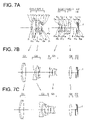
- FIG. 7A , FIG. 7B , and FIG. 7C are diagrams similar to FIG. 1A , FIG. 1B , and FIG. 1C respectively, according to a seventh embodiment of the zoom lens system of the present invention
- FIG. 8A , FIG. 8B , and FIG. 8C are diagrams similar to FIG. 1A , FIG. 1B , and FIG. 1C respectively, according to an eighth embodiment of the zoom lens system of the present invention.
- FIG. 9A , FIG. 9B , and FIG. 9C are diagrams showing a spherical aberration, an astigmatism, a distortion, and a chromatic aberration of magnification at the time of the infinite object point focusing, according to the first embodiment, where, FIG. 9A shows a state at the wide angle end, FIG. 9B shows an intermediate state, and FIG. 9C shows a state at the telephoto end;
- FIG. 10A , FIG. 10B , and FIG. 10C are diagrams similar to FIG. 9A , FIG. 9B , and FIG. 9C respectively, at the time of the infinite object point focusing, according to the second embodiment;
- FIG. 11A , FIG. 11B , and FIG. 11C are diagrams similar to FIG. 9A , FIG. 9B , and FIG. 9C respectively, at the time of the infinite object point focusing, according to the third embodiment;
- FIG. 12A , FIG. 12B , and FIG. 12C are diagrams similar to FIG. 9A , FIG. 9B , and FIG. 9C respectively, at the time of the infinite object point focusing, according to the fourth embodiment;
- FIG. 13A , FIG. 13B , and FIG. 13C are diagrams similar to FIG. 9A , FIG. 9B , and FIG. 9C respectively, at the time of the infinite object point focusing, according to the fifth embodiment;
- FIG. 14A , FIG. 14B , and FIG. 14C are diagrams similar to FIG. 9A , FIG. 9B , and FIG. 9C respectively, at the time of the infinite object point focusing, according to the sixth embodiment;
- FIG. 15A , FIG. 15B , and FIG. 15C are diagrams similar to FIG. 9A , FIG. 9B , and FIG. 9C respectively, at the time of the infinite object point focusing, according to the seventh embodiment;
- FIG. 16A , FIG. 16B , and FIG. 16C are diagrams similar to FIG. 9A , FIG. 9B , and FIG. 9C respectively, at the time of the infinite object point focusing, according to the eighth embodiment;
- FIG. 17 is a diagram describing a correction of a distortion
- FIG. 18 is a front perspective view showing an appearance of a digital camera in which, the zoom lens system according to the present invention is incorporated;
- FIG. 19 is a rear perspective view of the digital camera in FIG. 18 ;
- FIG. 20 is a cross-sectional view of the digital camera in FIG. 18 ;
- FIG. 21 is a structural block diagram of an internal circuit of main components of a digital cameral
- FIG. 22A and FIG. 22B are diagrams describing a function of an image forming optical system (zoom lens system) of the present invention.
- FIG. 23A and FIG. 23B are other diagrams describing the function of the image forming optical system (zoom lens system) of the present invention.
- FIG. 24 is a diagram describing an amount of aspherical deviation.
- a zoom lens system according to the present invention includes in order from an object side thereof
- a first lens unit having positive refracting power a second lens unit having a negative refracting power, and a rear lens group having a positive refracting power, which includes a third lens unit having a positive refracting power, and
- the first lens unit moves to be positioned more toward an object side, than at a wide angle end, at the telephoto end, the second lens unit moves to be positioned more toward an image side, than at the wide angle end, at the telephoto end, the aperture stop moves to be positioned more toward the object side, than at the wide angle end, and at the telephoto end, the third lens unit moves to be positioned more toward the object side, than at the wide angle end, and
- a combined system of the first lens unit and the second lens unit at the wide angle end has a negative refracting power
- the second lens unit is positioned more toward the object side than a position of the second lens unit at the wide angle end, and
- the second lens unit when a state in which, the second lens unit is positioned closest to the object is defined as an intermediate zoom state, at the intermediate zoom state, the first lens unit moves to be positioned more toward the object side, than at the wide angle end, at the intermediate zoom state, the aperture stop moves to be positioned more toward the object side, than at the wide angle end, at the intermediate zoom state, the third lens unit moves to be positioned more toward the object side, than at the wide angle end, and at the intermediate zoom state, an object point of the third lens unit moves to be positioned more toward the object side, than at the wide angle end, and
- the zoom lens system satisfies the following conditional expression. 5.0 ⁇ f t /f w ⁇ 15.0 (21)
- f w is a focal length at the wide angle end, of the entire zoom lens system
- f t is a focal length at the telephoto end, of the entire zoom lens system.
- the zoom lens system of the present invention includes in order from an object side thereof, a first lens unit having a positive refracting power, a second lens unit having a negative refracting power, and a a rear lens unit having a positive refracting power, which includes third lens unit having a positive refracting power.
- the first lens unit moves to be positioned more toward an object side, than at the wide angle end, at telephoto end, the second lens unit moves to be positioned more toward an image side, than at the wide angle end, and at the telephoto end, the third lens unit moves to be positioned more toward the object side, than at the wide angle end.
- an aperture stop is disposed between the second lens unit and the third lens unit, and at the telephoto end, the aperture stop moves to be positioned more toward the object side, than at the wide angle end. Accordingly, a height of incidence of off-axis ray which is incident on the third lens unit is suppressed, which is advantageous for making small a size of the third lens unit, and it becomes easy to secure a space in which the third lens unit moves.
- an arrangement is made such that a combined system of the first lens unit and the second lens unit has a negative refracting power at the wide angle end, and at the time of zooming of the second lens unit from the wide angle end to the telephoto end, an area which moves in a locus of convexity toward the object side is imparted.
- the second lens unit is positioned more toward the object side than a position of the second lens unit at the wide angle end, and when a state in which, the second lens unit is positioned closest to the object is defined as an intermediate zoom state, at the intermediate zoom state, the first lens unit moves to be positioned more toward the object side, than at the wide angle end, at the intermediate zoom step, the aperture stop moves to be positioned more toward the object side, than at the wide angle end, at the intermediate zoom state, the third lens unit moves to be positioned more toward the object side, than at the wide angle end, and at the intermediate zoom state, an object point of the third lens unit moves to be positioned more toward the object side, than at the wide angle end.
- FIG. 22A is a diagram describing a case in which an object point (O G3 ) of the third lens unit moves toward the image side at the time of zooming from the wide angle end to a state in a half way of zooming.
- FIG. 22B is a diagram describing a case in which the object point (O G3 ) of the third lens unit moves toward the object side at the time of zooming from the wide angle end to a state in a half way of zooming.
- a retro focus lens system at a wide angle end is formed along with the rear lens group (GR) having the positive refracting power.
- the third lens unit By moving the third lens unit to be positioned more toward the object side at the intermediate zoom state than at the wide angle end, it is possible to let the third lens unit have a zooming load at the wide angle end (zooming from the wide angle end to the intermediate zoom state).
- Decreasing an outer diameter of the first lens unit at the wide angle end in particular, is advantageous for making compact the size in a direction of thickness of the lens.
- the abovementioned movement of the aperture stop is advantageous for securing a zoom range in which an angle of incidence on an image pickup element is favorable in the zoom range.
- the second lens unit may be moved toward the image side such that the second lens unit is positioned more toward the image side at the telephoto end than at the wide angle end, and the second lens unit may be let to have a zooming function. It is possible to reduce a load of zooming on the third lens unit at the telephoto end. Moreover, it is possible to make it easy to suppress a change in F NO , and it is advantageous for securing brightness at the telephoto end.
- Conditional expression (21) is an expression which specifies a zooming ratio of the zoom lens system.
- a lower limit value is less than a lower limit value in the conditional expression (21)
- the zoom lens system satisfies the following conditional expressions with regard to the zooming from the wide angle end to the telephoto end. 0.06 ⁇ 2 G —ws /f w ⁇ 1.5 (1) ⁇ 0.6 ⁇ 2 G —st /f t ⁇ 0.02 (2)
- ⁇ 2G —ws is a difference in a distance of a position of the second lens unit at the wide angle end and a position of the second lens unit at the intermediate zoom state
- ⁇ 2G —st is a difference in a distance of a position of the second lens unit at the intermediate zoom state and a position of the second lens unit at the telephoto end
- f w is a focal length at the wide angle end, of the entire zoom lens system
- f t is a focal length at the telephoto end, of the entire zoom lens system
- a reference numeral in a direction of advancement toward the image side has a minus sign
- a reference numeral in a direction of advancement toward the object side has a plus sign
- Conditional expression (1) is an expression which specifies an amount of movement of the second lens unit from the wide angle end to the intermediate zoom state.
- Conditional expression (2) is an expression which specifies an amount of movement of the second lens unit from the intermediate zoom state to the telephoto end.
- conditional expression (1) It is preferable to let the lower limit value in conditional expression (1) to be 0.09, and a lower limit value of 0.12 is more preferable. It is preferable to let the upper limit value in conditional expression (1) to be 1.0, and an upper limit value of 0.5 is more preferable. It is preferable to let the lower limit value in conditional expression to be ⁇ 0.3, and a lower limit value of ⁇ 0.15 is more preferable. It is preferable to let the upper limit value in conditional expression (2) to be ⁇ 0.03, and an upper limit value of ⁇ 0.04 is more preferable.
- the zoom lens system satisfies the following conditional expression at the time of zooming from the wide angle end to the telephoto end.
- 0.9 ⁇ 1 G —ws / ⁇ 2 G —ws ⁇ 10.0 (A) ⁇ 2.0 ⁇ 1 G —st / ⁇ 2 G —st ⁇ 0.3 (B) 2.0 ⁇ 3 G —ws / ⁇ 2 G —ws ⁇ 10.0 (C) ⁇ 1.5 ⁇ 3 G —st / ⁇ 2 G —st ⁇ 0.5 (D)
- ⁇ 1G —ws is a difference in a distance of a position of the first lens unit at the wide angle end and a position of the first lens unit at the intermediate zoom state
- ⁇ 1G —st is a difference in a distance of a position of the first lens unit at the intermediate zoom state and a position of the first lens unit at the telephoto end
- ⁇ 3G —ws is a difference in a distance of a position of the third lens unit at the wide angle end and a position of the third lens unit at the intermediate zoom state
- ⁇ 3G —st is a difference in a distance of a position of the third lens unit at the intermediate zoom state and a position of the third lens unit at the telephoto end
- a reference numeral in a direction of advancement toward the image side has a minus sign and a reference numeral in a direction of advancement toward the object side has a plus sign.
- Conditional expressions (A), (B), (C), and (D) are expressions which specify a relation of the movement of the first lens unit, the second lens unit, and the third lens unit.
- Conditional expressions (A) and (B) are expressions which specify about a relationship between the movement of the first lens unit and the movement of the second lens unit.
- Conditional expressions (C) and (D) are expressions which specify a relationship between the movement of the second lens unit and the movement of the third lens unit.
- conditional expression (A) it is preferable to let the lower limit value in conditional expression (A) to be 1.0. It is more preferable to let the upper limit value in conditional expression (A) to be 6.0. It is preferable to let the lower limit value in conditional expression (B) to be ⁇ 0.1. It is more preferable to let the upper limit value in conditional expression (B) to be 0.0. It is preferable to let the lower limit value in conditional expression (C) to be 2.5. It is more preferable to let the upper limit value in conditional expression (C) to be 7.0. It is preferable to let the lower limit value in conditional expression (D) to be ⁇ 1.2. It is more preferable to let the upper limit value in conditional expression (D) to be 0.3.
- the rear lens group includes a fourth lens unit having a positive refracting power, which is disposed toward the image side of the third lens unit, and the zoom lens system is a four-unit zoom lens system.
- the rear lens group having a positive refracting power By letting the rear lens group having a positive refracting power to be two lens unit having the positive refracting power, it is further advantageous for shorting the overall length of the zoom lens system. Particularly, when the fourth lens unit is let to be positioned more toward the image side at the telephoto end, than at the wide angle end, the zooming function is also borne by the fourth lens unit, and it is even more advantageous for securing the zooming ratio.
- ⁇ 3Gw denotes a lateral magnification of the third lens unit, at a wide angle end
- ⁇ 3Gs denotes a lateral magnification of the third lens unit, at the intermediate zoom state
- ⁇ 4Gw denotes a lateral magnification of the fourth lens unit, at the wide angle end
- ⁇ 4Gs denotes a lateral magnification of the fourth lens unit, at the intermediate zoom state.
- Conditional expression (E) is an expression which specifies a zooming ratio of the fourth lens unit at the wide angle side.
- conditional expression (E) it becomes easy to make small the amount of movement of the fourth lens unit, which is advantageous for making small the size of the apparatus.
- a lower limit value is lower than a lower limit value in conditional expression (E)
- Conditional expression (F) is an expression which specifies a zooming ratio of the third lens unit at the wide angle side (end).
- Conditional expression (G) is an expression which specifies a lateral magnification ratio at the wide angle end of the third lens unit.
- conditional expression (E) It is preferable to let the lower limit value in conditional expression (E) to be 0.9. Further, it is more preferable to let the lower limit value to be 1.01 for making it advantageous for the magnification at the wide angle side of the fourth lens unit. It is preferable to let the upper limit value in conditional expression (E) to be 1.2. It is preferable to let the lower limit value in conditional expression (F) to be 1.4. It is preferable to let the upper limit value in conditional expression (F) to be 2.0. It is preferable to let the lower limit value in conditional expression (G) to be ⁇ 1.1. It is preferable to let the upper limit value in conditional expression (G) to be ⁇ 0.9.
- the rear lens group includes a fourth lens unit having a negative refracting power and a fifth lens unit having a positive refracting power, which are disposed toward the image side of the third lens unit, and in the intermediate zoom state, the fourth lens unit moves to be positioned more toward the object side, than at the wide angle end, and that the zoom lens system is a five-unit zoom lens system.
- ⁇ 34Gw denotes a lateral magnification of a combined system of the third lens unit and the fourth lens unit, at a wide angle end
- ⁇ 34Gs denotes a lateral magnification of the combined system of the third lens unit and the fourth lens unit, at the intermediate zoom state
- ⁇ 5Gw denotes a lateral magnification of the fifth lens unit, at the wide angle end
- ⁇ 5Gs denotes a lateral magnification of the fifth lens unit, at the intermediate zoom state.
- Conditional expression (H) is an expression which specifies a zooming ratio of the fifth lens unit at the wide angle side.
- conditional expression (H) it becomes easy to make small an amount of movement of the fifth lens unit, which is advantageous for making small the size of the apparatus.
- a lower limit value is not lower that a lower limit value in conditional expression (H)
- Conditional expression (I) is an expression which specifies a zooming ratio of a combined system of the third lens unit and the fourth lens unit at the wide angle side.
- Conditional expression (J) is an expression which specifies a lateral magnification at the wide angle end of the combined system of the third lens unit and the fourth lens unit.
- conditional expression (H) It is preferable to let the lower limit value in conditional expression (H) to be 0.9, and a lower limit value of 1.01 is more preferable. It is preferable to let the upper limit value in conditional expression (H) to be 1.2. It is preferable to let the lower limit value in conditional expression (I) to be 1.4. It is preferable to let the upper limit value in the conditional expression (I) to be 2.0. It is preferable to let the lower limit value in conditional expression (J) to be ⁇ 1.1. It is preferable to let the upper limit value in conditional expression (J) to be ⁇ 0.9.
- a lens surface closest to the object, of the second lens unit is a concave surface
- a lens surface closest to the image, of the first lens unit is a convex surface
- the second lens unit includes two negative lenses namely a first negative lens (hereinafter, called appropriately as a ‘negative lens L 2n1 ’) which is disposed closest to the object side in the second lens unit, and a second negative lens (hereinafter, called appropriately as a ‘negative lens L 2n2 ’) which is disposed toward an image side of the first negative lens, and a first positive lens (hereinafter, called appropriately as a ‘positive lens L 2p ’), and that the total number of lenses included in the second lens unit is three.
- a first negative lens hereinafter, called appropriately as a ‘negative lens L 2n1 ’
- a second negative lens hereinafter, called appropriately as a ‘negative lens L 2n2 ’
- a first positive lens hereinafter, called appropriately as a ‘positive lens L 2p ’
- the zoom lens system satisfies the following conditional expression. ⁇ 0.5 ⁇ SF 2n1 ⁇ 1.0 (3)
- R 2n1f is a paraxial radius of curvature of a surface on the object side, of the first negative lens
- R 2n1r is a paraxial radius of curvature of a surface on an image side of the first negative.
- Conditional expression (3) is an expression for balancing the compactness and securing the performance while securing a refracting power of the negative lens closest to the object, in the second lens unit.
- the zoom lens system may satisfy the following conditional expression. 0 ⁇ SF 2n1 ⁇ 0.9 (3′)
- the zoom lens system may satisfy the following conditional expression. 0.25 ⁇ SF 2n1 ⁇ 0.8 (3′′)
- the upper limit value and the lower limit value in conditional expression (3) may be let to be an upper limit value or a lower limit value of conditional expressions (3′) and (3′′). Similar changes are possible in a lower limit value and an upper limit value in conditional expressions shown below.
- an appropriate material may be set for the negative lens L 2n1 in the second lens unit.
- the zoom lens system satisfies the following conditional expressions. 1.78 ⁇ n d2n1 ⁇ 2.20 (4) 35 ⁇ d2n1 ⁇ 50 (5)
- n d2n1 denotes a refractive index for a d-line, of the negative lens L 2n1 , and
- ⁇ d2n1 denotes an Abbe's number for the negative lens L 2n1 .
- the zoom lens system may satisfy the following conditional expressions. 1.79 ⁇ n d2n1 ⁇ 1.95 (4′) 37 ⁇ d2n1 ⁇ 47 (5′)
- the zoom lens system may satisfy further, the following conditional expressions. 1.80 ⁇ n d2n1 ⁇ 1.90 (4) 40 ⁇ d2n1 ⁇ 43 (5)
- an appropriate material may be set for a negative lens L 2n2 in the second lens unit. Concretely, the following arrangement may be made. 1.78 ⁇ n d2n2 ⁇ 2.00 (6) 35 ⁇ d2n2 ⁇ 50 (7)
- n d2n2 denotes a refractive index for a d-line, of the negative lens L 2n2 , and
- ⁇ d2n2 denotes an Abbe's number for the negative lens L 2n2 .
- Making an arrangement such that a lower limit value is not lower than a lower limit value in conditional expression (7), is advantageous for suppressing the chromatic dispersion and correcting the chromatic aberration.
- the zoom lens system may satisfy the following conditional expressions. 1.79 ⁇ n d2n2 ⁇ 1.95 (6′) 38 ⁇ d2n2 ⁇ 48 (7′)
- the zoom lens system may satisfy further, the following conditional expressions. 1.80 ⁇ n d2n2 ⁇ 1.90 (6′′) 40 ⁇ d2n2 ⁇ 47 (7′′)
- n d2p denotes a refractive index for a d-line, of the positive lens L 2p .
- ⁇ d2p denotes an Abbe's number for the first positive lens.
- Conditional expression (9) is an expression regarding a correction of the chromatic aberration, and in particular, an oblique chromatic aberration of magnification.
- the chromatic aberration occurred due to a substantial negative refracting power, it is preferable to use for the positive lens, a material having a comparatively substantial chromatic dispersion in an appropriate range. It is preferable to secure dispersion and to carry out correction of the chromatic aberration occurred in (at) the negative lens by making an arrangement such that an upper limit value is not higher than an upper limit value in conditional expression (9).
- the zoom lens system may satisfy the following conditional expressions. 1.87 ⁇ n d2p ⁇ 2.15 (8′) 15 ⁇ d2p ⁇ 26 (9′)
- the zoom lens system may further satisfy the following conditional expressions. 1.90 ⁇ n d2p ⁇ 2.12 (8′′) 17 ⁇ d2p ⁇ 21 (9′′)
- the following arrangement is made in the zoom lens system.
- one surface or both surfaces of the negative lens L 2n1 in the second lens unit is or are aspheric, and the zoom lens system satisfies the following conditional expression. 0.005 ⁇ (
- asp 2n1f denotes an aspherical deviation of the negative lens closest to the object, in the second lens unit, at a lens surface toward the object
- asp 2n1r denotes an aspherical deviation of the negative lens closest to the object, in the second lens unit, at a lens surface toward the image
- fw denotes a focal length at the wide angle end, of the entire zoom lens system.
- an aspheric surface may be disposed for at least one lens surface of the negative lens L 21n which is closest to the object, in the second lens unit. Moreover, both the surfaces of the lens L 21n may be let to be aspheric surfaces. Such an arrangement has an effect on a correction of the coma aberration and the image plane curvature.
- an amount of aspherical deviation is a distance from a reference spherical surface up to that lens surface when measured in a direction parallel to an optical axis, at a position of maximum height of incidence of light rays at the wide angle end, at that lens surface, when a spherical surface having a vertex same as an apex of the lens surface, and for which a paraxial radius of curvature of that lens surface is a radius of curvature, is let to be the reference spherical surface, and a direction toward the image is let to be a positive reference numeral.
- the amount of aspherical deviation when the lens surface is spherical or flat is zero.
- the zoom lens system may satisfy the following conditional expression. 0.008 ⁇ (
- the zoom lens system may further satisfy the following conditional expression. 0.01 ⁇ (
- the zoom lens system may have the following arrangement.
- the second lens unit includes in order from the object side thereof, the negative lens L 2n1 , the negative lens L 2n2 , and the positive lens L 2p . Accordingly, it becomes easy to bring principal points of the second lens unit toward the object, which is advantageous for making small the diameter.
- the zoom lens system may have the following arrangement.
- the second lens unit includes in order from the object side thereof, the negative lens L 2n1 , the positive lens L 2p , and the negative lens L 2n2 . Accordingly, it becomes easy to suppress a change in the spherical aberration at the time of zooming.
- the zoom lens system has the following arrangement.
- the first lens unit includes a first positive lens (hereinafter, called appropriately as a ‘positive lens L 1p ’) and a first negative lens (hereinafter, called appropriately as a ‘negative lens L 1n ’), and that the total number of lenses in the first lens unit is two.
- the chromatic aberration at the telephoto end particularly is susceptible to be problematic. Therefore, it is preferable from the point of chromatic aberration that the first lens unit includes the positive lens and the negative lens.
- the zoom lens system has the following arrangement.
- each of the negative lens L 1n and the positive lens L 1p in the first lens unit is a single lens.
- the zoom lens system may have the following arrangement.
- a distance on the optical axis between the negative lens L 1n and the positive lens L 1p of the first lens unit satisfies the following conditional expression. 0.0 ⁇ d 1np /d 1 ⁇ 0.2 (12)
- d 1np denotes the distance on the optical axis between the first negative lens and the first positive lens in the first lens unit
- d 1 denotes an overall thickness of the first lens unit on the optical axis.
- the zoom lens system may satisfy the following conditional expression. 0.0 ⁇ d 1np /d 1 ⁇ 0.1 (12′)
- the zoom lens system may further satisfy the following conditional expression. 0.0 ⁇ d 1np /d 1 ⁇ 0.03 (12′′)
- the zoom lens system may have the following arrangement.
- the negative lens L 1n and the positive lens L 1p in the first lens unit are cemented. Accordingly, it is possible to correct favorably a chromatic aberration of magnification at the wide angle end and a longitudinal chromatic aberration at the telephoto end. Moreover, it is possible to reduce a decline in yield which is caused due to a deterioration of performance due to a relative decentering, which leads to a reduction in cost.
- an optimum material may be set for the positive lens L 1p and the negative lens L 1n in the first lens unit.
- the zoom lens system may satisfy the following conditional expressions. 1.47 ⁇ n d1p ⁇ 1.90 (13) 40 ⁇ d1p ⁇ 85 (14) 1.75 ⁇ n d1n ⁇ 2.05 (15) 12 ⁇ d1n ⁇ 31 (16)
- n d1p denotes a refractive index for a d-line, of the positive lens L 1p ,
- ⁇ d1p denotes an Abbe's number for the positive lens L 1p ,
- n d1n denotes a refractive index for a d-line, of the negative lens L 1n , and
- ⁇ d1n denotes an Abbe's number for the negative lens L 1n .
- an arrangement such that a lower limit value is not lower than a lower limit value in conditional expression (14) the chromatic dispersion is suppressed, which is advantageous for correction of the chromatic aberration.
- Conditional expression (16) is an expression regarding a correction of the chromatic aberration of magnification, and in particular, a correction of a longitudinal chromatic aberration of magnification.
- the chromatic aberration occurred due to a substantial positive refracting power, it is preferable to use for the negative lens, a material having a comparatively substantial chromatic dispersion in an appropriate range. It is appropriate to secure dispersion and to carry out correction of the chromatic aberration occurred at the positive lens by making an arrangement such that an upper limit value is not higher than an upper limit value in conditional expression (16).
- the zoom lens system may satisfy the following conditional expressions. 1.55 ⁇ n d1p ⁇ 1.80 (13′) 45 ⁇ d1p ⁇ 75 (14′) 1.79 ⁇ n d1n ⁇ 2.01 (15′) 15 ⁇ d1n ⁇ 26 (16′)
- the zoom lens system may further satisfy the following conditional expressions. 1.58 ⁇ n d1p ⁇ 1.75 (13′′) 48 ⁇ d1p ⁇ 68 (14′′) 1.83 ⁇ n d1n ⁇ 1.95 (15′′) 17.5 ⁇ d1n ⁇ 24 (16′′)
- the zoom lens system may have the following arrangement.
- the first lens unit includes in order from the object side thereof, the negative lens L 1n and the positive lens L 1p .
- the first lens unit includes in order from the object side thereof, the negative lens L 1n and the positive lens L 1p .
- the zoom lens system may have the following arrangement.
- the third lens unit includes not more than three lenses. This is advantageous for slimming of the lens barrel.
- the zoom lens system may have the following arrangement.
- the third lens unit includes in order from the object side thereof, three lenses namely a positive lens, a positive lens, and a negative lens.
- the positive refracting power of the third lens unit is distributed, and adding the negative lens is advantageous for correction of various aberrations. Allowing to converge axial light ray which is diverged from the second lens unit, by two positive lenses is advantageous for making small the third lens unit. Moreover, by allowing to refract the off-axis light beam, in a direction away from the optical axis, it is possible to secure a height of incidence on an image pickup surface. Moreover, since the principal points of the third lens unit are toward the object, it becomes easy to bring the principal points of the third lens unit at the telephoto end closer to the principal points of the second lens unit, which is advantageous for achieving a high zooming ratio.
- a second positive lens and a negative lens from the object side.
- cementing the positive lens and the negative lens it is possible to carry out more effectively the correction of the longitudinal chromatic aberration.
- it is possible to prevent a degradation of optical performance due to relative decentering of lenses in the assembling process it leads to an improvement in the yield and the reduction of cost.
- the third lens unit it is preferable to dispose one or more aspheric surfaces in the third lens unit. This is effective for correction of the spherical aberration and the coma aberration. Furthermore, it is preferable to let the positive lens closest to the object in the third lens unit to be a biaspherical lens.
- the degradation of optical performance due to the relative decentering of the lenses tends to be substantial.
- both side surfaces of one lens to be aspherical it is possible to carry out a further favorable correction of the spherical aberration and the coma aberration while suppressing the degradation of optical performance due to the relative decentering of the lenses to be small.
- f 2 denotes a focal length of the second lens unit
- f t denotes a focal length of the entire zoom lens system, at a telephoto end.
- the zoom lens system may satisfy the following conditional expression. 0.10 ⁇
- the zoom lens system may further satisfy the following conditional expression. 0.12 ⁇
- the zoom lens system satisfies the following conditional expression regarding the first lens unit. 0.3 ⁇ f 1 /f t ⁇ 0.95 (18)
- f 1 denotes a focal length of the first lens unit
- f t denotes a focal length of the entire zoom lens system, at a telephoto end.
- the zoom lens system may satisfy the following conditional expression. 0.4 ⁇ f 1 /f t ⁇ 0.8 (18′)
- the zoom lens system may further satisfy the following conditional expression. 0.5 ⁇ f 1 /f t ⁇ 0.68 (18′′)
- the zoom lens system satisfies the following conditional expression regarding the refracting power of the third lens unit. 0.1 ⁇ f 3 /f t ⁇ 0.5 (19)
- f 3 denotes a focal length of the third lens unit
- f t denotes a focal length of the entire zoom lens system at the telephoto end.
- the zoom lens system may satisfy the following conditional expression. 0.12 ⁇ f 3 /f t ⁇ 0.40 (19′)
- the zoom lens system may further satisfy the following conditional expression. 0.15 ⁇ f 3 /f t ⁇ 0.30 (19′′)
- the zoom lens system has the following arrangement regarding the lens unit which is disposed closest to the image in the zoom lens system.
- the rear lens group includes a lens unit having a positive refracting power closest to the image, which is different from the third lens unit, and the zoom lens system satisfies the following conditional expression. 0.2 ⁇ f RE /f t ⁇ 0.6 (20)
- f RE denotes a focal length of the lens unit which is positioned closest to the image, in the rear lens group
- f t denotes a focal length of the entire zoom lens system, at a telephoto end.
- the zoom lens system may satisfy the following conditional expression. 0.28 ⁇ f RE /f t ⁇ 0.53 (20′)
- the zoom lens system may further satisfy the following conditional expression. 0.35 ⁇ f RE /f t ⁇ 0.46 (20′′)
- the lens unit closest to the image may be formed of a plastic material.
- the main function of the lens unit closest to the image is to allow to incident light rays efficiently on the electronic image pickup element such as a CCD and a CMOS by disposing an exit pupil at an appropriate position. Due to such function, when the refracting power is set in a range as in the abovementioned conditional expression (20), comparatively substantial refracting power is not necessary, and it is possible to form by a glass having a low refracting power such as a plastic lens. When a plastic lens is used in the lens unit closest to the image, it is possible to suppress the cost to be low, and to provide even lower cost zoom lens system.
- an image pickup apparatus includes a zoom lens of the present invention, and has the following arrangement.
- the image pickup apparatus includes the zoom lens system and an image pickup element which converts an image formed by the zoom lens system to an electric signal.
- the image pickup element satisfies the following conditional expression. 0.4 ⁇ I m /f w ⁇ 0.8 (22)
- I m denotes a maximum image height in an effective image pickup area
- f w denotes a focal length of the entire zoom lens system, at a wide angle end.
- An effective image pickup area is an area of an image pickup surface on an image pickup element, on which an image is displayed and recorded, at when the area changes, an image height in a state of the maximum image height is defined as the maximum image height 1 m.
- the zoom lens system may satisfy the following conditional expression. 0.45 ⁇ I m /f w ⁇ 0.7 (22′)
- the zoom lens system may further satisfy the following conditional expression. 0.55 ⁇ I m /f w ⁇ 0.6 (22′′)
- the aperture stop may be moved integrally with the third lens unit at the time of zooming from the wide angle end to the telephoto end. Since the height of the off-axis light rays may be lowered, it is even more advantageous for making small the third lens unit. Further, the aperture stop and a shutter mechanism may be let to be an integral structure. Accordingly, the purpose is served without making small a size of a shutter unit, and with a small dead space at the time of moving the aperture stop and the shutter unit.
- a flare aperture may be disposed at a location other than a location of the aperture stop.
- the flare aperture may be disposed at any location such as an object side of the first lens unit, between the first lens unit and the second lens unit, between the second lens unit and the third lens unit, between the lens units in the rear lens group, and between the rear lens group and an image plane.
- An arrangement may be made to cut the flare light rays by a frame member which holds the lens unit, or the flare aperture may be formed by a member other than the frame member.
- a direct printing may be carried out, or a paint may be applied, or a seal may be adhered to the lens.
- the shape may be any shape such as a circular shape, an elliptical shape, a rectangular shape, a polygon, and an area surrounded by a function curve.
- not only harmful light beam, but also light beam such as a coma flare around a screen may be cut.
- the ghost and the flare may be reduced by applying an antireflection coating to each lens.
- a multi-coating is desirable, as the multi-coating is capable of reducing effectively the ghost and the flare.
- an infra-red rays cutting coating may be applied to the lens surfaces and cover glasses.
- the focusing is carried out at a lens unit closest to the image in the zoom lens system. Since it is easy to make light the lens unit closest to the image, it is possible to reduce a load exerted on a motor at the time of focusing. Furthermore, since the overall length does not change at the time of focusing, and a drive motor can be disposed inside a lens frame, it is advantageous for making the lens frame compact.
- the focusing may be carried out by the first lens unit, the second lens unit, and the third lens unit.
- the focusing may also be carried out by moving a plurality of lens units.
- the focusing may be carried out by drawing out the entire lens system, or by drawing out some of the lenses, or the focusing may be carried over.
- the shading of brightness in a portion around an image may be reduced by shifting a micro lens of the CCD.
- a design of the micro lens of the CCD may be changed according to an angle of incidence of light rays for each image height.
- an amount of degradation in the portion around an image may be corrected by an image processing.
- a distortion may be let to occur intentionally in the optical system, and the distortion may be corrected by carrying out electrically an image processing after taking pictures.
- each of the abovementioned inventions satisfies arbitrarily a plurality of conditional expressions simultaneously.
- each conditional expression only an upper limit value or a lower limit value of a numerical range of further restricted conditional expressions may be restricted.
- various arrangements described above may be combined arbitrarily.
- the present invention it is possible to provide a compact zoom lens system having a high zooming ratio and which is capable of securing oblique incident rays in a zoom range near the wide angle end, and which is bright even at the wide angle end, and an electronic image pickup apparatus in which this zoom lens system is used.
- a zoom lens system and an electronic image pickup apparatus will be described below in detail by referring to the accompanying diagrams.
- the present invention is not restricted to the embodiments described below.
- a further compact zoom lens system having a high zooming ratio of about seven times, which is capable of securing easily oblique incident rays in a zoom range near a wide angle end, and making bright F NO at a telephoto end is realized.
- it is a zoom lens system in which an image quality of an image taken is maintained to be favorable and which is a low cost zoom lens system suitable for an electronic image pickup apparatus such as a CCD and a CMOS.
- FIG. 1A , FIG. 1B , and FIG. 1C to FIG. 8A , FIG. 8B , and FIG. 8C Lens cross-sectional views at a wide angle end, an intermediate state, and at a telephoto end of an infinite object point focusing of the first embodiment to the eighth embodiment are shown in FIG. 1A , FIG. 1B , and FIG. 1C to FIG. 8A , FIG. 8B , and FIG. 8C .
- G 1 denotes a first lens unit
- G 2 denotes a second lens unit
- S denotes an aperture stop
- G 3 denotes a third lens unit
- G 4 denotes a fourth lens unit
- G 5 denotes a fifth lens unit
- F denotes a parallel flat plate which forms a low pass filter in which, a wavelength region restricting coating which restricts infrared light is applied
- C denotes a parallel flat plate of carbon glass of an electronic image pickup element (CCD)
- I denotes an image plane (last plane).
- a multilayered film for restricting a wavelength region may be applied to a surface of the carbon glass C.
- the carbon glass C may be let to have a low pass filter effect.
- each numerical data is data in a state when focused at infinite object.
- a unit of a length for each value is mm, and a unit of angle is degrees (°). Focusing in each embodiment is carried out by moving a lens unit closest to an image.
- An image height in each embodiment is 3.84 mm.
- zoom data are values at a wide angle end (WE), at an intermediate zoom state (ST) defined in the present invention, and at a telephoto end (TE).
- a zoom lens system in the first embodiment includes, in order form an object side thereof, a first lens unit G 1 having a positive refracting power, a second lens unit G 2 having a negative refracting power, an aperture stop S, a third lens unit G 3 having a positive refracting power, and a fourth lens unit G 4 having a positive refracting power.
- the first lens unit moves toward the object side
- the second lens unit G 2 after moving once toward the object side, is turned over, and moves toward an image side
- the third lens unit G 3 after moving integrally with the aperture stop S, once toward the object side, is turned over, and moves toward the image side
- the fourth lens unit G 4 moves toward the image side.
- the first lens unit G 1 includes a first negative meniscus lens having a convex surface directed toward the object side, and a second biconvex positive lens.
- the first negative meniscus lens and the second biconvex positive lens are cemented.
- the second lens unit G 2 includes a third biconcave negative lens, a fourth biconcave negative lens, and a fifth positive meniscus lens having a convex surface directed toward the object side.
- the third lens unit G 3 includes a sixth biconvex positive lens, a seventh biconvex positive lens, and an eighth biconcave negative lens.
- the seventh biconvex positive lens and the eighth biconcave negative lens are cemented.
- the fourth lens unit G 4 includes a ninth biconvex positive lens. A lens vertex of a tenth surface is positioned at the object side of the aperture stop.
- An aspheric surface is used for six surfaces namely, a surface on the image side of the second biconvex positive lens, both surfaces of the third biconcave negative lens, both surfaces of the sixth biconvex positive lens, and a surface on the object side of the ninth biconvex positive lens.
- a zoom lens system in the second embodiment includes, in order from the object side thereof, a first lens unit G 1 having a positive refracting power, a second lens unit G 2 having a negative refracting power, an aperture stop S, a third lens unit G 3 having a positive refracting power, and a fourth lens unit G 4 having a positive refracting power.
- the first lens unit G 1 moves toward the object side
- the second lens unit G 2 after moving once toward the object side, is turned over, and moves toward the image side
- the third lens unit G 3 moves integrally with the aperture stop S toward the object side
- the fourth lens unit G 4 moves toward the image side.
- the first lens unit G 1 includes a first negative meniscus lens having a convex surface directed toward the object side and a second biconvex positive lens.
- the second lens unit G 2 includes a third biconcave negative lens, a fourth biconvex positive lens, and a fifth biconcave negative lens.
- the third lens unit G 3 includes a sixth biconvex positive lens, a seventh positive meniscus lens having a convex surface directed toward the object side, and an eighth negative meniscus lens having a convex surface directed toward the object side.
- the seventh positive meniscus lens and the eighth negative meniscus lens are cemented.
- the fourth lens unit G 4 includes a ninth biconvex positive lens.
- An aspheric surface is used for seven surfaces namely a surface on the image side of the second biconvex positive lens, both surfaces of the third biconcave negative lens, both surfaces of the sixth biconvex positive lens, and both surfaces of the ninth biconvex positive lens.
- a zoom lens system in the third embodiment includes, in order from the object side thereof, a first lens unit G 1 having a positive refracting power, a second lens unit G 2 having a negative refracting power, an aperture stop S, a third lens unit G 3 having a positive refracting power, and a fourth lens unit G 4 having a positive refracting power.
- the first lens unit G 1 moves toward the object side
- the second lens unit G 2 after moving once toward the object side, is turned over, and moves toward the image side
- the third lens unit G 3 moves integrally with the aperture stop S toward the object side
- the fourth lens unit G 4 moves toward the image side.
- the first lens unit G 1 includes a first negative meniscus lens having a convex surface directed toward the object side and a second biconvex positive lens.
- the first negative meniscus lens and the second biconvex positive lens are cemented.
- the second lens unit G 2 includes a third biconcave negative lens, a fourth positive meniscus lens having a convex surface directed toward the object side, and a fifth biconcave negative lens.
- the third lens unit G 3 includes a sixth biconvex positive lens, a seventh positive meniscus lens having a convex surface directed toward the object side, and an eighth negative meniscus lens having a convex surface directed toward the object side.
- the seventh positive meniscus lens and the eighth negative meniscus lens are cemented.
- the fourth lens unit G 4 includes a ninth biconvex positive lens.
- An aspheric surface is used for seven surfaces namely, a surface on the image side of the second biconvex positive lens, both surfaces of the third biconcave negative lens, both surfaces of the sixth biconvex positive lens, and both surfaces of the ninth biconvex positive lens.
- a zoom lens system in the fourth embodiment includes, in order from the object side thereof, a first lens unit G 1 having a positive refracting power, a second lens unit G 2 having a negative refracting power, an aperture stop S, a third lens unit G 3 having a positive refracting power, and a fourth lens unit G 4 having a positive refracting power.
- the first lens unit G 1 moves toward the object side
- the second lens unit G 2 after moving once toward the object side, is turned over, and moves toward the image side
- the third lens unit G 3 moves integrally with the aperture stop S toward the object side
- the fourth lens unit G 4 moves toward the image side.
- the first lens unit G 1 includes a first negative meniscus lens having a convex surface directed toward the object side and a second biconvex positive lens.
- the first negative meniscus lens and the second biconvex positive lens are cemented.
- the second lens unit G 2 includes a third biconcave negative lens, a fourth positive meniscus lens having a convex surface directed toward the object side, and a fifth biconcave negative lens.
- the third lens unit G 3 includes a sixth biconvex positive lens, a seventh positive meniscus lens having a convex surface directed toward the object side, and an eighth negative meniscus lens having a convex surface directed toward the object side.
- the seventh positive meniscus lens and the eighth negative meniscus lens are cemented.
- the fourth lens unit G 4 includes a ninth biconvex positive lens.
- An aspheric surface is used for seven surfaces namely, a surface on the image side of the second biconvex positive lens, both surfaces of the third biconcave negative lens, both surfaces of the sixth biconvex positive lens, and both surfaces of the ninth biconvex positive lens.
- a zoom lens system in the fifth embodiment includes in order from the object side thereof, a first lens unit G 1 having a positive refracting power, a second lens unit G 2 having a negative refracting power, an aperture stop S, a third lens unit G 3 having a positive refracting power, and a fourth lens unit G 4 having a positive refracting power.
- the first lens unit G 1 moves toward the object side
- the second lens unit G 2 after moving once toward the object side, is turned over, and moves toward the image side
- the third lens unit G 3 moves integrally with the aperture stop S toward the object side
- the fourth lens unit G 4 moves toward the image side.
- the first lens unit G 1 includes a first negative meniscus lens having a convex surface directed toward the object side and a second biconvex positive lens.
- the first negative meniscus lens and the second biconvex positive lens are cemented.
- the second lens unit G 2 includes a third biconcave negative lens, a fourth biconcave negative lens, and a fifth biconvex positive lens.
- the fourth biconcave negative lens and the fifth biconvex positive lens are cemented.
- the third lens unit G 3 includes a sixth biconvex positive lens, a seventh biconvex positive lens, and an eighth biconcave negative lens.
- the seventh biconvex positive lens and the eighth biconcave negative lens are cemented.
- the fourth lens unit G 4 includes a ninth biconvex positive lens.
- An aspheric surface is used for six surfaces namely, a surface on the image side of the second biconvex positive lens, both surfaces of the third biconcave negative lens, both surfaces of the sixth biconvex positive lens, and a surface on the image side of the ninth biconvex positive lens.
- a zoom lens system in the sixth embodiment includes, in order from the object side thereof, a first lens unit G 1 having a positive refracting power, a second lens unit G 2 having a negative refracting power, an aperture stop S, a third lens unit G 3 having a positive refracting power, and a fourth lens unit G 4 having a positive refracting power.
- the first lens unit G 1 moves toward the object side
- the second lens unit G 2 after moving once toward the object side, is turned over, and moves toward the image side
- the third lens unit G 3 after moving integrally with the aperture stop S once toward the object side, is turned over, and moves toward the image side
- the fourth lens unit G 4 after moving once toward the object side, is turned over, and moves toward the image side.
- the first lens unit G 1 includes a first negative meniscus lens having a convex surface directed toward the object side and a second biconvex positive lens.
- the first negative meniscus lens and the second biconvex positive lens are cemented.
- the second lens unit G 2 includes a third biconcave negative lens, a fourth biconcave negative lens, and a positive meniscus lens having a convex surface directed toward the object side.
- the third lens unit G 3 includes a sixth biconvex positive lens, a seventh biconvex positive lens, and an eighth biconcave negative lens.
- the seventh biconvex positive lens and the eighth biconcave negative lens are cemented.
- the fourth lens unit G 4 includes a ninth biconvex positive lens. A lens apex of a tenth surface is positioned on the object side of the aperture stop S.
- An aspheric surface is used for six surfaces namely a surface on the image side of the second biconvex positive lens, both surfaces of the third biconcave negative lens, both surfaces of the sixth biconvex positive lens, and a surface on the image side of the ninth biconvex positive lens.
- a zoom lens system in the seventh embodiment includes, in order from the object side thereof, a first lens unit G 1 having a positive refracting power, a second lens unit G 2 having a negative refracting power, an aperture stop S, a third lens unit G 3 having a positive refracting power, and a fourth lens unit G 4 having a positive refracting power.
- the first lens unit G 1 moves toward the object side
- the second lens unit G 2 after moving once toward the object side, is turned over, and moves toward the image side
- the third lens unit G 3 moves integrally with the aperture stop S toward the object side
- the fourth lens unit G 4 moves toward the image side.
- the first lens unit G 1 includes a first negative meniscus lens having a convex surface directed toward the object side and a second biconvex positive lens.
- the first negative meniscus lens and the second biconvex positive lens are cemented.
- the second lens unit G 2 includes a third biconcave negative lens, a fourth positive meniscus lens having a convex surface directed toward the object side, and a fifth biconcave negative lens.
- the third lens unit G 3 includes a sixth biconvex positive lens, a seventh positive meniscus lens having a convex surface directed toward the object side, and an eighth negative meniscus lens having a convex surface directed toward the object side.
- the seventh positive meniscus lens and the eighth negative meniscus lens are cemented.
- the fourth lens unit G 4 includes a ninth biconvex positive lens.
- An aspheric surface is used for seven surfaces namely, a surface on the image side of the second biconvex positive lens, both surfaces of the third biconcave negative lens, both surfaces of the sixth biconvex positive lens, and both surfaces of the ninth biconvex positive lens.
- a zoom lens system in the eighth embodiment includes, in order from the object side thereof, a first lens unit G 1 having a positive refracting power, a second lens unit G 2 having a negative refracting power, an aperture stop S, a third lens unit G 3 having a positive refracting power, a fourth lens unit G 4 having a negative refracting power, and a fifth lens unit G 5 having a positive refracting power.
- the first lens unit G 1 moves toward the object side
- the second lens unit G 2 after moving once toward the object, is turned over, and moves toward the image side
- the third lens unit G 3 moves integrally with the aperture stop S toward the object side
- the fourth lens unit G 4 moves toward the object side
- the fifth lens unit G 5 moves toward the image side.
- the first lens unit G 1 includes a first negative meniscus lens having a convex surface directed toward the object side and a second biconvex positive lens.
- the first negative meniscus lens and the second biconvex positive lens are cemented.
- the second lens unit G 2 includes a third biconcave negative lens, a fourth biconvex positive lens, and a fifth biconcave negative lens.
- the third lens unit G 3 includes a sixth biconvex positive lens.
- the fourth lens unit G 4 includes a seventh positive meniscus lens having a convex surface directed toward the object side and an eighth negative meniscus lens having a convex surface directed toward the object side.
- the seventh positive meniscus lens and the eighth negative meniscus lens are cemented.
- the fifth lens unit G 5 includes a ninth biconvex positive lens.
- An aspheric surface is used for seven surfaces namely, a surface on the image side of the second biconvex positive lens, both surfaces of the third biconcave negative lens, both surfaces of the sixth biconvex positive lens, and both surfaces of the ninth biconvex positive lens.
- f denotes a focal length of the entire zoom lens system
- BF denotes a back focus
- each of f 1 , f 2 , . . . denotes a focal length of each lens unit
- 1 m denotes an image height
- F NO denotes an F number
- ⁇ denotes a half image angle
- WE denotes a wide angle end
- ST denotes an intermediate state
- TE denotes a telephoto end
- each of r 1 , r 2 , . . . denotes a radius of curvature of each lens surface
- each of n d1 , n d2 , . . . denotes a refractive index of each lens for a d-line
- each of ⁇ d1 , ⁇ d2 , . . . denotes an Abbe's number for each lens.
- the overall length of the lens system which will be described later is a length which is obtained by adding the back focus to a distance from the first lens surface up to the last lens surface.
- BF back focus
- r denotes a paraxial radius of curvature
- K denotes a conical coefficient
- a 4 , A 6 , A 8 , A 10 , and A 12 denote aspherical-surface coefficients of a fourth order, a sixth order, an eight order, a tenth order, and a twelfth order respectively.
- e ⁇ n ‘e ⁇ n ’ (where, n is an integral number) indicates ‘10 ⁇ n ’.
- A means that the surface is an aspheric surface
- S means that the surface is an aperture stop
- SA spherical aberration
- AS astigmatism
- DT distortion
- CC chromatic aberration of magnification
- ⁇ is a half image angle
- Example 1 Example 2
- Example 3 Example 4 (1) ⁇ 2G ws /f w 0.351 0.247 0.300 0.476 (2) ⁇ 2G st /f t ⁇ 0.128 ⁇ 0.138 ⁇ 0.131 ⁇ 0.124
- A ⁇ 1G ws / ⁇ 2G ws 3.308 4.863 4.026 1.011
- B ⁇ 1G st / ⁇ 2G st ⁇ 0.154 ⁇ 0.086 ⁇ 0.179 ⁇ 1.197
- C ⁇ 3G ws / ⁇ 2G ws 2.916 4.470 3.771 2.369
- D ⁇ 3G st / ⁇ 2G st 0.028 ⁇ 0.141 ⁇ 0.138 ⁇ 0.233
- E ⁇ 4Gs / ⁇ 4Gw 1.086 1.126 1.134 1.027
- F ⁇ 3Gs / ⁇ 3Gw 1.517 1.496 1.526 1.686 (G) ⁇ 3Gw ⁇ 1.050 ⁇ 0.943
- the antireflection coating is applied to a surface of a lens in contact with air.
- a refractive index of an adhesive is sufficiently higher than a refractive index of air. Therefore, in many cases, a reflectance is originally of the level of a single-layer coating, or lower, and the coating is applied in few cases. However, when the antireflection coating is applied positively even to the cemented surface, it is possible to reduce further the ghost and the flare, and to achieve a more favorable image.
- a glass material having a high refractive index has been widely used in an optical system of cameras, for having a high effect on the aberration correction.
- the glass material having a high refractive index is used as a cemented lens, a reflection at the cemented surface becomes unignorable. In such a case, applying the antireflection coating on the cemented surface is particularly effective.
- coating materials such as Ta 2 O 5 , TiO 2 , Nb 2 O 5 , ZrO 2 , HfO 2 , CeO 2 , SnO 2 , In 2 O 3 , ZnO, and Y 2 O 3 having a comparatively higher refractive index, and coating materials such as MgF 2 , SiO 2 , and Al 2 O 3 having a comparatively lower refractive index may be selected appropriately, and set to a film thickness which satisfies phase conditions.
- the coating on the cemented surface may also be let to be a multi layer coating.
- a film thickness and a coating material of number of films not less than in two layers it is possible to reduce further the reflectance, and to control spectral characteristics and angular characteristics.
- a point P 1 on a circumference of an arbitrary radius r 1 ( ⁇ ) positioned at an inner side of a circle of radius R is moved to a point P 2 on a circumference of a radius r 1 ′( ⁇ ) which is to be corrected, directed toward a center of the circle.
- a point Q 1 on a circumference of an arbitrary radius r 2 ( ⁇ ) positioned at an outer side of the circle of radius R is moved to a point Q 2 on a circumference of a radius r 2 ′( ⁇ ) which is to be corrected, directed toward (in) a direction away from the center of the circle.
- ⁇ is a half image angle of an object and f is a focal length of an imaging optical system (the zoom lens system in the present invention).
- the optical system ideally, is rotationally symmetric with respect to an optical axis.
- the distortion also occurs in a rotationally symmetric manner with respect to the optical axis. Consequently, as it has been described above, in a case of correcting electrically the optical distortion, when it is possible to carry out correction by fixing a magnification on a circumference (image height) of the circle of radius R making a contact internally with a longer side of the effective image pickup plane, with a point of intersection of an optical axis on a reproduced image, and an image pickup plane to be a center, and moving each point on the circumference (image height) of radius r( ⁇ ) other than the radius R in a substantial direction of radiation, and moving on a concentric circle such that the radius becomes r′( ⁇ ), it is considered to be advantageous from a point of amount of data and amount of calculation.
- an optical image ceases to be a continuous amount at a point of time when an image is picked up by an electronic image pickup element (for sampling). Consequently, the circle of radius R which is drawn exactly on the optical image ceases to be an accurate circle as long as pixels on the electronic image pickup element are not arranged radially.
- a method of determining coordinates of a destination of movement (Xi, Yj′) may be used.
- an average of values of each pixel is taken.
- interpolation may be carried out by using a value of coordinate (Xi′, Yj′) of some of the surrounding pixels.
- Such method is effective for correction when the distortion with respect to the optical axis is remarkable due to a manufacturing error etc. of the optical system or the electronic image pickup element, in the electronic image pickup apparatus having the zoom lens system in particular, and when the circle of the radius R drawn on the optical image becomes asymmetric. Moreover, it is effective for correction when there occurs to be a geometric distortion at the time of reproducing a signal to an image in an image pickup element or various output devices.
- an arrangement may be made such that r( ⁇ ), in other words, a relationship of half image angle and the image height, or a relationship between a real image height r and an ideal image height r′/ ⁇ is recorded in a recording medium which is built-in in the electronic image pickup apparatus.
- the radius R may satisfy the following conditional expression. 0 ⁇ R ⁇ 0.6Ls
- Ls is a length of a short side of the effective image pickup surface.
- the radius R satisfies the following conditional expression. 0.3Ls ⁇ R ⁇ 0.6Ls
- the radius R is most advantageous to match the radius R with a radius of a circle making an internal contact in a short side direction of a substantially effective image pickup plane.
- y denotes a height (image height) of an image point from the optical axis
- f denotes a focal length of an imaging system (zoom lens system in the present invention)
- ⁇ denotes an angle (object half image angle) with respect to the optical axis in an object point direction corresponding to image points connecting from a center on an image pickup plane up to a position of y.
- FIG. 18 to FIG. 20 are conceptual diagrams of a structure of a digital camera according to the present invention in which, a zoom lens system described above is incorporated in a taking optical system 141 .
- FIG. 18 is a front perspective view showing an appearance of a digital camera 140
- FIG. 19 is a rear perspective view of the same
- FIG. 20 is a schematic cross-sectional view showing a structure of the digital camera 140 .
- FIG. 18 and FIG. 20 show an uncollapsed state of the taking optical system 141 .
- the digital camera 140 in a case of this example, includes the taking optical system 141 having a taking optical path 142 , a finder optical system 143 having a finder optical path 144 , a shutter button 145 , a flash 146 , a liquid-crystal display monitor 147 , a focal-length changing button 161 , and a setting changing switch 162 etc., and in the uncollapsed state of the taking optical system 141 , by sliding a cover 160 , the taking optical system 141 , the finder optical system 143 , and the flash 146 are covered by the cover 160 .
- the taking optical system 141 assumes the uncollapsed state shown in FIG. 20 , and when the shutter button 145 disposed on an upper portion of the digital camera 140 is pressed, in synchronization with the pressing of the shutter button 145 , a photograph is taken by the taking optical system 141 such as the zoom lens system in the first embodiment.
- An object image formed by the taking optical system 141 is formed on an image pickup surface of a CCD 149 via a cover glass C and a low pass filter on which a wavelength region restricting coating is applied.
- An object image which is received as light by the CCD 149 is displayed on the liquid-crystal display monitor 147 which is provided on a rear surface of the digital camera 140 as an electronic image, via a processing means 151 .
- a recording means 152 is connected to the processing means 151 , and it is also possible to record the electronic image which is taken.
- the recording means 152 may be provided separately from the processing means 151 , or may be formed by recording by writing electronically in a flexible disc, a memory card, or an MO etc.
- the camera may be formed as a silver-salt camera in which a silver salt film is disposed instead of the CCD 149 .
- a finder objective optical system 153 is disposed on the finder optical path 144 .
- the finder objective optical system 153 consists of a plurality of lens units (three lens units in the diagram), and two prisms, and is made of a zoom optical system in which, a focal length changes in synchronization with a zoom lens system of the taking optical system 141 .
- An object image formed by the finder objective optical system 153 is formed on a field frame 157 of an erecting prism 155 which is an image erecting member.
- an eyepiece optical system 159 which guides an erected image to a viewer's eyeball, is disposed on a rear side of the erecting prism 155 .
- a cover member 150 is disposed on an emergence side of the eyepiece optical system 159 .
- the digital camera 140 structured in such manner has the taking optical system 141 , which, according to the present invention, has an extremely small thickness (is extremely slim) in collapsed state, and an extremely stable imaging performance in the entire zooming region at high magnification, it is possible to realize a high-performance, a small size, and a widening of angle.
- FIG. 21 is a structural block diagram of an internal circuit of main components of the digital camera 140 .
- the processing means 151 described above includes for instance, a CDS/ADC section 124 , a temporary storage memory 117 , and an image processing section 118 , and a storage means consists of a storage medium section 119 , for example.
- the digital camera 140 includes an operating section 112 , a control section 113 which is connected to the operating section 112 , the temporary storage memory 117 , and an imaging drive circuit 116 which are connected to a control-signal output port of the control section 113 , via a bus 114 and a bus 115 , the image processing section 118 , the storage medium section 119 , a display section 120 , and a set-information storage memory section 121 .
- the temporary storage memory 117 , the image processing section 118 , the storage medium section 119 , the display section 120 , and the set-information storage memory section 121 are structured to be capable of mutually inputting and outputting data via a bus 122 .
- the CCD 149 and the CDS/ADC section 124 are connected to the imaging drive circuit 116 .
- the operating section 112 includes various input buttons and switches, and is a circuit which informs the control section, event information which is input from outside by a user of the digital camera via these input buttons and switches.
- the control section 113 is a central processing unit (CPU), and has a built-in computer program memory which is not shown in the diagram.
- the control section 113 is a circuit which controls the entire digital camera 140 upon receiving instructions and commands input by the user of the camera via the operating section 112 , according to a computer program stored in this computer program memory.
- the CCD 149 receives as light, an object image which is formed via the taking optical system 141 according to the present invention.
- the CCD 149 is an image pickup element which is driven and controlled by the imaging drive circuit 116 , and which converts an amount of light for each pixel of the object image to an electric signal, and outputs to the CDS/ADC section 124 .
- the CDS/ADC section 124 is a circuit which amplifies the electric signal which is input from the CCD 149 , and carries out analog/digital conversion, and outputs to the temporary storage memory 117 , image raw data (bare data, hereinafter called as ‘RAW data’) which is only amplified and converted to digital data.
- RAW data image raw data
- the temporary storage memory 117 is a buffer which includes an SDRAM (Synchronous Dynamic Random Access Memory) for example, and is a memory device which stores temporarily the RAW data which is output from the CDS/ADC section 124 .
- the image processing section 118 is a circuit which reads the RAW data stored in the temporary storage memory 117 , or the RAW data stored in the storage medium section 119 , and carries out electrically, various image-processing including the distortion correction, based on image-quality parameters specified by the control section 113 .
- the storage medium section 119 is a recording (storage) medium in the form of a card or a stick including a flash memory for instance, which is detachably mounted.
- the storage medium section 119 is a control circuit of a device in which, the RAW data transferred from the temporary storage memory 117 and image data subjected to image processing in the image processing section 118 are recorded and maintained in the card flash memory and the stick flash memory.
- the display section 120 includes the liquid-crystal display monitor, and is a circuit which displays images and operation menu on the liquid-crystal display monitor.
- the set-information storage memory section 121 includes a ROM section in which various image quality parameters are stored in advance, and a RAM section which stores image quality parameters which are selected by an input operation on the operating section 112 , from among the image quality parameters which are read from the ROM section.
- the set-information storage memory section 121 is a circuit which controls an input to and an output from these memories.
- the digital camera 140 structured in such manner has the taking optical system 141 according to the present invention, which, while having a sufficient wide angle region, and a compact structure, has an extremely stable imaging performance in the entire magnification region at a high magnification. Therefore, it is possible to realize the high performance, the small size, and widening of the angle. Moreover, a prompt focusing operation at the wide angle side end and the telephoto side end is possible.
- the present invention is useful for a zoom lens system having a high zooming ratio of about seven times, in which, the slimming of the digital camera is taken into consideration.
- the present invention is useful for a zoom lens system having a high zooming ratio of about seven times, in which the slimming of the digital camera is taken into consideration.
Landscapes
- Physics & Mathematics (AREA)
- General Physics & Mathematics (AREA)
- Optics & Photonics (AREA)
- Lenses (AREA)
- Structure And Mechanism Of Cameras (AREA)
Abstract
Description
5.0<f t /f w<15.0 (21)
5.0<f t /f w<15.0 (21)
0.06<Δ2G —ws /f w<1.5 (1)
−0.6<Δ2G —st /f t<−0.02 (2)
0.9<Δ1G —ws/Δ2G —ws<10.0 (A)
−2.0<Δ1G —st/Δ2G —st<0.3 (B)
2.0<Δ3G —ws/Δ2G —ws<10.0 (C)
−1.5<Δ3G —st/Δ2G —st<0.5 (D)
0.8<β4Gs/β4Gw<1.3 (E),
1.3<β3Gs/β3Gw<3.0 (F), and
−1.3<β3Gw<−0.8 (G)
0.8<β5Gs/β5Gw<1.3 (H),
1.3<β34Gs/β34Gw<3.0 (I), and
−1.3<β34Gw<−0.9 (J)
−0.5<SF2n1<1.0 (3)
0<SF2n1<0.9 (3′)
0.25<SF2n1<0.8 (3″)
1.78<nd2n1<2.20 (4)
35<νd2n1<50 (5)
1.79<nd2n1<1.95 (4′)
37<νd2n1<47 (5′)
1.80<nd2n1<1.90 (4)
40<νd2n1<43 (5)
1.78<nd2n2<2.00 (6)
35<νd2n2<50 (7)
1.79<nd2n2<1.95 (6′)
38<νd2n2<48 (7′)
1.80<nd2n2<1.90 (6″)
40<νd2n2<47 (7″)
1.84<nd2p<2.20 (8)
13<νd2p<30 (9)
1.87<nd2p<2.15 (8′)
15<νd2p<26 (9′)
1.90<nd2p<2.12 (8″)
17<νd2p<21 (9″)
0.005<(|asp 2n1f |+|asp 2n1r|)/f w<0.1 (10)
0.008<(|asp 2n1f |+|asp 2n1r|)/f w<0.08 (10′)
0.01<(|asp 2n1f |+|asp 2n1r|)/f w<0.05 (10″)
0.0≦d 1np /d 1<0.2 (12)
0.0≦d 1np /d 1<0.1 (12′)
0.0≦d 1np /d 1<0.03 (12″)
1.47<nd1p<1.90 (13)
40<νd1p<85 (14)
1.75<nd1n<2.05 (15)
12<νd1n<31 (16)
1.55<nd1p<1.80 (13′)
45<νd1p<75 (14′)
1.79<nd1n<2.01 (15′)
15<νd1n<26 (16′)
1.58<nd1p<1.75 (13″)
48<νd1p<68 (14″)
1.83<nd1n<1.95 (15″)
17.5<νd1n<24 (16″)
0.08<|f 2 /f t|<0.24 (17)
0.10<|f 2 /f t|<0.22 (17′)
0.12<|f 2 /f t|<0.18 (17″)
0.3<f 1 /f t<0.95 (18)
0.4<f 1 /f t<0.8 (18′)
0.5<f 1 /f t<0.68 (18″)
0.1<f 3 /f t<0.5 (19)
0.12<f 3 /f t<0.40 (19′)
0.15<f 3 /f t<0.30 (19″)
0.2<f RE /f t<0.6 (20)
0.28<f RE /f t<0.53 (20′)
0.35<f RE /f t<0.46 (20″)
0.4<I m /f w<0.8 (22)
0.45<I m /f w<0.7 (22′)
0.55<I m /f w<0.6 (22″)
x=(y 2 /r)/[1+{1−(K+1)(y/r)2}1/2 ]+A 4 y 4 +A 6 y 6 +A 8 y 8 +A 10 y 10 +A 12 y 12
| r1 = 15.444 | d1 = 0.80 | nd1 = 1.84666 | νd1 = 23.78 |
| r2 = 11.717 | d2 = 3.80 | nd2 = 1.59201 | νd2 = 67.07 |
| r3 = −98.951(A) | d3 = (Variable) | ||
| r4 = −2854.305(A) | d4 = 0.90 | nd3 = 1.83481 | νd3 = 42.71 |
| r5 = 6.067(A) | d5 = 2.20 | ||
| r6 = −35.773 | d6 = 0.70 | nd4 = 1.88300 | νd4 = 40.76 |
| r7 = 11.573 | d7 = 0.10 | ||
| r8 = 8.635 | d8 = 1.87 | nd5 = 1.94595 | νd5 = 17.98 |
| r9 = 30.479 | d9 = (Variable) | ||
| r10 = ∞(S) | d10 = −0.10 | ||
| r11 = 5.696(A) | d11 = 1.70 | nd6 = 1.58313 | νd6 = 59.38 |
| r12 = −20.003(A) | d12 = 0.10 | ||
| r13 = 7.317 | d13 = 1.80 | nd7 = 1.76200 | νd7 = 40.10 |
| r14 = −17.180 | d14 = 0.40 | nd8 = 1.74077 | νd8 = 27.79 |
| r16 = 31.620(A) | d16 = 1.85 | nd9 = 1.74320 | νd9 = 49.34 |
| r17 = −24.423 | d17 = (Variable) | ||
| r18 = ∞ | d18 = 0.50 | nd10 = 1.51633 | νd10 = 64.14 |
| r19 = ∞ | d19 = 0.50 | ||
| r20 = ∞ | d20 = 0.50 | nd11 = 1.51633 | νd11 = 64.14 |
| r21 = ∞ | d21 = 0.37 | ||
| r22 = ∞(Light | |||
| receiving surface | |||
| of electronic image | |||
| pickup apparatus, | |||
| image plane) | |||
| Aspherical coefficients |
| 3rd surface | ||
| K = 0.000 | ||
| A4 = 2.35252e−05 | ||
| A6 = 4.58211e−08 | ||
| A8 = −1.99975e−09 | ||
| A10 = 1.43444e−11 | ||
| 4th surface | ||
| K = 0.000 | ||
| A4 = −1.21713e−05 | ||
| A6 = −8.45979e−06 | ||
| A8 = 5.55140e−07 | ||
| A10 = −8.58521e−09 | ||
| 5th surface | ||
| K = −0.018 | ||
| A4 = 7.52509e−05 | ||
| A6 = 8.45492e−07 | ||
| A8 = −6.77958e−07 | ||
| A10 = 1.07984e−07 | ||
| 11th surface | ||
| K = 1.133 | ||
| A4 = −1.14893e−03 | ||
| A6 = −3.52642e−05 | ||
| A8 = −9.31419e−08 | ||
| A10 = −3.39604e−08 | ||
| 12th surface | ||
| K = 0.000 | ||
| A4 = 6.27645e−04 | ||
| A6 = −1.98791e−06 | ||
| A8 = 4.38006e−06 | ||
| A10 = −5.32650e−22 | ||
| 16th surface | ||
| K = 0.000 | ||
| A4 = −4.35107e−05 | ||
| A6 = 1.25613e−05 | ||
| A8 = −5.34745e−07 | ||
| A10 = 9.44035e−09 | ||
| Zoom data(∞) |
| Zoom ratio | 6.78957 | ||
| f1 | 25.6636 | ||
| f2 | −5.93358 | ||
| f3 | 10.1186 | ||
| f4 | 18.8057 | ||
| WE | ST | TE | |||
| f(mm) | 6.58 | 16.39 | 44.70 | ||
| FNO | 3.40 | 4.79 | 4.85 | ||
| 2ω(°) | 66.09 | 26.56 | 9.67 | ||
| Im | 3.84 | 3.84 | 3.84 | ||
| Lens total length | 40.245 | 47.889 | 48.804 | ||
| BF | 6.126 | 5.078 | 4.572 | ||
| d3 | 0.41 | 5.74 | 12.36 | ||
| d9 | 11.64 | 7.21 | 1.64 | ||
| d15 | 5.95 | 13.74 | 14.12 | ||
| d17 | 4.60 | 3.55 | 3.01 | ||
| r1 = 164.290 | d1 = 0.80 | nd1 = 1.92286 | νd1 = 18.90 |
| r2 = 42.006 | d2 = 0.10 | ||
| r3 = 20.528 | d3 = 3.23 | nd2 = 1.69350 | νd2 = 53.21 |
| r4 = −36.130(A) | d4 = (Variable) | ||
| r5 = −17.430(A) | d5 = 0.80 | nd3 = 1.83481 | νd3 = 42.71 |
| r6 = 9.847(A) | d6 = 0.89 | ||
| r7 = 14.810 | d7 = 1.96 | nd4 = 1.92286 | νd4 = 18.90 |
| r8 = −53.551 | d8 = 0.45 | ||
| r9 = −19.236 | d9 = 0.79 | nd5 = 1.88300 | νd5 = 40.76 |
| r10 = 33.352 | d10 = (Variable) | ||
| r11 = ∞(S) | d11 = 0.14 | ||
| r12 = 4.993(A) | d12 = 2.20 | nd6 = 1.49700 | νd6 = 81.54 |
| r13 = −16.289(A) | d13 = 0.10 | ||
| r14 = 6.943 | d14 = 1.95 | nd7 = 1.51633 | νd7 = 64.14 |
| r15 = 32.067 | d15 = 0.69 | nd8 = 1.66680 | νd8 = 33.05 |
| r16 = 3.446 | d16 = (Variable) | ||
| r17 = 21.059(A) | d17 = 1.95 | nd9 = 1.69350 | νd9 = 53.21 |
| r18 = −32.749(A) | d18 = (Variable) | ||
| r19 = ∞ | d19 = 0.40 | nd10 = 1.54771 | νd10 = 62.84 |
| r20 = ∞ | d20 = 0.50 | ||
| r21 = ∞ | d21 = 0.50 | nd11 = 1.51633 | νd11 = 64.14 |
| r22 = ∞ | d22 = 0.37 | ||
| r23 = ∞(Light | |||
| receiving surface of | |||
| electronic image | |||
| pickup apparatus, | |||
| image plane) | |||
| Aspherical coefficients |
| 4th surface | ||
| K = 0.000 | ||
| A4 = 3.55846e−05 | ||
| A6 = −7.84781e−08 | ||
| A8 = 3.91858e−10 | ||
| A10 = −1.35153e−12 | ||
| 5th surface | ||
| K = 0.000 | ||
| A4 = 5.30520e−05 | ||
| A6 = 3.44321e−06 | ||
| A8 = −2.64614e−09 | ||
| A10 = −4.17059e−10 | ||
| 6th surface | ||
| K = 0.000 | ||
| A4 = −2.90084e−04 | ||
| A6 = 6.88077e−06 | ||
| A8 = −1.25164e−07 | ||
| A10 = 4.82695e−09 | ||
| 12th surface | ||
| K = 0.000 | ||
| A4 = −7.66431e−04 | ||
| A6 = −1.26220e−05 | ||
| A8 = −2.78834e−07 | ||
| A10 = 1.49151e−07 | ||
| 13th surface | ||
| K = 0.000 | ||
| A4 = 5.71686e−04 | ||
| A6 = −3.43827e−06 | ||
| A8 = 8.72738e−07 | ||
| A10 = 1.92117e−07 | ||
| 17th surface | ||
| K = 0.000 | ||
| A4 = 3.70848e−04 | ||
| A6 = −6.68050e−06 | ||
| A8 = −1.18010e−06 | ||
| A10 = 3.67358e−08 | ||
| 18th surface | ||
| K = 0.000 | ||
| A4 = 3.46958e−04 | ||
| A6 = −1.92683e−05 | ||
| A8 = −9.42946e−07 | ||
| A10 = 3.50981e−08 | ||
| Zoom data(∞) |
| Zoom ratio | 6.71196 | ||
| f1 | 27.7776 | ||
| f2 | −7.55699 | ||
| f3 | 11.0757 | ||
| f4 | 18.7603 | ||
| WE | ST | TE | |||
| f(mm) | 6.62 | 17.34 | 44.45 | ||
| FNO | 3.31 | 4.71 | 5.12 | ||
| 2ω(°) | 67.99 | 25.35 | 9.83 | ||
| Im | 3.84 | 3.84 | 3.84 | ||
| Lens total length | 40.782 | 48.828 | 49.321 | ||
| BF | 6.861 | 5.547 | 4.623 | ||
| d4 | 0.63 | 6.95 | 13.62 | ||
| d10 | 14.36 | 8.68 | 1.67 | ||
| d16 | 2.87 | 11.59 | 13.34 | ||
| d18 | 5.46 | 4.07 | 3.17 | ||
| r1 = 24.013 | d1 = 0.80 | nd1 = 1.92286 | νd1 = 18.90 |
| r2 = 16.672 | d2 = 3.11 | nd2 = 1.69350 | νd2 = 53.21 |
| r3 = −62.378(A) | d3 = (Variable) | ||
| r4 = −17.392(A) | d4 = 0.90 | nd3 = 1.83481 | νd3 = 42.71 |
| r5 = 8.527(A) | d5 = 0.99 | ||
| r6 = 11.789 | d6 = 1.92 | nd4 = 1.92286 | νd4 = 18.90 |
| r7 = 776.551 | d7 = 0.44 | ||
| r8 = −24.913 | d8 = 0.65 | nd5 = 1.88300 | νd5 = 40.76 |
| r9 = 33.289 | d9 = (Variable) | ||
| r10 = ∞(S) | d10 = 0.14 | ||
| r11 = 5.015(A) | d11 = 2.20 | nd6 = 1.49700 | νd6 = 81.54 |
| r12 = −14.334(A) | d12 = 0.10 | ||
| r13 = 7.242 | d13 = 1.95 | nd7 = 1.51633 | νd7 = 64.14 |
| r14 = 26.272 | d14 = 0.69 | nd8 = 1.66680 | νd8 = 33.05 |
| r15 = 3.492 | d15 = (Variable) | ||
| r16 = 22.562(A) | d16 = 1.95 | nd9 = 1.69350 | νd9 = 53.21 |
| r17 = −28.859(A) | d17 = (Variable) | ||
| r18 = ∞ | d18 = 0.40 | nd10 = 1.54771 | νd10 = 62.84 |
| r19 = ∞ | d19 = 0.50 | ||
| r20 = ∞ | d20 = 0.50 | nd11 = 1.51633 | νd11 = 64.14 |
| r21 = ∞ | d21 = 0.37 | ||
| r22 = ∞(Light | |||
| receiving surface | |||
| of electronic image | |||
| pickup apparatus, | |||
| image plane) | |||
| Aspherical coefficients |
| 3rd surface | ||
| K = 0.000 | ||
| A4 = 1.40060e−05 | ||
| A6 = −2.13786e−08 | ||
| A8 = 6.13713e−11 | ||
| A10 = −3.87157e−13 | ||
| 4th surface | ||
| K = 0.000 | ||
| A4 = 1.38945e−04 | ||
| A6 = 2.77606e−06 | ||
| A8 = −2.50200e−08 | ||
| A10 = −1.24310e−10 | ||
| 5th surface | ||
| K = 0.000 | ||
| A4 = −2.09641e−04 | ||
| A6 = 6.71803e−06 | ||
| A8 = −4.86344e−08 | ||
| A10 = 3.00306e−09 | ||
| 11th surface | ||
| K = 0.000 | ||
| A4 = −8.97936e−04 | ||
| A6 = −1.06205e−05 | ||
| A8 = −1.06557e−06 | ||
| A10 = 1.81692e−07 | ||
| 12th surface | ||
| K = 0.000 | ||
| A4 = 5.00236e−04 | ||
| A6 = 3.01203e−06 | ||
| A8 = −8.96053e−07 | ||
| A10 = 2.69843e−07 | ||
| 16th surface | ||
| K = 0.000 | ||
| A4 = 3.00774e−04 | ||
| A6 = −5.89899e−06 | ||
| A8 = −1.66604e−06 | ||
| A10 = 5.94373e−08 | ||
| 17th surface | ||
| K = 0.000 | ||
| A4 = 2.80909e−04 | ||
| A6 = −2.09921e−05 | ||
| A8 = −1.17115e−06 | ||
| A10 = 5.19021e−08 | ||
| Zoom data(∞) |
| Zoom ratio | 6.7234 | ||
| f1 | 28.3083 | ||
| f2 | −7.32029 | ||
| f3 | 10.752 | ||
| f4 | 18.5467 | ||
| WE | ST | TE | |||
| f(mm) | 6.62 | 17.32 | 44.49 | ||
| FNO | 3.29 | 4.82 | 5.03 | ||
| 2ω(°) | 67.41 | 25.23 | 9.77 | ||
| Im | 3.84 | 3.84 | 3.84 | ||
| Lens total length | 39.886 | 47.929 | 48.885 | ||
| BF | 6.709 | 5.278 | 4.635 | ||
| d3 | 0.68 | 6.67 | 13.55 | ||
| d9 | 13.80 | 8.30 | 1.67 | ||
| d15 | 2.86 | 11.83 | 13.19 | ||
| d17 | 5.29 | 3.80 | 3.25 | ||
| r1 = 23.006 | d1 = 0.80 | nd1 = 1.92286 | νd1 = 18.90 |
| r2 = 15.977 | d2 = 3.00 | nd2 = 1.69350 | νd2 = 53.21 |
| r3 = −62.704(A) | d3 = (Variable) | ||
| r4 = −22.989(A) | d4 = 0.90 | nd3 = 1.83481 | νd3 = 42.71 |
| r5 = 8.008(A) | d5 = 1.39 | ||
| r6 = 10.182 | d6 = 1.98 | nd4 = 1.92286 | νd4 = 18.90 |
| r7 = 62.378 | d7 = 0.73 | ||
| r8 = −23.718 | d8 = 0.60 | nd5 = 1.88300 | νd5 = 40.76 |
| r9 = 25.162 | d9 = (Variable) | ||
| r10 = ∞(S) | d10 = 0.14 | ||
| r11 = 5.027(A) | d11 = 2.20 | nd6 = 1.49700 | νd6 = 81.54 |
| r12 = −12.074(A) | d12 = 0.10 | ||
| r13 = 7.900 | d13 = 1.95 | nd7 = 1.51633 | νd7 = 64.14 |
| r14 = 33.216 | d14 = 0.69 | nd8 = 1.66680 | νd8 = 33.05 |
| r15 = 3.627 | d15 = (Variable) | ||
| r16 = 24.000(A) | d16 = 1.97 | nd9 = 1.69350 | νd9 = 53.21 |
| r17 = −26.936(A) | d17 = (Variable) | ||
| r18 = ∞ | d18 = 0.40 | nd10 = 1.54771 | νd10 = 62.84 |
| r19 = ∞ | d19 = 0.50 | ||
| r20 = ∞ | d20 = 0.50 | nd11 = 1.51633 | νd11 = 64.14 |
| r21 = ∞ | d21 = 0.37 | ||
| r22 = ∞(Light | |||
| receiving surface | |||
| of electronic image | |||
| pickup apparatus, | |||
| image plane) | |||
| Aspherical coefficients |
| 3rd surface | ||
| K = 0.000 | ||
| A4 = 1.59974e−05 | ||
| A6 = −4.42324e−08 | ||
| A8 = 1.84410e−10 | ||
| A10 = −3.58654e−13 | ||
| 4th surface | ||
| K = 0.000 | ||
| A4 = 5.75994e−05 | ||
| A6 = −9.85323e−07 | ||
| A8 = 9.63724e−08 | ||
| A10 = −1.08278e−09 | ||
| 5th surface | ||
| K = 0.000 | ||
| A4 = −2.49956e−04 | ||
| A6 = 7.63525e−06 | ||
| A8 = −6.41552e−07 | ||
| A10 = 2.11270e−08 | ||
| 11th surface | ||
| K = 0.000 | ||
| A4 = −1.07374e−03 | ||
| A6 = 5.52660e−06 | ||
| A8 = −2.37896e−06 | ||
| A10 = 1.85262e−07 | ||
| 12th surface | ||
| K = 0.000 | ||
| A4 = 4.77468e−04 | ||
| A6 = 1.87922e−05 | ||
| A8 = −1.97636e−06 | ||
| A10 = 2.42875e−07 | ||
| 16th surface | ||
| K = 0.000 | ||
| A4 = 2.46144e−05 | ||
| A6 = 2.29610e−05 | ||
| A8 = −3.04556e−06 | ||
| A10 = 5.72624e−08 | ||
| 17th surface | ||
| K = 0.000 | ||
| A4 = 8.68126e−21 | ||
| A6 = 7.52396e−06 | ||
| A8 = −2.43406e−06 | ||
| A10 = 4.93919e−08 | ||
| Zoom data(∞) |
| Zoom ratio | 6.71775 | ||
| f1 | 27.4998 | ||
| f2 | −6.90604 | ||
| f3 | 10.3788 | ||
| f4 | 18.596 | ||
| WE | ST | TE | |||
| f(mm) | 6.63 | 11.51 | 44.55 | ||
| FNO | 3.30 | 4.73 | 5.25 | ||
| 2ω(°) | 67.70 | 39.81 | 9.79 | ||
| Im | 3.84 | 3.84 | 3.84 | ||
| Lens total length | 39.435 | 42.683 | 49.282 | ||
| BF | 6.659 | 6.407 | 4.628 | ||
| d3 | 0.64 | 0.68 | 12.83 | ||
| d9 | 12.81 | 8.49 | 1.66 | ||
| d15 | 2.87 | 10.65 | 13.70 | ||
| d17 | 5.25 | 4.94 | 3.19 | ||
| r1 = 19.646 | d1 = 0.80 | nd1 = 1.94595 | νd1 = 17.98 |
| r2 = 13.881 | d2 = 3.70 | nd2 = 1.74320 | νd2 = 49.34 |
| r3 = −90.270(A) | d3 = (Variable) | ||
| r4 = −33.942(A) | d4 = 0.90 | nd3 = 1.83481 | νd3 = 42.71 |
| r5 = 12.719(A) | d5 = 1.98 | ||
| r6 = −12.262 | d6 = 0.61 | nd4 = 1.88300 | νd4 = 40.76 |
| r7 = 12.142 | d7 = 2.05 | nd5 = 1.94595 | νd5 = 17.98 |
| r8 = −150.000 | d8 = (Variable) | ||
| r9 = ∞(S) | d9 = 0.30 | ||
| r10 = 5.763(A) | d10 = 2.00 | nd6 = 1.58313 | νd6 = 59.46 |
| r11 = −15.446(A) | d11 = 0.15 | ||
| r12 = 8.650 | d12 = 2.10 | nd7 = 1.69680 | νd7 = 55.53 |
| r13 = −32.978 | d13 = 0.40 | nd8 = 1.68893 | νd8 = 31.07 |
| r14 = 3.627 | d14 = (Variable) | ||
| r15 = 45.965(A) | d15 = 2.25 | nd9 = 1.58313 | νd9 = 59.46 |
| r16 = −12.050 | d16 = (Variable) | ||
| r17 = ∞ | d17 = 0.50 | nd10 = 1.51633 | νd10 = 64.14 |
| r18 = ∞ | d18 = 0.50 | ||
| r19 = ∞ | d19 = 0.50 | nd11 = 1.51633 | νd11 = 64.14 |
| r20 = ∞ | d20 = 0.37 | ||
| r21 = ∞(Light | |||
| receiving surface of | |||
| electronic image | |||
| pickup apparatus, | |||
| image plane) | |||
| Aspherical coefficients |
| 3rd surface | ||
| K = 0.000 | ||
| A4 = 1.72873e−05 | ||
| A6 = 1.00905e−08 | ||
| A8 = −1.35814e−09 | ||
| A10 = 1.33056e−11 | ||
| 4th surface | ||
| K = −0.000 | ||
| A4 = 2.52626e−04 | ||
| A6 = −1.14136e−06 | ||
| A8 = 1.04373e−07 | ||
| A10 = −2.35489e−09 | ||
| 5th surface | ||
| K = 0.000 | ||
| A4 = 1.22053e−04 | ||
| A6 = 7.13556e−06 | ||
| A8 = 1.70641e−07 | ||
| 10th surface | ||
| K = −2.533 | ||
| A4 = 6.31518e−04 | ||
| A6 = −5.74248e−07 | ||
| A8 = −6.32104e−06 | ||
| 11th surface | ||
| K = 0.000 | ||
| A4 = 0.000 | ||
| A6 = 0.000 | ||
| A8 = −6.29881e−06 | ||
| A10 = 5.97918e−08 | ||
| 15th surface | ||
| K = 0.000 | ||
| A4 = −3.54293e−05 | ||
| A6 = 5.19930e−06 | ||
| A8 = −1.74258e−07 | ||
| A10 = 1.54906e−09 | ||
| Zoom data(∞) |
| Zoom ratio | 6.8648 | ||
| f1 | 24.2064 | ||
| f2 | −6.19709 | ||
| f3 | 10.2188 | ||
| f4 | 16.6094 | ||
| WE | ST | TE | |||
| f(mm) | 6.62 | 17.07 | 45.48 | ||
| FNO | 3.04 | 4.20 | 4.96 | ||
| 2ω(°) | 66.80 | 25.34 | 9.63 | ||
| Im | 3.84 | 3.84 | 3.84 | ||
| Lens total length | 40.046 | 46.812 | 48.948 | ||
| BF | 6.276 | 5.619 | 4.729 | ||
| d3 | 0.52 | 5.81 | 10.65 | ||
| d8 | 11.72 | 6.73 | 0.91 | ||
| d14 | 4.30 | 11.42 | 15.43 | ||
| d16 | 4.71 | 4.08 | 3.16 | ||
| r1 = 17.454 | d1 = 0.80 | nd1 = 1.84666 | νd1 = 23.78 |
| r2 = 12.865 | d2 = 3.88 | nd2 = 1.59201 | νd2 = 67.07 |
| r3 = −58.235(A) | d3 = (Variable) | ||
| r4 = −125.071(A) | d4 = 0.90 | nd3 = 1.83481 | νd3 = 42.71 |
| r5 = 7.280(A) | d5 = 1.86 | ||
| r6 = −42.769 | d6 = 0.70 | nd4 = 1.88300 | νd4 = 40.76 |
| r7 = 10.119 | d7 = 0.21 | ||
| r8 = 8.750 | d8 = 1.79 | nd5 = 1.94595 | νd5 = 17.98 |
| r9 = 30.740 | d9 = (Variable) | ||
| r10 = ∞(S) | d10 = −0.10 | ||
| r11 = 5.514(A) | d11 = 2.47 | nd6 = 1.58313 | νd6 = 59.38 |
| r12 = −19.113(A) | d12 = 0.10 | ||
| r13 = 8.251 | d13 = 1.73 | nd7 = 1.76200 | νd7 = 40.10 |
| r14 = −15.102 | d14 = 0.40 | nd8 = 1.74077 | νd8 = 27.79 |
| r15 = 3.763 | d15 = (Variable) | ||
| r16 = 18.149(A) | d16 = 1.89 | nd9 = 1.74320 | νd9 = 49.34 |
| r17 = −82.182 | d17 = (Variable) | ||
| r18 = ∞ | d18 = 0.50 | nd10 = 1.51633 | νd10 = 64.14 |
| r19 = ∞ | d19 = 0.50 | ||
| r20 = ∞ | d20 = 0.50 | nd11 = 1.51633 | νd11 = 64.14 |
| r21 = ∞ | d21 = 0.37 | ||
| r22 = ∞(Light | |||
| receiving surface of | |||
| electronic image | |||
| pickup apparatus, | |||
| image plane) | |||
| Aspherical coefficients |
| 3rd surface | ||
| K = 0.000 | ||
| A4 = 2.42732e−05 | ||
| A6 = −2.68713e−08 | ||
| A8 = −3.70576e−10 | ||
| A10 = 2.33544e−12 | ||
| 4th surface | ||
| K = 0.000 | ||
| A4 = −5.85214e−04 | ||
| A6 = 3.55846e−05 | ||
| A8 = −7.79620e−07 | ||
| A10 = 6.21999e−09 | ||
| 5th surface | ||
| K = 0.286 | ||
| A4 = −7.63152e−04 | ||
| A6 = 4.21741e−05 | ||
| A8 = −2.59939e−07 | ||
| A10 = 1.70717e−08 | ||
| 11th surface | ||
| K = −0.783 | ||
| A4 = 3.23319e−05 | ||
| A6 = 8.85408e−06 | ||
| A8 = 1.44538e−06 | ||
| A10 = 7.70421e−10 | ||
| 12th surface | ||
| K = 0.000 | ||
| A4 = 5.78909e−04 | ||
| A6 = 7.07219e−06 | ||
| A8 = 2.01554e−06 | ||
| A10 = 6.51954e−09 | ||
| 16th surface | ||
| K = 0.000 | ||
| A4 = 7.79852e−05 | ||
| A6 = 1.06241e−05 | ||
| A8 = −6.34354e−07 | ||
| A10 = 1.43679e−08 | ||
| Zoom data(∞) |
| Zoom ratio | 6.69297 | ||
| f1 | 26.0673 | ||
| f2 | −6.29533 | ||
| f3 | 10.4655 | ||
| f4 | 20.1648 | ||
| WE | ST | TE | |||
| f(mm) | 6.63 | 17.10 | 44.37 | ||
| FNO | 3.41 | 4.73 | 4.78 | ||
| 2ω(°) | 67.32 | 25.96 | 9.74 | ||
| Im | 3.84 | 3.84 | 3.84 | ||
| Lens total length | 41.776 | 48.408 | 49.165 | ||
| BF | 5.677 | 6.466 | 4.523 | ||
| d3 | 0.28 | 5.68 | 12.52 | ||
| d9 | 13.05 | 6.95 | 1.85 | ||
| d15 | 6.15 | 12.70 | 13.65 | ||
| d17 | 4.18 | 4.99 | 3.04 | ||
| r1 = 24.029 | d1 = 0.80 | nd1 = 1.92286 | νd1 = 18.90 |
| r2 = 16.721 | d2 = 3.10 | nd2 = 1.69350 | νd2 = 53.21 |
| r3 = −64.356(A) | d3 = (Variable) | ||
| r4 = −19.034(A) | d4 = 0.92 | nd3 = 1.88300 | νd3 = 40.76 |
| r5 = 8.072(A) | d5 = 1.00 | ||
| r6 = 10.147 | d6 = 2.00 | nd4 = 1.92286 | νd4 = 18.90 |
| r7 = 70.885 | d7 = 0.48 | ||
| r8 = −35.556 | d8 = 0.62 | nd5 = 1.80610 | νd5 = 40.92 |
| r9 = 26.083 | d9 = (Variable) | ||
| r10 = ∞(S) | d10 = 0.14 | ||
| r11 = 5.020(A) | d11 = 2.20 | nd6 = 1.49700 | νd6 = 81.54 |
| r12 = −14.716(A) | d12 = 0.10 | ||
| r13 = 7.125 | d13 = 1.95 | nd7 = 1.51633 | νd7 = 64.14 |
| r14 = 26.539 | d14 = 0.69 | nd8 = 1.66680 | νd8 = 33.05 |
| r15 = 3.488 | d15 = (Variable) | ||
| r16 = 23.816(A) | d16 = 1.94 | nd9 = 1.69350 | νd9 = 53.21 |
| r17 = −27.840(A) | d17 = (Variable) | ||
| r18 = ∞ | d18 = 0.40 | nd10 = 1.54771 | νd10 = 62.84 |
| r19 = ∞ | d19 = 0.50 | ||
| r20 = ∞ | d20 = 0.50 | nd11 = 1.51633 | νd11 = 64.14 |
| r21 = ∞ | d21 = 0.37 | ||
| r22 = ∞(Light | |||
| receiving surface of | |||
| electronic image | |||
| pickup apparatus, | |||
| image plane) | |||
| Aspherical coefficients |
| 3rd surface | ||
| K = 0.000 | ||
| A4 = 1.35140e−05 | ||
| A6 = −2.33435e−08 | ||
| A8 = 1.23757e−10 | ||
| A10 = −8.10882e−13 | ||
| 4th surface | ||
| K = 0.000 | ||
| A4 = 1.30512e−04 | ||
| A6 = 1.47815e−06 | ||
| A8 = −6.81221e−10 | ||
| A10 = −2.70048e−10 | ||
| 5th surface | ||
| K = 0.000 | ||
| A4 = −1.58194e−04 | ||
| A6 = 5.63542e−06 | ||
| A8 = −1.07321e−07 | ||
| A10 = 4.05133e−09 | ||
| 11th surface | ||
| K = 0.000 | ||
| A4 = −8.53942e−04 | ||
| A6 = −6.82689e−06 | ||
| A8 = −8.49045e−07 | ||
| A10 = 2.14012e−07 | ||
| 12th surface | ||
| K = 0.000 | ||
| A4 = 5.35563e−04 | ||
| A6 = 7.59298e−06 | ||
| A8 = −6.23472e−07 | ||
| A10 = 3.16243e−07 | ||
| 16th surface | ||
| K = 0.000 | ||
| A4 = 3.05386e−04 | ||
| A6 = −6.20989e−06 | ||
| A8 = −1.59636e−06 | ||
| A10 = 5.53535e−08 | ||
| 17th surface | ||
| K = 0.000 | ||
| A4 = 2.79885e−04 | ||
| A6 = −2.10615e−05 | ||
| A8 = −1.08940e−06 | ||
| A10 = 4.72480e−08 | ||
| Zoom data(∞) |
| Zoom ratio | 6.73206 | ||
| f1 | 28.5538 | ||
| f2 | −7.36557 | ||
| f3 | 10.7549 | ||
| f4 | 18.7978 | ||
| WE | ST | TE | |||
| f(mm) | 6.61 | 17.27 | 44.53 | ||
| FNO | 3.29 | 4.84 | 5.14 | ||
| 2ω(°) | 67.18 | 25.30 | 9.78 | ||
| Im | 3.84 | 3.84 | 3.84 | ||
| Lens total length | 40.027 | 47.980 | 49.290 | ||
| BF | 6.712 | 5.260 | 4.638 | ||
| d3 | 0.67 | 6.69 | 13.63 | ||
| d9 | 13.82 | 8.27 | 1.67 | ||
| d15 | 2.87 | 11.81 | 13.39 | ||
| d17 | 5.24 | 3.77 | 3.22 | ||
| r1 = 24.020 | d1 = 0.80 | nd1 = 1.92286 | νd1 = 18.90 |
| r2 = 16.572 | d2 = 3.08 | nd2 = 1.69350 | νd2 = 53.21 |
| r3 = −68.334(A) | d3 = (Variable) | ||
| r4 = −21.830(A) | d4 = 0.90 | nd3 = 1.83481 | νd3 = 42.71 |
| r5 = 8.126(A) | d5 = 1.00 | ||
| r6 = 12.507 | d6 = 2.01 | nd4 = 1.92286 | νd4 = 18.90 |
| r7 = −160.265 | d7 = 0.44 | ||
| r8 = −27.890 | d8 = 0.65 | nd5 = 1.88300 | νd5 = 40.76 |
| r9 = 21.047 | d9 = (Variable) | ||
| r10 = ∞(S) | d10 = 0.14 | ||
| r11 = 5.061(A) | d11 = 2.20 | nd6 = 1.49700 | νd6 = 81.54 |
| r12 = −13.544(A) | d12 = (Variable) | ||
| r13 = 7.030 | d13 = 1.95 | nd7 = 1.51633 | νd7 = 64.14 |
| r14 = 49.126 | d14 = 0.69 | nd8 = 1.66680 | νd8 = 33.05 |
| r15 = 3.499 | d15 = (Variable) | ||
| r16 = 23.559(A) | d16 = 2.01 | nd9 = 1.69350 | νd9 = 53.21 |
| r17 = −26.698(A) | d17 = (Variable) | ||
| r18 = ∞ | d18 = 0.40 | nd10 = 1.54771 | νd10 = 62.84 |
| r19 = ∞ | d19 = 0.50 | ||
| r20 = ∞ | d20 = 0.50 | nd11 = 1.51633 | νd11 = 64.14 |
| r21 = ∞ | d21 = 0.37 | ||
| r22 = ∞(Light | |||
| receiving surface of | |||
| electronic image | |||
| pickup apparatus, | |||
| image plane) | |||
| Aspherical coefficients |
| 3rd surface | ||
| K = 0.000 | ||
| A4 = 1.17380e−05 | ||
| A6 = −2.24608e−08 | ||
| A8 = 2.75549e−10 | ||
| A10 = −2.05321e−12 | ||
| 4th surface | ||
| K = 0.000 | ||
| A4 = −9.11156e−05 | ||
| A6 = 8.78426e−06 | ||
| A8 = −1.22764e−07 | ||
| A10 = 5.28096e−10 | ||
| 5th surface | ||
| K = 0.000 | ||
| A4 = −3.85803e−04 | ||
| A6 = 4.49285e−06 | ||
| A8 = 2.22686e−07 | ||
| A10 = −3.14604e−09 | ||
| 11th surface | ||
| K = 0.000 | ||
| A4 = −7.80650e−04 | ||
| A6 = −1.15675e−05 | ||
| A8 = −4.74312e−07 | ||
| A10 = 2.42119e−07 | ||
| 12th surface | ||
| K = 0.000 | ||
| A4 = 6.50113e−04 | ||
| A6 = 9.15799e−07 | ||
| A8 = 7.50956e−08 | ||
| A10 = 3.30091e−07 | ||
| 16th surface | ||
| K = 0.000 | ||
| A4 = 2.91274e−04 | ||
| A6 = −5.95470e−06 | ||
| A8 = −2.42391e−06 | ||
| A10 = 8.28202e−08 | ||
| 17th surface | ||
| K = 0.000 | ||
| A4 = 2.44954e−04 | ||
| A6 = −2.01991e−05 | ||
| A8 = −1.81550e−06 | ||
| A10 = 6.89403e−08 | ||
| Zoom data(∞) |
| Zoom ratio | 6.73995 | ||
| f1 | 29.1282 | ||
| f2 | −6.99367 | ||
| f3 | 7.71607 | ||
| f4 | −11.0709 | ||
| f5 | 18.3461 | ||
| WE | ST | TE | |||
| f(mm) | 6.61 | 17.26 | 44.55 | ||
| FNO | 3.26 | 4.84 | 5.14 | ||
| 2ω(°) | 66.87 | 25.18 | 9.74 | ||
| Im | 3.84 | 3.84 | 3.84 | ||
| Lens total length | 39.613 | 47.505 | 49.236 | ||
| BF | 6.808 | 4.964 | 4.637 | ||
| d3 | 0.70 | 6.81 | 13.68 | ||
| d9 | 13.25 | 7.94 | 1.68 | ||
| d12 | 0.10 | 0.49 | 0.96 | ||
| d15 | 2.89 | 11.43 | 12.41 | ||
| d17 | 5.43 | 3.50 | 3.22 | ||
| Example 1 | Example 2 | Example 3 | Example 4 | |
| (1) Δ2Gws/fw | 0.351 | 0.247 | 0.300 | 0.476 |
| (2) Δ2Gst/ft | −0.128 | −0.138 | −0.131 | −0.124 |
| (A) Δ1Gws/Δ2Gws | 3.308 | 4.863 | 4.026 | 1.011 |
| (B) Δ1Gst/Δ2Gst | −0.154 | −0.086 | −0.179 | −1.197 |
| (C) Δ3Gws/Δ2Gws | 2.916 | 4.470 | 3.771 | 2.369 |
| (D) Δ3Gst/Δ2Gst | 0.028 | −0.141 | −0.138 | −0.233 |
| (E) β4Gs/β4Gw | 1.086 | 1.126 | 1.134 | 1.027 |
| (F) β3Gs/β3Gw | 1.517 | 1.496 | 1.526 | 1.686 |
| (G) β3Gw | −1.050 | −0.943 | −0.941 | −0.978 |
| (H) β5Gs/β5Gw | ||||
| (I) β34Gs/β34Gw | ||||
| (J) β34Gw | ||||
| (3) SF2n1 | 0.996 | 0.278 | 0.342 | 0.483 |
| (4) nd2n1 | 1.835 | 1.835 | 1.835 | 1.835 |
| (5) νd2n1 | 42.710 | 42.710 | 42.710 | 42.710 |
| (6) nd2n2 | 1.88300 | 1.88300 | 1.88300 | 1.88300 |
| (7) νd2n2 | 40.760 | 40.760 | 40.760 | 40.760 |
| (8) nd2p | 1.94595 | 1.92286 | 1.92286 | 1.92286 |
| (9) νd2p | 17.984 | 18.900 | 18.900 | 18.900 |
| (10) (|asp2n1f| + | 0.0122 | 0.0400 | 0.0334 | 0.0266 |
| |asp2n1r|)/fw | ||||
| (12) d1np/d1 | 0.000 | 0.024 | 0.000 | 0.000 |
| (13) nd1p | 1.59201 | 1.69350 | 1.69350 | 1.69350 |
| (14) νd1p | 67.069 | 53.210 | 53.210 | 53.210 |
| (15) nd1n | 1.84666 | 1.92286 | 1.92286 | 1.92286 |
| (16) νd1n | 23.780 | 18.900 | 18.900 | 18.900 |
| (17) |f2/ft| | 0.133 | 0.170 | 0.165 | 0.155 |
| (18) f1/ft | 0.574 | 0.625 | 0.636 | 0.617 |
| (19) f3/ft | 0.226 | 0.249 | 0.242 | 0.233 |
| (20) fRE/ft | 0.421 | 0.422 | 0.417 | 0.417 |
| (21) ft/fw | 6.790 | 6.712 | 6.723 | 6.718 |
| (22) Im/fw | 0.583 | 0.580 | 0.580 | 0.579 |
| Example 5 | Example 6 | Example 7 | Example 8 | |
| (1) Δ2Gws/fw | 0.228 | 0.190 | 0.282 | 0.255 |
| (2) Δ2Gst/f | −0.060 | −0.137 | −0.125 | −0.114 |
| (A) Δ1Gws/Δ2Gws | 4.507 | 5.282 | 4.225 | 4.635 |
| (B) Δ1Gst/Δ2Gst | −0.767 | −0.124 | −0.246 | −0.352 |
| (C) Δ3Gws/Δ2Gws | 4.312 | 5.845 | 3.974 | 4.160 |
| (D) Δ3Gst/Δ2Gst | −1.125 | 0.164 | −0.185 | −0.232 |
| (E) β4Gs/β4Gw | 1.062 | 0.940 | 1.133 | |
| (F) β3Gs/β3Gw | 1.522 | 1.831 | 1.531 | |
| (G) β3Gw | −1.034 | −0.973 | −0.928 | |
| (H) β5Gs/β5Gw | 1.179 | |||
| (I) β34Gs/β34Gw | 1.487 | |||
| (J) β34Gw | −1.023 | |||
| (3) SF2n1 | 0.455 | 0.890 | 0.404 | 0.457 |
| (4) nd2n1 | 1.835 | 1.835 | 1.883 | 1.835 |
| (5) nd2n1 | 42.710 | 42.710 | 40.760 | 42.710 |
| (6) nd2n2 | 1.88300 | 1.88300 | 1.80610 | 1.88300 |
| (7) νd2n2 | 40.760 | 40.760 | 40.920 | 40.760 |
| (8) nd2p | 1.94595 | 1.94595 | 1.92286 | 1.92286 |
| (9) νd2p | 17.984 | 17.984 | 18.900 | 18.900 |
| (10) (|asp2n1f| + | 0.0469 | 0.0109 | 0.0282 | 0.0270 |
| |asp2n1r|)/fw | ||||
| (12) d1np/d1 | 0.000 | 0.000 | 0.000 | 0.000 |
| (13) nd1p | 1.74320 | 1.59201 | 1.69350 | 1.69350 |
| (14) νd1p | 49.340 | 67.069 | 53.210 | 53.210 |
| (15) nd1n | 1.94595 | 1.84666 | 1.92286 | 1.92286 |
| (16) νd1n | 17.984 | 23.780 | 18.900 | 18.900 |
| (17) |f2/ft| | 0.136 | 0.142 | 0.165 | 0.157 |
| (18) f1/ft | 0.532 | 0.588 | 0.641 | 0.654 |
| (19) f3/ft | 0.225 | 0.236 | 0.242 | 0.173 |
| (20) fRE/ft | 0.365 | 0.454 | 0.422 | 0.674 |
| (21) ft/fw | 6.865 | 6.693 | 6.732 | 6.740 |
| (22) Im/fw | 0.580 | 0.579 | 0.581 | 0.581 |
r′(ω)=α·f·tan ω(0≦α≦1)
α=R/Y=R/(f·tan ω).
0≦R≦0.6Ls
0.3Ls≦R≦0.6Ls
r′(ω)=α·f·tan ω
r′(ω)=α·f·tan ω
near the telephoto end in the focal point zones which are divided may be calculated, and may be let to be a final amount of correction by multiplying uniformly the coefficient for each focal length with respect to this amount of correction.
f=y/tan ω
f>y/tan ω.
Claims (30)
5.0<f t /f w<15.0 (21)
0.06<Δ2G —ws /f w<1.5 (1)
−0.6<Δ2G —st /f t<−0.02 (2)
0.9<Δ1G —ws/Δ2G —ws<10.0 (A)
−2.0<Δ1G —st/Δ2G —st<0.3 (B)
2.0<Δ3G —ws/Δ2G —ws<10.0 (C)
−1.5<Δ3G —st/Δ2G —st<0.5 (D)
0.8<β4Gs/β4Gw<1.3 (E),
1.3<β3Gs/β3Gw<3.0 (F)
−1.3<β3Gw<−0.8 (G)
0.8<β5Gs/β5Gw<1.3 (H),
1.3<β34Gs/β34Gw<3.0 (I)
−1.3<β34Gw<−0.9 (J)
−0.5<SF 2n1<1.0 (3)
1.78<nd2n1<2.20 (4)
35<νd2n1<50 (5)
1.78<nd2n2<2.00 (6)
35<νd2n2<50 (7)
1.84<nd2p<2.20 (8)
13<νd2p<30 (9)
0.005<(|asp 2n1f |+|asp 2n1r|)/f w<0.1 (10)
0.0≦d 1np /d 1<0.2 (12)
1.47<nd1p<1.90 (13)
40<νd1p<85 (14)
1.75<nd1n<2.05 (15)
12<νd1n<31 (16)
0.08<|f 2 /f t|<0.24 (17)
0.3<f 1 /f t<0.95 (18)
0.1<f 3 /f t<0.5 (19)
0.2<f RE /f t<0.6 (20)
0.4<I m /f w<0.8 (22)
Applications Claiming Priority (3)
| Application Number | Priority Date | Filing Date | Title |
|---|---|---|---|
| JPJP2007-047710 | 2007-02-27 | ||
| JP2007047710A JP2008209773A (en) | 2007-02-27 | 2007-02-27 | Zoom lens, and electronic imaging apparatus using the same |
| JP2007-047710 | 2007-02-27 |
Publications (2)
| Publication Number | Publication Date |
|---|---|
| US20080204892A1 US20080204892A1 (en) | 2008-08-28 |
| US7719774B2 true US7719774B2 (en) | 2010-05-18 |
Family
ID=39715571
Family Applications (1)
| Application Number | Title | Priority Date | Filing Date |
|---|---|---|---|
| US12/072,710 Expired - Fee Related US7719774B2 (en) | 2007-02-27 | 2008-02-26 | Zoom lens system and electronic image pickup apparatus using the same |
Country Status (3)
| Country | Link |
|---|---|
| US (1) | US7719774B2 (en) |
| JP (1) | JP2008209773A (en) |
| CN (1) | CN101256272B (en) |
Cited By (1)
| Publication number | Priority date | Publication date | Assignee | Title |
|---|---|---|---|---|
| US20110116173A1 (en) * | 2009-11-16 | 2011-05-19 | Canon Kabushiki Kaisha | Zoom lens system and image pickup apparatus having same |
Families Citing this family (20)
| Publication number | Priority date | Publication date | Assignee | Title |
|---|---|---|---|---|
| JP5217698B2 (en) | 2008-07-03 | 2013-06-19 | 株式会社ニコン | Zoom lens, imaging device, zoom lens zooming method |
| US8014079B2 (en) | 2009-07-03 | 2011-09-06 | Panasonic Corporation | Zoom lens system, imaging device and camera |
| JP5495655B2 (en) * | 2009-08-03 | 2014-05-21 | キヤノン株式会社 | Zoom lens and imaging apparatus having the same |
| KR101660840B1 (en) * | 2009-09-11 | 2016-09-28 | 삼성전자주식회사 | Compact zoom optics |
| CN102033306B (en) * | 2009-10-01 | 2013-08-07 | 索尼公司 | Variable focal length lens system and image pickup device |
| EP2341382B1 (en) * | 2009-12-15 | 2015-09-09 | Ricoh Company Ltd. | Zoom lens, camera apparatus, information device and mobile information terminal apparatus |
| JP5558143B2 (en) * | 2010-03-10 | 2014-07-23 | オリンパス株式会社 | Zoom optical system and electronic imaging apparatus using the same |
| JP5590444B2 (en) * | 2010-03-12 | 2014-09-17 | 株式会社リコー | Zoom lens, imaging device, and information device |
| JP2012155209A (en) * | 2011-01-27 | 2012-08-16 | Ricoh Co Ltd | Zoom lens, camera, and portable information terminal device |
| JP5208256B2 (en) * | 2011-09-16 | 2013-06-12 | キヤノン株式会社 | Zoom lens and imaging apparatus having the same |
| JP2014137524A (en) * | 2013-01-18 | 2014-07-28 | Hoya Corp | Zoom lens system |
| CN109194849B (en) * | 2013-06-13 | 2021-01-15 | 核心光电有限公司 | Dual Aperture Zoom Digital Camera |
| JP6221451B2 (en) * | 2013-07-19 | 2017-11-01 | 株式会社ニコン | Zoom lens, optical device, and method of manufacturing zoom lens |
| JP6467769B2 (en) * | 2013-11-21 | 2019-02-13 | 株式会社ニコン | Zoom lens and optical device |
| JP6467770B2 (en) * | 2013-11-21 | 2019-02-13 | 株式会社ニコン | Zoom lens and optical device |
| WO2015075904A1 (en) * | 2013-11-21 | 2015-05-28 | 株式会社ニコン | Zoom lens, optical device, and method for manufacturing zoom lens |
| JP6231372B2 (en) * | 2013-12-18 | 2017-11-15 | 株式会社タムロン | Zoom lens and imaging device |
| CN106249382B (en) * | 2016-08-26 | 2019-08-09 | 南阳市百施特光电有限公司 | A kind of video is micro-, large visual field optical system of photographing |
| CN111650736B (en) * | 2020-07-06 | 2025-03-21 | 浙江舜宇光学有限公司 | Zoom lens set |
| CN120122320B (en) * | 2025-05-14 | 2025-08-12 | 江西联创电子有限公司 | Optical lens |
Citations (6)
| Publication number | Priority date | Publication date | Assignee | Title |
|---|---|---|---|---|
| US20020097503A1 (en) * | 1997-09-30 | 2002-07-25 | Tetsuo Kohno | Zoom lens system |
| US20030142412A1 (en) * | 2002-01-25 | 2003-07-31 | Takashi Shirasuna | Zoom lens and camera having the same |
| JP2005242116A (en) | 2004-02-27 | 2005-09-08 | Ricoh Co Ltd | Zoom lens, lens unit, camera, and portable information terminal device |
| JP2005326743A (en) | 2004-05-17 | 2005-11-24 | Ricoh Co Ltd | Information device having zoom lens and photographing function |
| JP2006078979A (en) | 2004-09-13 | 2006-03-23 | Ricoh Co Ltd | Zoom lens, camera, and portable information terminal device |
| US7151638B2 (en) | 2004-02-27 | 2006-12-19 | Ricoh Company, Ltd. | Zooming lens system and device using the zooming lens system |
Family Cites Families (7)
| Publication number | Priority date | Publication date | Assignee | Title |
|---|---|---|---|---|
| JP4724902B2 (en) * | 1999-08-09 | 2011-07-13 | 株式会社ニコン | Variable focal length lens system |
| JP3835789B2 (en) * | 1999-09-21 | 2006-10-18 | オリンパス株式会社 | Zoom lens and camera equipped with the zoom lens |
| JP4447704B2 (en) * | 1999-10-20 | 2010-04-07 | キヤノン株式会社 | Variable magnification optical system and camera having the same |
| JP4654506B2 (en) * | 1999-12-02 | 2011-03-23 | 株式会社ニコン | Zoom lens |
| JP4156777B2 (en) * | 2000-05-23 | 2008-09-24 | オリンパス株式会社 | Zoom lens |
| JP4525039B2 (en) * | 2003-09-30 | 2010-08-18 | 株式会社ニコン | Zoom lens |
| JP2006350051A (en) * | 2005-06-17 | 2006-12-28 | Konica Minolta Photo Imaging Inc | Variable power optical system and imaging apparatus equipped therewith |
-
2007
- 2007-02-27 JP JP2007047710A patent/JP2008209773A/en active Pending
-
2008
- 2008-02-26 US US12/072,710 patent/US7719774B2/en not_active Expired - Fee Related
- 2008-02-27 CN CN2008100920658A patent/CN101256272B/en not_active Expired - Fee Related
Patent Citations (6)
| Publication number | Priority date | Publication date | Assignee | Title |
|---|---|---|---|---|
| US20020097503A1 (en) * | 1997-09-30 | 2002-07-25 | Tetsuo Kohno | Zoom lens system |
| US20030142412A1 (en) * | 2002-01-25 | 2003-07-31 | Takashi Shirasuna | Zoom lens and camera having the same |
| JP2005242116A (en) | 2004-02-27 | 2005-09-08 | Ricoh Co Ltd | Zoom lens, lens unit, camera, and portable information terminal device |
| US7151638B2 (en) | 2004-02-27 | 2006-12-19 | Ricoh Company, Ltd. | Zooming lens system and device using the zooming lens system |
| JP2005326743A (en) | 2004-05-17 | 2005-11-24 | Ricoh Co Ltd | Information device having zoom lens and photographing function |
| JP2006078979A (en) | 2004-09-13 | 2006-03-23 | Ricoh Co Ltd | Zoom lens, camera, and portable information terminal device |
Cited By (2)
| Publication number | Priority date | Publication date | Assignee | Title |
|---|---|---|---|---|
| US20110116173A1 (en) * | 2009-11-16 | 2011-05-19 | Canon Kabushiki Kaisha | Zoom lens system and image pickup apparatus having same |
| US8159758B2 (en) | 2009-11-16 | 2012-04-17 | Canon Kabushiki Kaisha | Zoom lens system and image pickup apparatus having same |
Also Published As
| Publication number | Publication date |
|---|---|
| CN101256272A (en) | 2008-09-03 |
| JP2008209773A (en) | 2008-09-11 |
| CN101256272B (en) | 2010-12-08 |
| US20080204892A1 (en) | 2008-08-28 |
Similar Documents
| Publication | Publication Date | Title |
|---|---|---|
| US7719774B2 (en) | Zoom lens system and electronic image pickup apparatus using the same | |
| US7755848B2 (en) | Zoom lens system and electronic image pickup apparatus using the same | |
| US8102606B2 (en) | Zoom lens system and electronic image pickup apparatus using the same | |
| US8031410B2 (en) | Zoom lens and image pickup apparatus equipped with same | |
| US7576924B2 (en) | Two-unit zoom lens system and image pickup apparatus using the same | |
| US8049969B2 (en) | Zoom lens system and image pickup apparatus using the same | |
| US7630146B2 (en) | Two-unit zoom lens and image pickup apparatus equipped with same | |
| US8958162B2 (en) | Zoom lens system and image pickup apparatus using the same | |
| US7764444B2 (en) | Three-unit zoom lens system and image pickup apparatus using the same | |
| US8582211B2 (en) | Zoom lens and image pickup apparatus equipped with same | |
| US8270090B2 (en) | Zoom lens and image pickup apparatus equipped with same | |
| US7515354B2 (en) | Zooms lens system and electronic image pickup apparatus using the same | |
| US7643223B2 (en) | Image pickup apparatus having optical path reflecting zoom lens system | |
| US7974017B2 (en) | Zoom lens and image pickup apparatus | |
| US8014078B2 (en) | Zoom lens and image pickup apparatus equipped with same | |
| US7593167B2 (en) | Three-unit zoom lens system and image pickup apparatus having three-unit zoom lens system | |
| US7433132B2 (en) | Zoom lens system and electronic image pickup apparatus using the same | |
| US8154648B2 (en) | Zoom lens system and image pickup apparatus using the same | |
| US7599125B2 (en) | Image pickup apparatus having wide angle zoom lens system | |
| US7652826B2 (en) | Three-unit zoom lens system and image pickup apparatus using the same |
Legal Events
| Date | Code | Title | Description |
|---|---|---|---|
| AS | Assignment |
Owner name: OLYMPUS IMAGING CORP., JAPAN Free format text: ASSIGNMENT OF ASSIGNORS INTEREST;ASSIGNORS:SATORI, TOMOYUKI;MIYAJIMA, TORU;IMAMURA, MASAHIRO;AND OTHERS;REEL/FRAME:020626/0851;SIGNING DATES FROM 20080212 TO 20080214 Owner name: OLYMPUS IMAGING CORP.,JAPAN Free format text: ASSIGNMENT OF ASSIGNORS INTEREST;ASSIGNORS:SATORI, TOMOYUKI;MIYAJIMA, TORU;IMAMURA, MASAHIRO;AND OTHERS;SIGNING DATES FROM 20080212 TO 20080214;REEL/FRAME:020626/0851 |
|
| FEPP | Fee payment procedure |
Free format text: PAYOR NUMBER ASSIGNED (ORIGINAL EVENT CODE: ASPN); ENTITY STATUS OF PATENT OWNER: LARGE ENTITY |
|
| STCF | Information on status: patent grant |
Free format text: PATENTED CASE |
|
| FPAY | Fee payment |
Year of fee payment: 4 |
|
| AS | Assignment |
Owner name: OLYMPUS CORPORATION, JAPAN Free format text: MERGER;ASSIGNOR:OLYMPUS IMAGING CORP.;REEL/FRAME:036279/0239 Effective date: 20150401 |
|
| AS | Assignment |
Owner name: OLYMPUS CORPORATION, JAPAN Free format text: CHANGE OF ADDRESS;ASSIGNOR:OLYMPUS CORPORATION;REEL/FRAME:039344/0502 Effective date: 20160401 |
|
| MAFP | Maintenance fee payment |
Free format text: PAYMENT OF MAINTENANCE FEE, 8TH YEAR, LARGE ENTITY (ORIGINAL EVENT CODE: M1552) Year of fee payment: 8 |
|
| AS | Assignment |
Owner name: OM DIGITAL SOLUTIONS CORPORATION, JAPAN Free format text: ASSIGNMENT OF ASSIGNORS INTEREST;ASSIGNOR:OLYMPUS CORPORATION;REEL/FRAME:058329/0766 Effective date: 20210730 |
|
| FEPP | Fee payment procedure |
Free format text: MAINTENANCE FEE REMINDER MAILED (ORIGINAL EVENT CODE: REM.); ENTITY STATUS OF PATENT OWNER: LARGE ENTITY |
|
| LAPS | Lapse for failure to pay maintenance fees |
Free format text: PATENT EXPIRED FOR FAILURE TO PAY MAINTENANCE FEES (ORIGINAL EVENT CODE: EXP.); ENTITY STATUS OF PATENT OWNER: LARGE ENTITY |
|
| STCH | Information on status: patent discontinuation |
Free format text: PATENT EXPIRED DUE TO NONPAYMENT OF MAINTENANCE FEES UNDER 37 CFR 1.362 |
|
| STCH | Information on status: patent discontinuation |
Free format text: PATENT EXPIRED DUE TO NONPAYMENT OF MAINTENANCE FEES UNDER 37 CFR 1.362 |
|
| FP | Lapsed due to failure to pay maintenance fee |
Effective date: 20220518 |