US7719470B2 - Multi-band antenna, and associated methodology, for a radio communication device - Google Patents
Multi-band antenna, and associated methodology, for a radio communication device Download PDFInfo
- Publication number
- US7719470B2 US7719470B2 US11/843,802 US84380207A US7719470B2 US 7719470 B2 US7719470 B2 US 7719470B2 US 84380207 A US84380207 A US 84380207A US 7719470 B2 US7719470 B2 US 7719470B2
- Authority
- US
- United States
- Prior art keywords
- patch
- antenna
- frequency band
- planar direction
- folded
- Prior art date
- Legal status (The legal status is an assumption and is not a legal conclusion. Google has not performed a legal analysis and makes no representation as to the accuracy of the status listed.)
- Active, expires
Links
Images


Classifications
-
- H—ELECTRICITY
- H01—ELECTRIC ELEMENTS
- H01Q—ANTENNAS, i.e. RADIO AERIALS
- H01Q9/00—Electrically-short antennas having dimensions not more than twice the operating wavelength and consisting of conductive active radiating elements
- H01Q9/04—Resonant antennas
- H01Q9/0407—Substantially flat resonant element parallel to ground plane, e.g. patch antenna
- H01Q9/0421—Substantially flat resonant element parallel to ground plane, e.g. patch antenna with a shorting wall or a shorting pin at one end of the element
-
- H—ELECTRICITY
- H01—ELECTRIC ELEMENTS
- H01Q—ANTENNAS, i.e. RADIO AERIALS
- H01Q1/00—Details of, or arrangements associated with, antennas
- H01Q1/12—Supports; Mounting means
- H01Q1/22—Supports; Mounting means by structural association with other equipment or articles
- H01Q1/24—Supports; Mounting means by structural association with other equipment or articles with receiving set
- H01Q1/241—Supports; Mounting means by structural association with other equipment or articles with receiving set used in mobile communications, e.g. GSM
- H01Q1/242—Supports; Mounting means by structural association with other equipment or articles with receiving set used in mobile communications, e.g. GSM specially adapted for hand-held use
- H01Q1/243—Supports; Mounting means by structural association with other equipment or articles with receiving set used in mobile communications, e.g. GSM specially adapted for hand-held use with built-in antennas
-
- H—ELECTRICITY
- H01—ELECTRIC ELEMENTS
- H01Q—ANTENNAS, i.e. RADIO AERIALS
- H01Q1/00—Details of, or arrangements associated with, antennas
- H01Q1/36—Structural form of radiating elements, e.g. cone, spiral, umbrella; Particular materials used therewith
- H01Q1/38—Structural form of radiating elements, e.g. cone, spiral, umbrella; Particular materials used therewith formed by a conductive layer on an insulating support
-
- H—ELECTRICITY
- H01—ELECTRIC ELEMENTS
- H01Q—ANTENNAS, i.e. RADIO AERIALS
- H01Q5/00—Arrangements for simultaneous operation of antennas on two or more different wavebands, e.g. dual-band or multi-band arrangements
- H01Q5/30—Arrangements for providing operation on different wavebands
- H01Q5/307—Individual or coupled radiating elements, each element being fed in an unspecified way
- H01Q5/342—Individual or coupled radiating elements, each element being fed in an unspecified way for different propagation modes
- H01Q5/357—Individual or coupled radiating elements, each element being fed in an unspecified way for different propagation modes using a single feed point
- H01Q5/364—Creating multiple current paths
- H01Q5/371—Branching current paths
Definitions
- the present invention relates generally to a manner by which to transduce signal energy at a radio device, such as a portable mobile station. More particularly, the present invention relates to an antenna, and an associated methodology, for the radio device.
- the antenna is of dimensions permitting its positioning within, or carriage together with, a hand-carriable mobile station while providing operability over a wide range of frequencies.
- the antenna is formed of a set of antenna patches that are configured together in a tri-dimensional arrangement. The spatial requirements of the antenna are reduced by folding one of the patches to cause contiguous portions thereof to extend in planar directions offset from that of another of the antenna patches.
- the antenna is operable with a multi-mode radio device that operates at multiple, spaced frequency bands.
- a cellular, or cellular-like communication system is an exemplary mobile radio communication system whose availability is widespread throughout significant portions of the populated areas of the world.
- a cellular communication system is constructed generally to be in conformity with operational requirements set forth in an operating specification promulgated by a standards-setting body.
- the operating specification defines a radio air interface extending between communication stations, i.e., the network infrastructure and a mobile station, operable in the communication system.
- Regulatory bodies allocate portions of the electromagnetic spectrum. Different allocations are made for different types of systems, and different regulatory bodies regulate the use of the electromagnetic spectrum in different jurisdictions.
- operating standards associated with different communication systems define operating parameters including parameters associated with the frequencies upon which the radio air interface is defined.
- a mobile station While early implementations of mobile stations used to communicate in a cellular communication system were relatively bulky, and were relatively heavy, advancements in integrated-circuit, processing, and communication technologies have permitted the miniaturization of newer implementations of mobile stations. Mobile stations are now regularly of dimensions permitting their hand-carriage. And, increasingly, mobile stations are constructed to be operable in conformity with the operating requirements of more than one operating standard. Such a mobile station, referred to as a multi-mode mobile station, is capable of operation pursuant to a communication service by way of any communication system with which the multi-mode mobile station is operable.
- Miniaturization of a mobile station provided as a result of the technological advancements noted-above has permitted the circuitry required for multi-mode mobile station to be housed in a housing of small dimension.
- Multi-mode mobile stations are, for example, sometimes of configurations permitting their carriage in a shirt pocket of the user. Miniaturization is provided, not only by reducing the physical dimensions of the circuit paths of the receive and transmit chains of the circuitry of the mobile station, but also through sharing of circuit components between circuit paths used for communications pursuant to the different communication systems.
- An antenna element is generally most effective in transducing signal energy when the transducer is of dimensions related to the wavelength of the signal energy that is to be transduced. For instance, antenna lengths corresponding to, or multiples of, one-quarter wavelengths of the signal energy that is to be transduced exhibit good antenna characteristics.
- the mobile station forms a multi-mode mobile station that operates at different frequency bands, different sizes of antennas are needed to transduce the signal energy of the different frequencies and wavelengths.
- a PIFA Planar Inverted-F Antenna
- a PIFA is sometimes utilized to transduce signal energy at a mobile station.
- a PIFA is of compact size and is of a low profile while providing for transducing of signal energy at more than one frequency band.
- a problem typically exhibited with a PIFA is that a PIFA generally exhibits pass bands of narrow bandwidths.
- a bandwidth of a PIFA is enhanced by configuring the PIFA together with a parasitic element. Such use of a parasitic element, however, increases the dimensions of the antenna. Additionally, tuning of the antenna becomes more difficult due to the additional resonant branches. Also, the branches sometimes introduce EMI (Electromagnetic Interference) that interferes with antenna operation.
- EMI Electromagnetic Interference
- An improved antenna structure of small dimensions, and operable to transduce signal energy at multiple, disparate frequency bands is therefore needed.
- FIG. 1 illustrates a functional block diagram of a radio communication system in which an embodiment of the present invention is operable.
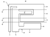
- FIG. 2 illustrates a representation of the configuration of the antenna of an embodiment of the present invention.
- FIG. 3 illustrates a representation of the antenna shown in FIG. 2 , here in which the antenna is configured with folds formed in the folded patch portion thereof.
- FIG. 4 illustrates a representation of an exemplary return loss, plotted as a function of frequency, of an exemplary antenna of an embodiment of the present invention.
- FIGS. 5 and 6 represent exemplary radiation patterns exhibited by the antenna of an embodiment of the present invention at two separate frequencies, at 950 MHz and 1880 MHz, respectively.
- FIG. 7 illustrates a method flow diagram representative of method of operation of an embodiment of the present invention.
- the present invention accordingly, advantageously provides an antenna, and an associated methodology for transducing signal energy at a radio device, such as a portable mobile station.
- an antenna is provided for the radio device.
- the antenna is of compact dimensions that permits its positioning within, or carriage together with, a mobile station.
- the antenna characteristics of the antenna permit its operation at selected frequency bands over a wide range of frequencies.
- the antenna includes a set of antenna patches that are configured together in a tri-dimensional arrangement that extends in multiple planar directions. Reduction in the spatial requirements of the antenna is provided by the tri-dimensional configuration of the antenna. One of the patches of the set of antenna patches is forwarded such that contiguous portions thereof extend in planar directions offset from that of a portion contiguous thereto.
- the antenna is configured to be operable at disparate frequency bands over a wide range of frequencies.
- a first patch of the antenna forms a first main radiation element.
- the first patch is L-shaped, forming an L-shaped patch.
- the first radiation element is resonant at a frequency band depending upon the length of the patch and its location of connection to the second patch of the antenna.
- the first main radiation element forming the L-shaped patch includes both a feed point connection and a ground connection that are connectable with corresponding portions of the circuitry of the mobile station. Signal energy generated at the mobile station circuitry is provided to the antenna at the feed point connection, and signal energy transduced into electrical form at the antenna is provided to the transceiver circuitry at the feed point connection.
- the L-shaped patch includes a lengthwise-extending leg piece and a foot piece extending outwardly therefrom. Appropriate selection of the dimensions of the leg piece and of the foot piece are determinative, together with the location of the connection of the L-shaped patch with the second antenna patch, of the characteristics of the first antenna patch.
- the second antenna patch forms a folded patch, formed of multiple folded portions.
- a first portion is contiguous to, and integral with, the L-shaped patch forming the first antenna patch.
- the first portion is folded to extend in a planar direction offset from that of the planar direction in which the L-shaped first antenna patch extends.
- the first folded portion of the folded antenna patch extends, e.g., in a planar direction substantially perpendicular to the planar direction in which the L-shaped, first antenna patch extends.
- the folded antenna patch further includes a second folded portion, formed contiguous to, and integral with, the first folded portion.
- the second folded portion is folded to extend in a direction offset from the planar direction in which the first folded section extends.
- the second folded portion extends in a direction, e.g., substantially perpendicular to the planar direction in which the first folded portion extends.
- the folded antenna patch further includes a third folded portion, formed contiguous to and integral with the second folded portion.
- the third folded portion extends, e.g., in a direction substantially perpendicular to the planar direction in which the second folded portion extends.
- the folded, second antenna patch includes a tuning strip, tunable to be of a length to cause the antenna patch to include resonant frequencies at a desired frequency range.
- the antenna forms a pent-band antenna, capable of operation at five disparate frequency bands, including the 850, 900, 1800, 1900, and 2200 MHz frequency bands.
- the antenna is configured to be resonant at other, and other numbers of, frequency bands.
- the antenna permits signal energy to be transduced at any of the resonant frequencies. Due to its compact size, the antenna facilitates increased miniaturization of a mobile station, permitting its positioning within the housing of the mobile station.
- a first patch forms a first radiation element.
- the first patch is defined in a first planar direction and is resonant at least at a first higher frequency band.
- a second patch forms a second resonant element.
- the second patch includes a contiguous first portion, contiguous and integral with, the first patch.
- the contiguous first portion is folded to be upstanding beyond the first planar direction in which the first patch extends. Thereby, the contiguous first portion extends in a second planar direction.
- the second patch is resonant at a lower frequency band and a second higher frequency band.
- the first and second higher frequency bands are, e g., of corresponding, overlapping, or differing frequencies.
- a radio communication system shown generally at 10 , provides for communication services, with mobile stations, of which the mobile station 12 is representative, by way of radio links defined upon a radio air interface 14 .
- the mobile station is generally representative of a mobile station operable in conformity with operating protocols of any of various operating specifications, in the exemplary implementation, the mobile station is operable to communicate at the 850, 900, 1800, 1900, and 2200 MHz frequency bands that correspond to 4 GSM (Global System for Mobile communications) frequency bands and a UMTS (Universal Mobile Telephone Service) band.
- GSM Global System for Mobile communications
- UMTS Universal Mobile Telephone Service
- a plurality of radio access networks (RANs), radio access networks 16 , 18 , 22 , 24 , and 26 are illustrated in FIG. 1 .
- the radio access networks 16 - 26 are representative, respectively, of a GSM 850 MHz system, a GSM 900 MHz system, a GSM 1800 MHz system, a GSM 1900 MHz system, and a UMTS 2200 MHz network, respectively.
- the mobile station 12 is positioned within the coverage area of any of such networks 16 - 26 , the mobile station is capable of communicating with the radio access network.
- the mobile station is positioned within the coverage of each of the radio access networks. That is to say, in the illustrated example, all of the networks have overlapping coverage areas.
- the radio access networks 16 - 26 are coupled, here by way of gateways (GWYs) 28 to a core network 30 .
- GWYs gateways
- a communication endpoint (CE) 32 is coupled to the core network.
- the communication endpoint is representative of a communication device that communicates with the mobile station.
- Transceiver circuitry 36 is embodied at the mobile station, formed of a transmit part and a receive part to operate upon data that is to be communicated by the mobile station or data that is received thereat.
- the receive and transmit chains forming the receive and transmit parts, respectively, of the transceiver circuitry are operable in conformity with the operating standards and protocols associated with, and defining, the respective systems.
- the transceiver circuitry of the mobile station is coupled to an antenna 42 of an embodiment of the present invention.
- the antenna is constructed to permit its operation to transduce signal energy at all of the frequency bands at which the mobile station transceiver circuitry is operable.
- the antenna 42 operates to transduce signal energy at any of the 850, 900, 1800, 1900, and 2200 MHz frequency bands.
- the antenna is positioned within the housing 44 of the mobile station to be supportively enclosed by the housing. Howsoever positioned, the antenna is of small dimensions, facilitating its carriage together with the mobile station at any of the frequencies at which the mobile station operates.
- FIG. 2 illustrates the antenna 42 , shown in FIG. 1 to form part of the mobile station 12 .
- the exemplary implementation shown in FIG. 2 forms a pent-band, i.e., a five-band, antenna that operates in conjunction with a five-band mobile station to transduce signal energy during its operation.
- the view shown in FIG. 2 is representative of the antenna prior to configuration into a tri-dimensional form. The view is that of the pattern of the antenna.
- the antenna is folded at folds 48 , 52 , and 54 , as shall be described below.
- the antenna is shaped into three dimensions to be tri-dimensional in shape.
- the resultant form of the antenna is substantially rectangular.
- the antenna includes two antenna patches, a first antenna patch 58 and a second antenna patch 62 .
- the first antenna patch 58 here comprises an L-shaped patch including a lengthwise-extending leg part 64 and an outwardly-extending foot part 66 .
- An outer lengthwise dimension of the L-shaped patch extends in a linear direction along the entire length of the patch.
- An inner lengthwise dimension, also extending in the same linear direction, is of a length that extends to the foot part and is of a length, in part, dependent upon the positioning and configuration of the foot part.
- the first antenna patch is connected to the transceiver circuitry (shown in FIG. 1 ) of the mobile station at a feed point connection 72 and a ground connection 74 .
- the first antenna patch is resonant at a frequency band of frequencies determined by the characteristics of the antenna patch.
- the lengthwise dimension of the patch i.e., the length of the leg piece of the L-shaped patch together with the location of connection of the second antenna patch is, in significant part, determinative of the operable frequency band of the first antenna patch.
- the first antenna patch is configured to exhibit a resonant band of a relatively high frequency.
- the second antenna patch 62 forms a folded patch with three portions, a first portion 78 , a second portion 82 , and a third portion 84 defined by the folding lines 48 , 52 , and 54 , respectively. That is to say, the portion 78 , 82 , and 84 are defined by the folding of the antenna patch at the fold lines.
- the first portion is constructed to be contiguous to, and integral with, portions of the first antenna patch 58 .
- the portion 78 When folded about the fold line 48 , the portion 78 extends in a second planar direction, offset from a first planar direction in which the first antenna patch extends.
- the planar directions are offset, e.g., by ninety degree angles to be perpendicular to one another.
- the second portion 82 is formed contiguous to, and integral with, the first portion 78 .
- Folding of the second portion about the fold line 52 causes the second portion to extend in a third planar direction, offset from the second planar direction in which the portion 78 extends.
- the angle formed by folding of the antenna patch about the fold line 54 forms a substantially perpendicular angle to cause the third portion to extend in a planar direction substantially perpendicular to the planar direction of the second portion.
- the three portions of the second antenna patch and the first antenna patch define four planar directions that, when perpendicular, together define a rectangular shape.
- the second portion 82 of the antenna patch 62 includes a tuning strip 88 that is of a length that is determinative of one of the frequency ranges, and hence bands, at which the antenna is resonant. And, the length of the patch, in the lengthwise direction, independently determines resonant frequencies at a lower frequency band and at a high frequency band. Tuning of the lower frequency is provided by the selection, or change, of the configuration of the tuning strip.
- FIG. 3 again illustrates the antenna 42 , shown previously in FIGS. 1 and 2 .
- the antenna is here positioned at a substrate 92 at which the transceiver circuitry 36 is mounted.
- the transceiver circuitry is connected by way of conductive paths 94 with the feed point connection and the ground connection 72 and 74 , respectively.
- the antenna is mounted upon a substrate part 98 that, in the exemplary implementation forms a FR-4 dielectric substrate of a thickness of 1.5 millimeters and is of a relative permittivity of 4.4. Folded as shown, the second portion 82 of the second antenna patch is upstanding beyond the first antenna patch 58 .
- the first portion 78 is of a height of 10 millimeters in the exemplary implementation.
- the ground panel size is 55 millimeters by 90 millimeters.
- the conductive paths of the first and second antenna patches of the antenna are of lengths and widths that are resonant at selected frequency ranges, selected in the exemplary implementation to be resonant at five frequency ranges, including the 850, 900, 1800, 1900, and 2200 MHz bands.
- a lower frequency band width extends between 824 and 961 MHz while a higher frequency band width extends from 1700 to 2200 MHz.
- Appropriate selection of the dimensions of the first antenna patch extends the bandwidth of the higher frequency band to extend between 1600 and 2300 MHz. Due to the folded nature of the second antenna patch, the space required on the substrate 92 / 98 is reduced relative to a two-dimensional implementation.
- FIG. 4 illustrates a graphical representation 104 that shows exemplary return loss of an exemplary antenna 42 shown in any of the preceding figures.
- Review of the representation illustrates pass bands 106 , 108 , and 112 .
- the pass bands are located at other frequencies.
- FIGS. 5 and 6 illustrate exemplary radiation patterns exhibited by the antenna 42 in an exemplary implementation.
- a first plot 118 is representative of the radiation pattern at 950 MHz in the YZ plane.
- the curve 122 is representative of a second radiation pattern, also at the 950 MHz frequency, but in an XY plane.
- a first radiation pattern 128 is representative of the radiation pattern at 1880 MHz in the YZ plane.
- the radiation pattern 132 is representative of the radiation pattern, at the same frequency, but in the XY plane.
- FIG. 7 illustrates a method flow diagram shown generally at 142 , representative of the method of operation of an embodiment of the present invention.
- the method transuces signal energy at a radio device.
- a first radiation element is formed, comprised of a first patch defined to extend in a first planar direction and resonant at a first frequency band.
- a second radiation element is formed.
- the second radiation element includes a folded loop having a contiguous first portion.
- the contiguous first portion is contiguous and integral with the first patch.
- the second radiation element also includes a contiguous second portion, contiguous and integral with the first portion.
- the contiguous first portion is folded to be upstanding beyond the first patch in a second planar direction and the contiguous second portion is folded to extend in a third planar direction, offset from the second planar direction.
- the second radiation element is resonant at a second frequency band.
- the second radiation element further includes a contiguous third portion, contiguous and integral with the contiguous second portion.
- the contiguous third portion extends in a fourth planar direction, offset from the third planar direction.
- the element is formed such that the second and fourth planar directions are substantially parallel and such that the third planar direction is substantially parallel to the first planar direction in which the first element extends.
- the folded loop is tuned.
- signal energy is transduced within any of the first and second frequency bands at any of the first patch and the folded loop.
- a multi-band antenna is formed, of compact configuration, facilitating its use together with a mobile station, or other portable radio device.
Abstract
Description
Claims (32)
Priority Applications (1)
| Application Number | Priority Date | Filing Date | Title |
|---|---|---|---|
| US11/843,802 US7719470B2 (en) | 2007-08-23 | 2007-08-23 | Multi-band antenna, and associated methodology, for a radio communication device |
Applications Claiming Priority (1)
| Application Number | Priority Date | Filing Date | Title |
|---|---|---|---|
| US11/843,802 US7719470B2 (en) | 2007-08-23 | 2007-08-23 | Multi-band antenna, and associated methodology, for a radio communication device |
Publications (2)
| Publication Number | Publication Date |
|---|---|
| US20090051595A1 US20090051595A1 (en) | 2009-02-26 |
| US7719470B2 true US7719470B2 (en) | 2010-05-18 |
Family
ID=40381659
Family Applications (1)
| Application Number | Title | Priority Date | Filing Date |
|---|---|---|---|
| US11/843,802 Active 2028-07-08 US7719470B2 (en) | 2007-08-23 | 2007-08-23 | Multi-band antenna, and associated methodology, for a radio communication device |
Country Status (1)
| Country | Link |
|---|---|
| US (1) | US7719470B2 (en) |
Cited By (7)
| Publication number | Priority date | Publication date | Assignee | Title |
|---|---|---|---|---|
| US20110043408A1 (en) * | 2009-08-20 | 2011-02-24 | Qualcomm Incorporated | Compact multi-band planar inverted f antenna |
| US8593367B2 (en) | 2010-12-10 | 2013-11-26 | Blackberry Limited | Modified ground plane (MGP) approach to improving antenna self-matching and bandwidth |
| US20150061939A1 (en) * | 2013-09-03 | 2015-03-05 | Wistron Corporation | Multi-band antenna and portable electronic device thereof |
| US9178283B1 (en) * | 2012-09-17 | 2015-11-03 | Amazon Technologies, Inc. | Quad-slot antenna for dual band operation |
| US9196966B1 (en) * | 2012-09-17 | 2015-11-24 | Amazon Technologies, Inc. | Quad-slot antenna for dual band operation |
| US9257750B2 (en) | 2013-05-15 | 2016-02-09 | Apple Inc. | Electronic device with multiband antenna |
| US20170018845A1 (en) * | 2015-07-17 | 2017-01-19 | Samsung Electro-Mechanics Co., Ltd. | Antenna apparatus |
Families Citing this family (12)
| Publication number | Priority date | Publication date | Assignee | Title |
|---|---|---|---|---|
| US8406825B2 (en) * | 2009-07-31 | 2013-03-26 | Research In Motion Limited | Integrated antenna and electrostatic discharge protection |
| US8386875B2 (en) | 2009-08-07 | 2013-02-26 | Research In Motion Limited | Method and system for handling HARQ operations during transmission mode changes |
| US8477069B2 (en) * | 2009-08-21 | 2013-07-02 | Mediatek Inc,. | Portable electronic device and antenna thereof |
| EP2323217B1 (en) * | 2009-11-13 | 2014-04-30 | BlackBerry Limited | Antenna for multi mode mimo communication in handheld devices |
| US8754814B2 (en) * | 2009-11-13 | 2014-06-17 | Blackberry Limited | Antenna for multi mode MIMO communication in handheld devices |
| CN104979623B (en) * | 2014-04-10 | 2018-05-08 | 深圳市六二九科技有限公司 | Collect the multifrequency antenna and wireless communication terminal of wireless telecommunications, data transfer and positioning |
| USD754108S1 (en) * | 2014-10-29 | 2016-04-19 | Airgain, Inc. | Antenna |
| USD883962S1 (en) | 2017-04-25 | 2020-05-12 | The Antenna Company International N.V. | Dual port antenna assembly |
| NL2019365B1 (en) * | 2017-07-28 | 2019-02-18 | The Antenna Company International N V | Component for a dual band antenna, a dual band antenna comprising said component, and a dual band antenna system. |
| US10985455B2 (en) | 2017-04-25 | 2021-04-20 | The Antenna Company International N.V. | EBG structure, EBG component, and antenna device |
| USD856313S1 (en) | 2017-04-25 | 2019-08-13 | The Antenna Company International N.V. | Dual port antenna |
| DE102019213127A1 (en) * | 2018-08-31 | 2020-03-05 | Mando Corporation | DEVICE FOR A NON-CONTACTIVE SENSOR WITH ESD PROTECTION STRUCTURE |
Citations (9)
| Publication number | Priority date | Publication date | Assignee | Title |
|---|---|---|---|---|
| WO2002035652A1 (en) | 2000-10-05 | 2002-05-02 | Ace Technology | Internal antennas for portable terminals and mounting method thereof |
| US20020075190A1 (en) | 2000-10-09 | 2002-06-20 | Indra Ghosh | Multiband microwave antenna |
| US20030142022A1 (en) | 2002-01-28 | 2003-07-31 | Nokia Corporation | Tunable patch antenna for wireless communication terminals |
| WO2004008573A1 (en) | 2002-07-15 | 2004-01-22 | Kathrein-Werke Kg | Low-height dual or multi-band antenna, in particular for motor vehicles |
| US6734825B1 (en) * | 2002-10-28 | 2004-05-11 | The National University Of Singapore | Miniature built-in multiple frequency band antenna |
| US6933893B2 (en) * | 2002-12-27 | 2005-08-23 | Motorola, Inc. | Electronically tunable planar antenna and method of tuning the same |
| US6982675B2 (en) * | 2003-12-13 | 2006-01-03 | Information And Communications University Educational Foundation | Internal multi-band antenna with multiple layers |
| US7079079B2 (en) * | 2004-06-30 | 2006-07-18 | Skycross, Inc. | Low profile compact multi-band meanderline loaded antenna |
| US20070001906A1 (en) * | 2003-05-16 | 2007-01-04 | Heiko Pelzer | Switchable multiband antenna for the high-frequency and microwave range |
-
2007
- 2007-08-23 US US11/843,802 patent/US7719470B2/en active Active
Patent Citations (9)
| Publication number | Priority date | Publication date | Assignee | Title |
|---|---|---|---|---|
| WO2002035652A1 (en) | 2000-10-05 | 2002-05-02 | Ace Technology | Internal antennas for portable terminals and mounting method thereof |
| US20020075190A1 (en) | 2000-10-09 | 2002-06-20 | Indra Ghosh | Multiband microwave antenna |
| US20030142022A1 (en) | 2002-01-28 | 2003-07-31 | Nokia Corporation | Tunable patch antenna for wireless communication terminals |
| WO2004008573A1 (en) | 2002-07-15 | 2004-01-22 | Kathrein-Werke Kg | Low-height dual or multi-band antenna, in particular for motor vehicles |
| US6734825B1 (en) * | 2002-10-28 | 2004-05-11 | The National University Of Singapore | Miniature built-in multiple frequency band antenna |
| US6933893B2 (en) * | 2002-12-27 | 2005-08-23 | Motorola, Inc. | Electronically tunable planar antenna and method of tuning the same |
| US20070001906A1 (en) * | 2003-05-16 | 2007-01-04 | Heiko Pelzer | Switchable multiband antenna for the high-frequency and microwave range |
| US6982675B2 (en) * | 2003-12-13 | 2006-01-03 | Information And Communications University Educational Foundation | Internal multi-band antenna with multiple layers |
| US7079079B2 (en) * | 2004-06-30 | 2006-07-18 | Skycross, Inc. | Low profile compact multi-band meanderline loaded antenna |
Cited By (9)
| Publication number | Priority date | Publication date | Assignee | Title |
|---|---|---|---|---|
| US20110043408A1 (en) * | 2009-08-20 | 2011-02-24 | Qualcomm Incorporated | Compact multi-band planar inverted f antenna |
| US9136594B2 (en) * | 2009-08-20 | 2015-09-15 | Qualcomm Incorporated | Compact multi-band planar inverted F antenna |
| US8593367B2 (en) | 2010-12-10 | 2013-11-26 | Blackberry Limited | Modified ground plane (MGP) approach to improving antenna self-matching and bandwidth |
| US9178283B1 (en) * | 2012-09-17 | 2015-11-03 | Amazon Technologies, Inc. | Quad-slot antenna for dual band operation |
| US9196966B1 (en) * | 2012-09-17 | 2015-11-24 | Amazon Technologies, Inc. | Quad-slot antenna for dual band operation |
| US9257750B2 (en) | 2013-05-15 | 2016-02-09 | Apple Inc. | Electronic device with multiband antenna |
| US20150061939A1 (en) * | 2013-09-03 | 2015-03-05 | Wistron Corporation | Multi-band antenna and portable electronic device thereof |
| US9203152B2 (en) * | 2013-09-03 | 2015-12-01 | Wistron Corporation | Multi-band antenna and portable electronic device thereof |
| US20170018845A1 (en) * | 2015-07-17 | 2017-01-19 | Samsung Electro-Mechanics Co., Ltd. | Antenna apparatus |
Also Published As
| Publication number | Publication date |
|---|---|
| US20090051595A1 (en) | 2009-02-26 |
Similar Documents
| Publication | Publication Date | Title |
|---|---|---|
| US7719470B2 (en) | Multi-band antenna, and associated methodology, for a radio communication device | |
| US9406998B2 (en) | Distributed multiband antenna and methods | |
| EP1869726B1 (en) | An antenna having a plurality of resonant frequencies | |
| US7629932B2 (en) | Antenna apparatus, and associated methodology, for a multi-band radio device | |
| JP4769793B2 (en) | Multi-band compact PIFA antenna with greatly bent slots | |
| US7450072B2 (en) | Modified inverted-F antenna for wireless communication | |
| EP1973192B1 (en) | Antenne apparatus and associated methodology for a multi-band radio device | |
| US7403161B2 (en) | Multiband antenna in a communication device | |
| US20030103010A1 (en) | Dual-band antenna arrangement | |
| US20120249384A1 (en) | Antenna arrangement and a portable radio communication device comprising such an antenna arrangement | |
| JP2006527557A (en) | Loop type multi-branch planar antenna having a plurality of resonance frequency bands and wireless terminal incorporating the same | |
| US7629933B2 (en) | Multi-band antenna, and associated methodology, for a radio communication device | |
| JP2008503972A (en) | Multi-band built-in antenna capable of independently adjusting resonance frequency and method for adjusting resonance frequency thereof | |
| CN112689033B (en) | Terminal device | |
| CN101682104A (en) | An antenna arrangement | |
| EP2028720B1 (en) | Multi-band antenna, and associated methodology, for a radio communication device | |
| JP2009111959A (en) | Parallel 2-wire antenna and wireless communication device | |
| Gummalla et al. | Compact metamaterial quad-band antenna for mobile application | |
| TWI719837B (en) | Tunable antenna module | |
| CN111725609B (en) | Antenna structure | |
| EP2028718B1 (en) | Multi-band antenna, and associated methodology, for a radio communication device | |
| CN107394348B (en) | Antenna assembly and mobile terminal | |
| CN113328238A (en) | Adjustable antenna module | |
| KR101245731B1 (en) | Multiband antenna |
Legal Events
| Date | Code | Title | Description |
|---|---|---|---|
| AS | Assignment |
Owner name: RESEARCH IN MOTION LIMITED, CANADA Free format text: ASSIGNMENT OF ASSIGNORS INTEREST;ASSIGNORS:WANG, DONG;WEN, GEYI;RAO, QINJIANG;AND OTHERS;REEL/FRAME:019737/0292 Effective date: 20070820 Owner name: RESEARCH IN MOTION LIMITED,CANADA Free format text: ASSIGNMENT OF ASSIGNORS INTEREST;ASSIGNORS:WANG, DONG;WEN, GEYI;RAO, QINJIANG;AND OTHERS;REEL/FRAME:019737/0292 Effective date: 20070820 |
|
| STCF | Information on status: patent grant |
Free format text: PATENTED CASE |
|
| FPAY | Fee payment |
Year of fee payment: 4 |
|
| AS | Assignment |
Owner name: BLACKBERRY LIMITED, ONTARIO Free format text: CHANGE OF NAME;ASSIGNOR:RESEARCH IN MOTION LIMITED;REEL/FRAME:032459/0207 Effective date: 20130709 |
|
| MAFP | Maintenance fee payment |
Free format text: PAYMENT OF MAINTENANCE FEE, 8TH YEAR, LARGE ENTITY (ORIGINAL EVENT CODE: M1552) Year of fee payment: 8 |
|
| MAFP | Maintenance fee payment |
Free format text: PAYMENT OF MAINTENANCE FEE, 12TH YEAR, LARGE ENTITY (ORIGINAL EVENT CODE: M1553); ENTITY STATUS OF PATENT OWNER: LARGE ENTITY Year of fee payment: 12 |
|
| AS | Assignment |
Owner name: MALIKIE INNOVATIONS LIMITED, IRELAND Free format text: ASSIGNMENT OF ASSIGNORS INTEREST;ASSIGNOR:BLACKBERRY LIMITED;REEL/FRAME:064104/0103 Effective date: 20230511 |
|
| AS | Assignment |
Owner name: MALIKIE INNOVATIONS LIMITED, IRELAND Free format text: NUNC PRO TUNC ASSIGNMENT;ASSIGNOR:BLACKBERRY LIMITED;REEL/FRAME:064270/0001 Effective date: 20230511 |