US7717361B2 - Distributor plate with diffuser on fixed shaft - Google Patents
Distributor plate with diffuser on fixed shaft Download PDFInfo
- Publication number
- US7717361B2 US7717361B2 US11/513,014 US51301406A US7717361B2 US 7717361 B2 US7717361 B2 US 7717361B2 US 51301406 A US51301406 A US 51301406A US 7717361 B2 US7717361 B2 US 7717361B2
- Authority
- US
- United States
- Prior art keywords
- plate
- shaft
- water distribution
- diffuser
- bearings
- Prior art date
- Legal status (The legal status is an assumption and is not a legal conclusion. Google has not performed a legal analysis and makes no representation as to the accuracy of the status listed.)
- Expired - Fee Related, expires
Links
Images



Classifications
-
- B—PERFORMING OPERATIONS; TRANSPORTING
- B05—SPRAYING OR ATOMISING IN GENERAL; APPLYING FLUENT MATERIALS TO SURFACES, IN GENERAL
- B05B—SPRAYING APPARATUS; ATOMISING APPARATUS; NOZZLES
- B05B3/00—Spraying or sprinkling apparatus with moving outlet elements or moving deflecting elements
- B05B3/02—Spraying or sprinkling apparatus with moving outlet elements or moving deflecting elements with rotating elements
- B05B3/04—Spraying or sprinkling apparatus with moving outlet elements or moving deflecting elements with rotating elements driven by the liquid or other fluent material discharged, e.g. the liquid actuating a motor before passing to the outlet
- B05B3/0417—Spraying or sprinkling apparatus with moving outlet elements or moving deflecting elements with rotating elements driven by the liquid or other fluent material discharged, e.g. the liquid actuating a motor before passing to the outlet comprising a liquid driven rotor, e.g. a turbine
- B05B3/0425—Spraying or sprinkling apparatus with moving outlet elements or moving deflecting elements with rotating elements driven by the liquid or other fluent material discharged, e.g. the liquid actuating a motor before passing to the outlet comprising a liquid driven rotor, e.g. a turbine actuated downstream of the outlet elements
- B05B3/0426—Spraying or sprinkling apparatus with moving outlet elements or moving deflecting elements with rotating elements driven by the liquid or other fluent material discharged, e.g. the liquid actuating a motor before passing to the outlet comprising a liquid driven rotor, e.g. a turbine actuated downstream of the outlet elements the liquid driven rotor being a deflecting rotating element
-
- B—PERFORMING OPERATIONS; TRANSPORTING
- B05—SPRAYING OR ATOMISING IN GENERAL; APPLYING FLUENT MATERIALS TO SURFACES, IN GENERAL
- B05B—SPRAYING APPARATUS; ATOMISING APPARATUS; NOZZLES
- B05B3/00—Spraying or sprinkling apparatus with moving outlet elements or moving deflecting elements
- B05B3/003—Spraying or sprinkling apparatus with moving outlet elements or moving deflecting elements with braking means, e.g. friction rings designed to provide a substantially constant revolution speed
-
- B—PERFORMING OPERATIONS; TRANSPORTING
- B05—SPRAYING OR ATOMISING IN GENERAL; APPLYING FLUENT MATERIALS TO SURFACES, IN GENERAL
- B05B—SPRAYING APPARATUS; ATOMISING APPARATUS; NOZZLES
- B05B3/00—Spraying or sprinkling apparatus with moving outlet elements or moving deflecting elements
- B05B3/003—Spraying or sprinkling apparatus with moving outlet elements or moving deflecting elements with braking means, e.g. friction rings designed to provide a substantially constant revolution speed
- B05B3/005—Spraying or sprinkling apparatus with moving outlet elements or moving deflecting elements with braking means, e.g. friction rings designed to provide a substantially constant revolution speed using viscous dissipation, e.g. a rotor movable in a chamber filled with oil
Definitions
- a water distribution plate and a stream diffuser plate are both mounted for rotation on a single, fixed shaft.
- the water distribution and diffuser plates rotate independently of one another, however, and both are viscously braked to slow the rate of rotation of the plates.
- a shaft extends upwardly through the nozzle of a sprinkler head or body and supports the water distribution plate and diffuser plate downstream of an arcuate or full circle stream emitted from the nozzle.
- the water distribution plate is generally cone-shaped and formed with a plurality of grooves that are slightly curved in a circumferential direction so that the stream impinging on the grooves causes the plate to rotate about the shaft.
- a first stator component is fixed to the shaft and located within a sealed chamber in the water distribution plate, the chamber at least partially filled with a viscous fluid that causes the rate of rotation of the water distribution plate to be significantly slowed in comparison to an unbraked rate of rotation.
- the diffuser plate Downstream of the water distribution plate, the diffuser plate is mounted on the shaft in a similar manner, with a second sealed stator element fixed to the shaft in a chamber at least partially filled with viscous fluid.
- the diffuser plate is provided with a plurality of diffuser elements projecting downwardly from a peripheral edge of the lower surface of the diffuser.
- the water distribution plate rotates at a specific and substantially constant speed, while the diffuser plate rotates at an intermittent and random speed.
- the diffuser plate is designed such that when one or more stream components from the water distribution plate impinges on a diffuser element, the stream components break up to fill in the wetted pattern area while at the same time, the diffuser element is driven to a new and random position.
- the diffuser elements are provided with curved vane surfaces that cause the diffuser plate to rotate when struck by stream components emitted from the water distribution plate.
- the water distribution plate and diffuser plate are again mounted on a single shaft, but the shaft is supported within a cap assembly that is in turn supported on the sprinkler body downstream of the nozzle.
- the shaft does not project upwardly through the sprinkler nozzle.
- the mounting of the water distribution plate and diffuser plate on the single fixed shaft, and the viscous damping arrangement remains substantially as described hereinabove.
- the invention relates to a water distribution plate and diffuser plate assembly for distributing a stream emitted from a sprinkler nozzle comprising: a shaft having one end attached to a sprinkler component and an opposite end supporting first and second plates in axially spaced relationship for rotation about the shaft independent of one another; the first plate located adjacent the nozzle and formed with at least one water distribution groove shaped and arranged to divide a primary stream emitted from the nozzle into a plurality of secondary streams, and the second plate located downstream of the first plate and formed with at least one diffuser element arranged to be struck by at least some of the secondary streams exiting the first plate, and wherein speed of rotation of the first and second plates is braked.
- the invention in another aspect, relates to a water distribution plate and diffuser plate assembly for distributing a stream emitted from a sprinkler nozzle comprising: a shaft having one end attached to a sprinkler component and an opposite end supporting first and second plates in axially spaced relationship for rotation about the shaft independent of one another; the first plate located adjacent the nozzle and formed with at least one water distribution groove shaped and arranged to divide a primary stream emitted from the nozzle into a plurality of secondary streams, and the second plate located downstream of the first plate and formed with at least one diffuser element arranged to be struck by at least some of the secondary streams exiting the first plate; the first plate formed with a first internal chamber, with a first stator element secured to the shaft and received in the first internal chamber, the second plate formed with a second internal chamber, with a second stator element secured to the shaft and received in the second internal chamber, the first and second internal chambers at least partially filled with a viscous fluid.
- FIG. 1 is a partial cross section through a rotary sprinkler incorporating a water distribution plate and diffuser plate in accordance with a first exemplary embodiment of the invention
- FIG. 2 is a front elevation of a shaft provided with a pair of stator elements as incorporated in the sprinkler shown in FIG. 1 ;
- FIG. 3 is a sectioned perspective view of the water distribution and diffuser plates in accordance with the first exemplary embodiment of the invention
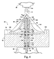
- FIG. 4 is a partial cross section through a rotary sprinkler in accordance with a second exemplary embodiment of the invention.
- FIG. 5 is a sectioned perspective view of the water distribution plate and diffuser plate shown in FIG. 4 .
- a sprinkler head is partially shown at 10 , the sprinkler head incorporating a nozzle 12 and supporting one end of a shaft 14 .
- the shaft 14 (see also FIGS. 2 and 3 ) extends out of the sprinkler head, in a downstream direction, and supports a water distribution plate and diffuser assembly 16 for impingement by a stream S emitted from the nozzle.
- a stream deflector 18 is fixed to the shaft 14 and cooperates to define the nozzle orifice 20 .
- the deflector guides an arcuate (or round) stream onto the water distribution plate 22 for redirecting the water in a substantially radially outward direction as described further herein.
- the water distribution plate 22 is formed with at least one, but in this embodiment with a plurality of grooves 24 shaped to divide a single vertically-oriented arcuate or full 360° stream (or multi-streams) emitted from the nozzle 12 into a plurality of secondary streams or stream components, and to redirect those stream components in a generally radial direction.
- Grooves 24 are also curved slightly in a circumferential direction such that the water distribution plate 22 is caused to rotate about the shaft 14 as a result of the plurality of stream components acting on the interior walls of the grooves.
- Such water distribution plates are well-known in the art.
- the water distribution plate 22 is also bored and counterbored to receive the shaft 14 and to support a pair of shaft bearings 26 , 28 within cavities 30 , 32 on either side or end of a smaller diameter center chamber 34 .
- Flexible lip seals 36 , 38 are seated on shoulders 40 , 42 , respectively, in the bearings, with annular retainers 44 , 46 press-fit into the cavities to hold the seals in place.
- shaft 14 passes through the bearings, seals and retainers, and the distribution plate rotates relative to the shaft.
- a first disk-like stator 48 is fixed to the shaft 14 at a location where it will be centered within the chamber 34 .
- the latter is at least partially filled with a viscous fluid (such as a silicone grease), with seals 36 , 38 preventing escape of the viscous fluid in opposite directions along the shaft.
- Rotation of the distribution plate 22 is slowed by the viscous shearing of the fluid as the plate rotates relative to the fixed stator 48 .
- the diffuser 50 includes a substantially solid, cylindrical body 52 , with at least one, but in this embodiment a plurality of diffuser elements 54 projecting downwardly from a peripheral edge of the lower surface 56 of the body 52 .
- the diffuser elements 54 are circumferentially spaced about the lower peripheral edge of the body 52 , with uniform or nonuniform spaces therebetween.
- Each element 54 has a curved vane surface 58 (best seen in FIG. 3 ) that is arranged to interrupt stream components emanating from the grooves 24 in the water distribution plate, and to drive the diffuser plate to a new position.
- the elements 54 are substantially laterally aligned with the upper ends of grooves 24 , but recognizing, however, that there are fewer elements 54 than grooves 24 .
- the manner in which the diffuser 50 is supported on the shaft 14 is generally similar to the manner in which the water distribution plate 22 is supported on the same shaft.
- the diffuser 50 is bored and counterbored to provide a pair of cavities 60 , 62 on either side of a second, smaller-diameter chamber 64 .
- the cavities 60 , 62 accommodate a second pair of shaft bearings 66 , 68 on opposite sides of the center cavity and flexible lip seals 70 , 72 are seated on shoulders 74 , 76 , formed respectively, on the bearings.
- Retainers 78 , 80 hold the respective seals in place.
- a second, substantially cylindrical stator 82 is fixed to the shaft 14 so as to be centered within the second chamber 64 .
- a similar viscous fluid fills at least part of the chamber, with seals 70 , 72 preventing leakage along the shaft. In this way, the rotation of the diffuser plate is also viscously damped or slowed by viscous shearing in the chamber 64 .
- the diffuser 50 will only move when stream components from the water distribution plate grooves 24 strike a vane surface 58 of a diffuser element 54 causing the diffuser 50 to rotate to a different position.
- the stator 82 is sized to provide enough braking of the diffuser 50 to ensure that it rotates slower than plate 22 . Since the number of diffuser-elements is less than the number of grooves in the water distribution plate 22 , not all secondary streams leaving the water distribution plate are diffused, and thus the diffuser plate will rotate intermittently to random positions, thus enhancing uniformity of the wetted pattern area.
- stator elements 48 , 82 are designed so that with compression loads, the two bearings on either side of these elements are pressed on either side to allow little or no movement.
- the two plastic bearings also handle axial loading.
- FIGS. 4 and 5 A second embodiment of a combined water distribution plate/diffuser assembly 84 is shown in FIGS. 4 and 5 .
- a more sharply defined conically-shaped water distribution plate 86 is supported at one end 88 of a fixed shaft 90 .
- shaft end 88 terminates within the water distribution plate.
- a diffuser plate 92 provided with diffuser elements 94 is supported on the shaft 90 adjacent the water distribution plate, and the opposite end 96 of the shaft 90 is fixed within, for example, a cap assembly 98 that is typically supported above (or below) a sprinkler body 99 by one or more struts (not shown).
- a nozzle 100 emits a single solid stream S that is located upstream of the water distribution plate 86 , and the shaft 90 forms no part of, nor does it extend through, the nozzle supported in the sprinkler body.
- the water distribution plate 86 is formed with grooves 102 that redirect the stream and that cause the plate to rotate on the shaft, but here, the grooves continue to an apex 104 on which the solid stream S impinges and breaks up into secondary streams or stream components that flow through the grooves 102 , causing rotation of the plate 86 .
- the one end 88 of shaft 90 is received in a blind bore 106 formed in the plate 86 , with a thrust bearing 108 interposed between the shaft end and the end face 110 of the bore.
- the blind bore 106 is counterbored to form a cavity 112 that receives a first substantially cylindrical stator 114 , a shaft bearing 116 , flexible lip seal 118 and retainer 120 .
- a fluid chamber 122 is defined between end face 124 of the cavity 112 and the bearing 116 in which the stator 114 is located.
- the chamber is at least partially filled with a viscous fluid.
- the lip seal 118 seated on bearing shoulder 126 , prevents escape of the fluid along the shaft.
- the diffuser 92 is formed with a centerbore 128 through which the shaft 90 passes.
- the shaft also passes through a pair of shaft bearings 130 , 132 located in the bore 128 , defining a second fluid chamber 134 that receives a second substantially cylindrical stator 136 fixed to the shaft.
- the chamber 134 is at least partially filled with a viscous fluid, with leakage prevented by flexible lip seals 138 , 140 seated on respective shoulders 142 , 144 of the bearings 130 , 132 .
- Annular retainers 146 , 148 hold the seals and bearings in place.
- the main or primary solid stream S impinges on the grooves 102 , forming plural, fully developed secondary streams or stream components that exit the distributor (or first) plate 86 in radial directions.
- the speed of rotation of the plate 86 is desirably slowed by the shearing action between the silicone fluid in chamber 122 and the first stator 114 .
- the exact speed of rotation can be controlled by the viscosity of the fluid.
Landscapes
- Nozzles (AREA)
Priority Applications (3)
| Application Number | Priority Date | Filing Date | Title |
|---|---|---|---|
| US11/513,014 US7717361B2 (en) | 2006-08-31 | 2006-08-31 | Distributor plate with diffuser on fixed shaft |
| EP07253233A EP1894633A3 (de) | 2006-08-31 | 2007-08-16 | Verteilerplatte mit Diffusor auf verankertem Schaft |
| AU2007209838A AU2007209838B2 (en) | 2006-08-31 | 2007-08-20 | Distributor plate with diffuser on fixed shaft |
Applications Claiming Priority (1)
| Application Number | Priority Date | Filing Date | Title |
|---|---|---|---|
| US11/513,014 US7717361B2 (en) | 2006-08-31 | 2006-08-31 | Distributor plate with diffuser on fixed shaft |
Publications (2)
| Publication Number | Publication Date |
|---|---|
| US20080054094A1 US20080054094A1 (en) | 2008-03-06 |
| US7717361B2 true US7717361B2 (en) | 2010-05-18 |
Family
ID=38543602
Family Applications (1)
| Application Number | Title | Priority Date | Filing Date |
|---|---|---|---|
| US11/513,014 Expired - Fee Related US7717361B2 (en) | 2006-08-31 | 2006-08-31 | Distributor plate with diffuser on fixed shaft |
Country Status (3)
| Country | Link |
|---|---|
| US (1) | US7717361B2 (de) |
| EP (1) | EP1894633A3 (de) |
| AU (1) | AU2007209838B2 (de) |
Cited By (13)
| Publication number | Priority date | Publication date | Assignee | Title |
|---|---|---|---|---|
| US20100116301A1 (en) * | 2007-04-11 | 2010-05-13 | BSH Bosch und Siemens Hausgeräte GmbH | Top spray device for dishwashers |
| US8414662B2 (en) | 2007-09-07 | 2013-04-09 | Mansur Abahusayn | Salt brine capillary crystallization |
| US20140083470A1 (en) * | 2012-09-25 | 2014-03-27 | Daegyu KIM | Dishwashing machine |
| US20150102127A1 (en) * | 2013-10-10 | 2015-04-16 | General Electric Company | Spray assembly for a dishwasher appliance |
| US9492832B2 (en) | 2013-03-14 | 2016-11-15 | Rain Bird Corporation | Sprinkler with brake assembly |
| US9700904B2 (en) | 2014-02-07 | 2017-07-11 | Rain Bird Corporation | Sprinkler |
| US10322423B2 (en) | 2016-11-22 | 2019-06-18 | Rain Bird Corporation | Rotary nozzle |
| US10350619B2 (en) | 2013-02-08 | 2019-07-16 | Rain Bird Corporation | Rotary sprinkler |
| US11000866B2 (en) | 2019-01-09 | 2021-05-11 | Rain Bird Corporation | Rotary nozzles and deflectors |
| US11059056B2 (en) | 2019-02-28 | 2021-07-13 | Rain Bird Corporation | Rotary strip nozzles and deflectors |
| US11154877B2 (en) | 2017-03-29 | 2021-10-26 | Rain Bird Corporation | Rotary strip nozzles |
| US11406999B2 (en) | 2019-05-10 | 2022-08-09 | Rain Bird Corporation | Irrigation nozzle with one or more grit vents |
| US11511289B2 (en) | 2017-07-13 | 2022-11-29 | Rain Bird Corporation | Rotary full circle nozzles and deflectors |
Families Citing this family (1)
| Publication number | Priority date | Publication date | Assignee | Title |
|---|---|---|---|---|
| US8567699B2 (en) * | 2009-08-05 | 2013-10-29 | Nelson Irrigation Corporation | Rotary strut sprinkler |
Citations (17)
| Publication number | Priority date | Publication date | Assignee | Title |
|---|---|---|---|---|
| US3727842A (en) | 1971-06-24 | 1973-04-17 | Toro Mfg Corp | Agricultural sprinkler head |
| US4375513A (en) | 1980-12-18 | 1983-03-01 | Eli Lilly And Company | Biologically pure culture of Actinoplanes missouriensis |
| US4836450A (en) | 1988-04-29 | 1989-06-06 | Hunter Edwin J | Sprinkler unit with alternating stream interruptor |
| US4836449A (en) | 1987-05-15 | 1989-06-06 | Hunter Edwin J | Sprinkler unit with stream deflector |
| EP0339966A2 (de) | 1988-04-29 | 1989-11-02 | Dan Mamtirim, Limited Partnership | Rotierende Berieselungsanlage |
| US4957240A (en) | 1987-10-01 | 1990-09-18 | Peretz Rosenberg | Rotary sprinklers |
| EP0518579A2 (de) | 1991-06-13 | 1992-12-16 | Harold D. Curtis | Automatisch einstellbarer Flüssigkeitsverteiler |
| US5192024A (en) | 1990-09-17 | 1993-03-09 | Blee Leonard J | Sprinkler |
| US5288022A (en) | 1991-11-08 | 1994-02-22 | Nelson Irrigation Corporation | Part circle rotator with improved nozzle assembly |
| US5372307A (en) | 1993-08-10 | 1994-12-13 | Nelson Irrigation Corporation | Rotary sprinkler stream interrupter |
| US5671886A (en) | 1995-08-23 | 1997-09-30 | Nelson Irrigation Corporation | Rotary sprinkler stream interrupter with enhanced emitting stream |
| US5718381A (en) * | 1994-08-24 | 1998-02-17 | Gardena Kress + Kastner Gmbh | Sprinkler for discharging a fluid |
| US20040050955A1 (en) | 2001-03-28 | 2004-03-18 | Nelson Irrigation Corporation | Adjustable arc, adjustable flow rate sprinkler |
| US20040195359A1 (en) | 2003-03-13 | 2004-10-07 | Curtis Harold D. | Fluid distributing apparatus |
| US6899287B2 (en) * | 2002-12-16 | 2005-05-31 | Senninger Irrigation Inc. | Rotary sprinkler |
| US7025287B2 (en) * | 2003-08-14 | 2006-04-11 | Nelson Irrigation Corporation | Shaft seal with grease retainer |
| US7395977B2 (en) * | 2004-11-22 | 2008-07-08 | Senninger Irrigation Inc. | Sprinkler apparatus |
Family Cites Families (1)
| Publication number | Priority date | Publication date | Assignee | Title |
|---|---|---|---|---|
| US4836540A (en) | 1988-05-24 | 1989-06-06 | Bean Jeffrey W | Rotating ring game |
-
2006
- 2006-08-31 US US11/513,014 patent/US7717361B2/en not_active Expired - Fee Related
-
2007
- 2007-08-16 EP EP07253233A patent/EP1894633A3/de not_active Withdrawn
- 2007-08-20 AU AU2007209838A patent/AU2007209838B2/en not_active Ceased
Patent Citations (18)
| Publication number | Priority date | Publication date | Assignee | Title |
|---|---|---|---|---|
| US3727842A (en) | 1971-06-24 | 1973-04-17 | Toro Mfg Corp | Agricultural sprinkler head |
| US4375513A (en) | 1980-12-18 | 1983-03-01 | Eli Lilly And Company | Biologically pure culture of Actinoplanes missouriensis |
| US4836449A (en) | 1987-05-15 | 1989-06-06 | Hunter Edwin J | Sprinkler unit with stream deflector |
| US4957240A (en) | 1987-10-01 | 1990-09-18 | Peretz Rosenberg | Rotary sprinklers |
| US4836450A (en) | 1988-04-29 | 1989-06-06 | Hunter Edwin J | Sprinkler unit with alternating stream interruptor |
| EP0339966A2 (de) | 1988-04-29 | 1989-11-02 | Dan Mamtirim, Limited Partnership | Rotierende Berieselungsanlage |
| US5192024A (en) | 1990-09-17 | 1993-03-09 | Blee Leonard J | Sprinkler |
| EP0518579A2 (de) | 1991-06-13 | 1992-12-16 | Harold D. Curtis | Automatisch einstellbarer Flüssigkeitsverteiler |
| US5288022A (en) | 1991-11-08 | 1994-02-22 | Nelson Irrigation Corporation | Part circle rotator with improved nozzle assembly |
| US5372307A (en) | 1993-08-10 | 1994-12-13 | Nelson Irrigation Corporation | Rotary sprinkler stream interrupter |
| US5718381A (en) * | 1994-08-24 | 1998-02-17 | Gardena Kress + Kastner Gmbh | Sprinkler for discharging a fluid |
| US5671886A (en) | 1995-08-23 | 1997-09-30 | Nelson Irrigation Corporation | Rotary sprinkler stream interrupter with enhanced emitting stream |
| US20040050955A1 (en) | 2001-03-28 | 2004-03-18 | Nelson Irrigation Corporation | Adjustable arc, adjustable flow rate sprinkler |
| US6899287B2 (en) * | 2002-12-16 | 2005-05-31 | Senninger Irrigation Inc. | Rotary sprinkler |
| US20040195359A1 (en) | 2003-03-13 | 2004-10-07 | Curtis Harold D. | Fluid distributing apparatus |
| US7025287B2 (en) * | 2003-08-14 | 2006-04-11 | Nelson Irrigation Corporation | Shaft seal with grease retainer |
| US7086608B2 (en) * | 2003-08-14 | 2006-08-08 | Nelson Irrigation Corporation | Shaft seal with grease retainer |
| US7395977B2 (en) * | 2004-11-22 | 2008-07-08 | Senninger Irrigation Inc. | Sprinkler apparatus |
Non-Patent Citations (1)
| Title |
|---|
| European Search Report dated Jul. 18, 2008 of Application No. EP 07 25 3233. |
Cited By (20)
| Publication number | Priority date | Publication date | Assignee | Title |
|---|---|---|---|---|
| US20100116301A1 (en) * | 2007-04-11 | 2010-05-13 | BSH Bosch und Siemens Hausgeräte GmbH | Top spray device for dishwashers |
| US8414662B2 (en) | 2007-09-07 | 2013-04-09 | Mansur Abahusayn | Salt brine capillary crystallization |
| US20140083470A1 (en) * | 2012-09-25 | 2014-03-27 | Daegyu KIM | Dishwashing machine |
| AU2013224750B2 (en) * | 2012-09-25 | 2016-04-14 | Lg Electronics Inc. | Dishwashing machine |
| US9936851B2 (en) * | 2012-09-25 | 2018-04-10 | Lg Electronics Inc. | Dishwashing machine |
| US10350619B2 (en) | 2013-02-08 | 2019-07-16 | Rain Bird Corporation | Rotary sprinkler |
| US11084051B2 (en) | 2013-02-08 | 2021-08-10 | Rain Bird Corporation | Sprinkler with brake assembly |
| US9492832B2 (en) | 2013-03-14 | 2016-11-15 | Rain Bird Corporation | Sprinkler with brake assembly |
| US20150102127A1 (en) * | 2013-10-10 | 2015-04-16 | General Electric Company | Spray assembly for a dishwasher appliance |
| US10507476B2 (en) | 2014-02-07 | 2019-12-17 | Rain Bird Corporation | Sprinkler with brake assembly |
| US9700904B2 (en) | 2014-02-07 | 2017-07-11 | Rain Bird Corporation | Sprinkler |
| US10322423B2 (en) | 2016-11-22 | 2019-06-18 | Rain Bird Corporation | Rotary nozzle |
| US11154881B2 (en) | 2016-11-22 | 2021-10-26 | Rain Bird Corporation | Rotary nozzle |
| US11154877B2 (en) | 2017-03-29 | 2021-10-26 | Rain Bird Corporation | Rotary strip nozzles |
| US11511289B2 (en) | 2017-07-13 | 2022-11-29 | Rain Bird Corporation | Rotary full circle nozzles and deflectors |
| US11666929B2 (en) | 2017-07-13 | 2023-06-06 | Rain Bird Corporation | Rotary full circle nozzles and deflectors |
| US11000866B2 (en) | 2019-01-09 | 2021-05-11 | Rain Bird Corporation | Rotary nozzles and deflectors |
| US11059056B2 (en) | 2019-02-28 | 2021-07-13 | Rain Bird Corporation | Rotary strip nozzles and deflectors |
| US11406999B2 (en) | 2019-05-10 | 2022-08-09 | Rain Bird Corporation | Irrigation nozzle with one or more grit vents |
| US12053791B2 (en) | 2019-05-10 | 2024-08-06 | Rain Bird Corporation | Irrigation nozzle with one or more grit vents |
Also Published As
| Publication number | Publication date |
|---|---|
| AU2007209838A1 (en) | 2008-03-20 |
| EP1894633A2 (de) | 2008-03-05 |
| AU2007209838B2 (en) | 2012-04-05 |
| US20080054094A1 (en) | 2008-03-06 |
| EP1894633A3 (de) | 2008-08-27 |
Similar Documents
| Publication | Publication Date | Title |
|---|---|---|
| AU2007209838B2 (en) | Distributor plate with diffuser on fixed shaft | |
| AU2007209840B2 (en) | Distributor plate and diffuser plate on sleeved shaft | |
| US7143957B2 (en) | Two-axis full-circle sprinkler with bent, rotating nozzle | |
| US7100842B2 (en) | Two-axis full-circle sprinkler | |
| US5671886A (en) | Rotary sprinkler stream interrupter with enhanced emitting stream | |
| US7240860B2 (en) | Water distribution plate for rotating sprinklers | |
| US7395977B2 (en) | Sprinkler apparatus | |
| EP1849526B1 (de) | Sprinkler mit viskosem Verzögerer | |
| US8991724B2 (en) | Wobbling sprinkler with viscous brake | |
| US6155494A (en) | Rotary nozzle device for emitting a water jet | |
| US8567691B2 (en) | Sprinkler with viscous hesitator and related method | |
| AU2017359302B2 (en) | Rotary nozzle sprinkler with orbital diffuser | |
| US7980488B2 (en) | Sprinkler with geared viscous hesitator and related method | |
| US7063274B2 (en) | Cleaning nozzle | |
| JPH09103713A (ja) | 回転散水器 | |
| JPS60257865A (ja) | スプレーチツプ | |
| US4957240A (en) | Rotary sprinklers | |
| CA2894292A1 (en) | Control valve | |
| AU4889200A (en) | Rotary atomisers |
Legal Events
| Date | Code | Title | Description |
|---|---|---|---|
| AS | Assignment |
Owner name: NELSON IRRIGATION CORPORATION, WASHINGTON Free format text: ASSIGNMENT OF ASSIGNORS INTEREST;ASSIGNORS:NELSON, CRAIG;SESSER, GEORGE L.;BARRY, PATRICK T.;REEL/FRAME:018256/0001;SIGNING DATES FROM 20060825 TO 20060828 Owner name: NELSON IRRIGATION CORPORATION,WASHINGTON Free format text: ASSIGNMENT OF ASSIGNORS INTEREST;ASSIGNORS:NELSON, CRAIG;SESSER, GEORGE L.;BARRY, PATRICK T.;SIGNING DATES FROM 20060825 TO 20060828;REEL/FRAME:018256/0001 |
|
| STCF | Information on status: patent grant |
Free format text: PATENTED CASE |
|
| FPAY | Fee payment |
Year of fee payment: 4 |
|
| MAFP | Maintenance fee payment |
Free format text: PAYMENT OF MAINTENANCE FEE, 8TH YR, SMALL ENTITY (ORIGINAL EVENT CODE: M2552) Year of fee payment: 8 |
|
| FEPP | Fee payment procedure |
Free format text: MAINTENANCE FEE REMINDER MAILED (ORIGINAL EVENT CODE: REM.); ENTITY STATUS OF PATENT OWNER: SMALL ENTITY |
|
| LAPS | Lapse for failure to pay maintenance fees |
Free format text: PATENT EXPIRED FOR FAILURE TO PAY MAINTENANCE FEES (ORIGINAL EVENT CODE: EXP.); ENTITY STATUS OF PATENT OWNER: SMALL ENTITY |
|
| STCH | Information on status: patent discontinuation |
Free format text: PATENT EXPIRED DUE TO NONPAYMENT OF MAINTENANCE FEES UNDER 37 CFR 1.362 |
|
| STCH | Information on status: patent discontinuation |
Free format text: PATENT EXPIRED DUE TO NONPAYMENT OF MAINTENANCE FEES UNDER 37 CFR 1.362 |
|
| FP | Lapsed due to failure to pay maintenance fee |
Effective date: 20220518 |