US7714460B2 - Electric steering lock device - Google Patents
Electric steering lock device Download PDFInfo
- Publication number
- US7714460B2 US7714460B2 US12/232,866 US23286608A US7714460B2 US 7714460 B2 US7714460 B2 US 7714460B2 US 23286608 A US23286608 A US 23286608A US 7714460 B2 US7714460 B2 US 7714460B2
- Authority
- US
- United States
- Prior art keywords
- electric motor
- status
- relay
- steering shaft
- pair
- Prior art date
- Legal status (The legal status is an assumption and is not a legal conclusion. Google has not performed a legal analysis and makes no representation as to the accuracy of the status listed.)
- Expired - Fee Related
Links
Images


Classifications
-
- B—PERFORMING OPERATIONS; TRANSPORTING
- B62—LAND VEHICLES FOR TRAVELLING OTHERWISE THAN ON RAILS
- B62D—MOTOR VEHICLES; TRAILERS
- B62D5/00—Power-assisted or power-driven steering
- B62D5/04—Power-assisted or power-driven steering electrical, e.g. using an electric servo-motor connected to, or forming part of, the steering gear
-
- B—PERFORMING OPERATIONS; TRANSPORTING
- B60—VEHICLES IN GENERAL
- B60R—VEHICLES, VEHICLE FITTINGS, OR VEHICLE PARTS, NOT OTHERWISE PROVIDED FOR
- B60R25/00—Fittings or systems for preventing or indicating unauthorised use or theft of vehicles
- B60R25/01—Fittings or systems for preventing or indicating unauthorised use or theft of vehicles operating on vehicle systems or fittings, e.g. on doors, seats or windscreens
- B60R25/02—Fittings or systems for preventing or indicating unauthorised use or theft of vehicles operating on vehicle systems or fittings, e.g. on doors, seats or windscreens operating on the steering mechanism
- B60R25/021—Fittings or systems for preventing or indicating unauthorised use or theft of vehicles operating on vehicle systems or fittings, e.g. on doors, seats or windscreens operating on the steering mechanism restraining movement of the steering column or steering wheel hub, e.g. restraining means controlled by ignition switch
- B60R25/0215—Fittings or systems for preventing or indicating unauthorised use or theft of vehicles operating on vehicle systems or fittings, e.g. on doors, seats or windscreens operating on the steering mechanism restraining movement of the steering column or steering wheel hub, e.g. restraining means controlled by ignition switch using electric means, e.g. electric motors or solenoids
- B60R25/02153—Fittings or systems for preventing or indicating unauthorised use or theft of vehicles operating on vehicle systems or fittings, e.g. on doors, seats or windscreens operating on the steering mechanism restraining movement of the steering column or steering wheel hub, e.g. restraining means controlled by ignition switch using electric means, e.g. electric motors or solenoids comprising a locking member radially and linearly moved towards the steering column
-
- B—PERFORMING OPERATIONS; TRANSPORTING
- B60—VEHICLES IN GENERAL
- B60R—VEHICLES, VEHICLE FITTINGS, OR VEHICLE PARTS, NOT OTHERWISE PROVIDED FOR
- B60R25/00—Fittings or systems for preventing or indicating unauthorised use or theft of vehicles
- B60R25/01—Fittings or systems for preventing or indicating unauthorised use or theft of vehicles operating on vehicle systems or fittings, e.g. on doors, seats or windscreens
- B60R25/02—Fittings or systems for preventing or indicating unauthorised use or theft of vehicles operating on vehicle systems or fittings, e.g. on doors, seats or windscreens operating on the steering mechanism
- B60R25/021—Fittings or systems for preventing or indicating unauthorised use or theft of vehicles operating on vehicle systems or fittings, e.g. on doors, seats or windscreens operating on the steering mechanism restraining movement of the steering column or steering wheel hub, e.g. restraining means controlled by ignition switch
- B60R25/02102—Fittings or systems for preventing or indicating unauthorised use or theft of vehicles operating on vehicle systems or fittings, e.g. on doors, seats or windscreens operating on the steering mechanism restraining movement of the steering column or steering wheel hub, e.g. restraining means controlled by ignition switch with supplementary safety device preventing operation of the starter of an engine already running
-
- B—PERFORMING OPERATIONS; TRANSPORTING
- B62—LAND VEHICLES FOR TRAVELLING OTHERWISE THAN ON RAILS
- B62D—MOTOR VEHICLES; TRAILERS
- B62D5/00—Power-assisted or power-driven steering
-
- B—PERFORMING OPERATIONS; TRANSPORTING
- B62—LAND VEHICLES FOR TRAVELLING OTHERWISE THAN ON RAILS
- B62D—MOTOR VEHICLES; TRAILERS
- B62D6/00—Arrangements for automatically controlling steering depending on driving conditions sensed and responded to, e.g. control circuits
-
- Y—GENERAL TAGGING OF NEW TECHNOLOGICAL DEVELOPMENTS; GENERAL TAGGING OF CROSS-SECTIONAL TECHNOLOGIES SPANNING OVER SEVERAL SECTIONS OF THE IPC; TECHNICAL SUBJECTS COVERED BY FORMER USPC CROSS-REFERENCE ART COLLECTIONS [XRACs] AND DIGESTS
- Y10—TECHNICAL SUBJECTS COVERED BY FORMER USPC
- Y10T—TECHNICAL SUBJECTS COVERED BY FORMER US CLASSIFICATION
- Y10T70/00—Locks
- Y10T70/50—Special application
- Y10T70/5611—For control and machine elements
- Y10T70/5646—Rotary shaft
- Y10T70/565—Locked stationary
- Y10T70/5655—Housing-carried lock
- Y10T70/5664—Latching bolt
Definitions
- the present invention relates to an electric steering lock device that locks the rotation of a steering shaft of a vehicle.
- the conventional electric steering lock device of this type has known as disclosed in Patent Publication 1.
- This electric steering lock device 100 includes, as shown in FIG. 1 , an electric motor 101 ; a locking rod 103 that is displaced by driving of this electric motor 101 between a lock position at which the rotation of a steering shaft 102 is prevented and an unlock position at which the rotation of the steering shaft 102 is allowed; a controller substrate 104 for performing an operation control of this locking rod 103 ; an unlocking circuit relay 105 ; and a locking circuit relay 106 .
- the locking circuit relay 106 When a vehicle having the above configuration is desired to be locked to park the vehicle, the locking circuit relay 106 is in an ON status to constitute a locking circuit to rotate the electric motor 101 in a locking direction. As a result, the locking rod 103 is moved from an unlock position to a lock position. This allows a tip end of the locking rod 103 to be engaged with the steering shaft 102 to prevent the rotation of the steering shaft 102 . Consequently, the vehicle cannot be maneuvered.
- the unlocking circuit relay 105 When the vehicle having the above configuration is desired to be unlocked on the other hand, the unlocking circuit relay 105 is in an ON status to constitute an unlocking circuit to rotate the electric motor 101 in an unlocking direction. This allows the locking rod 103 to be moved to the unlock position. As a result, the engagement between the locking rod 103 and the steering shaft 102 is cancelled and thus the steering shaft 102 can be rotated freely. Consequently, the vehicle can be maneuvered.
- Patent Publication 1 Japanese Patent Laid-Open Publication No. 2006-103489
- the locking rod 103 is maintained in an unlocked status when the vehicle is running for example.
- the locking circuit relay 106 is unexpectedly in an ON status due to a failure, the electric motor 101 is rotated in the locking direction to prevent the steering shaft 102 from being rotated. In this case, the vehicle cannot be maneuvered, which is dangerous.
- failure detection such as a FET provided at the downstream of the electric motor 101 is required in order to secure the safety of the vehicle. This has caused a disadvantage that an additional cost is required by this failure detection circuit such as the FET.
- an objective of the present invention to provide an electric steering lock device that can suppress such a serious failure as the steering shaft becomes in locked status while the vehicle is running so that the vehicle safety can be improved, that is low-cost, and that can prevent the parked vehicle from being stolen.
- An electric steering lock device includes: an electric motor; an electric motor control circuit including an operation relay for operating the electric motor and a pair of rotating direction switching relays for switching a rotating direction of the electric motor, and a locking rod displaced by driving of the electric motor, the locking rod being displaced between a lock position at which a steering shaft is locked to prevent the rotation and an unlock position at which the steering shaft is unlocked to allow the rotation.
- the steering shaft is unlocked by energizing the operation relay in an ON status to allow the electric motor to displace the locking rod to the unlock position.
- the steering shaft is locked by energizing the operation relay and the pair of switching relays in an ON status respectively to allow the electric motor to displace the locking rod to the lock position.
- the operation relay When a passenger issues an unlocking instruction in the configuration as described above, the operation relay is firstly in the ON status to constitute the unlocking circuit in the electric motor control circuit. As a result, the electric motor is rotated in the unlocking direction. This allows the locking rod to be moved to the unlock position to allow the rotation of the steering shaft, thus allowing the vehicle to be maneuvered.
- the operation relay and a pair of switching relays are in an ON status respectively to constitute the locking circuit in the electric motor control circuit. This allows the electric motor to be rotated in the locking direction. As a result, the locking rod is moved to the lock position, thus preventing the steering shaft from being rotated.
- both ends of the terminal of the electric motor in a battery OFF status are in a short circuit status.
- the locking rod cannot be maneuvered even when power is applied to both ends of the terminal of the electric motor from outside.
- the steering shaft is maintained in a state that the rotation is prevented, thus preventing the parked vehicle from being stolen.
- the electric steering lock device can include a control unit that outputs a first operation signal to the pair of switching relays in order to lock the steering shaft and that outputs a second operation signal to the operation relay when a predetermined time has passed since the output of the first operation signal.
- the first operation signal is firstly outputted from a control unit to the pair of switching relays. This causes the pair of switching relays to be in an ON status to switch the rotating direction of the electric motor.
- the second operation signal is outputted from the control unit to the operation relay. This allows the operation relay to be in an ON status to constitute a locking circuit in the electric motor control circuit. In this manner, the electric motor can be provided in a status where the electric motor can be securely rotated in the locking direction.
- FIG. 1 is a block diagram illustrating a conventional example of an electric steering lock device.
- FIG. 2 is a circuit diagram illustrating another conventional example of an electric steering lock device.
- FIG. 3 is a circuit diagram illustrating an electric motor control circuit of one embodiment of the present invention and illustrating an unlocking operation of an electric steering lock device.
- FIG. 4 is a circuit diagram illustrating an electric motor control circuit of one embodiment of the present invention and illustrating a locking operation of the electric steering lock device.
- FIG. 5 is a characteristic diagram illustrating one embodiment of the present invention and illustrating the unlocking operation of the electric steering lock device.
- FIG. 6 is a characteristic diagram illustrating one embodiment of the present invention and illustrating the locking operation of the electric steering lock device.
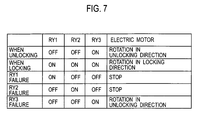
- FIG. 7 illustrates one embodiment of the present invention and illustrates the respective operations of an operation relay and a switching relay.
- FIG. 3 to FIG. 7 illustrate one embodiment of the present invention.
- An electric steering lock device 1 of this embodiment has an electric motor control circuit to operate an electric motor 2 .
- This electric motor control circuit includes a first switching relay RY 1 and a second switching relay RY 2 for switching the rotating direction of the electric motor 2 , an operation relay RY 3 , and a control unit (CPU) 3 .
- the switching relay RY 1 is connected to the first port (PORT 1 ) 3 a of the control unit (CPU) 3 .
- the switching relay RY 2 is connected to the second port (PORT 2 ) 3 b of the control unit (CPU) 3 .
- the operation relay RY 3 is connected to the third port (PORT 3 ) 3 c of the control unit (CPU) 3 .
- the respective relays RY 1 , RY 2 , and RY 3 and the control unit (CPU) 3 have therebetween diodes 4 , 5 , and 6 for energizing the respective relays RY 1 , RY 2 , and RY 3 .
- the electric steering lock device 1 also includes a locking rod (not shown) provided in a steering column of a vehicle. This locking rod is displaced by driving of the electric motor 2 between the lock position at which the steering shaft is locked to prevent the rotation and the unlock position at which the steering shaft is unlocked to allow the rotation.
- the first switching relay RY 1 has a contact point a 1 that is switched to the side of a battery 7 in an OFF status and that is switched to the side of ground 8 when the contact point a 1 is energized by the diode 4 to be in an ON status.
- the second switching relay RY 2 has a contact point a 2 that is switched to the side of the ground 8 in an OFF status and that is switched to the side of the battery 7 when the contact point a 2 is energized by the diode 5 to be in an ON status.
- the operation relay RY 3 has a contact point a 3 that is switched to the side of the first switching relay RY 1 in an OFF status and that is switched to the side of the second switching relay RY 2 when the contact point a 3 is energized by the diode 6 to be in an ON status.
- an unlocking circuit is formed that is composed of the battery 7 -side, the first switching relay RY 1 , the electric motor 2 , the operation relay RY 3 , the second switching relay RY 2 , and the ground 8 -side.
- the electric motor 2 is rotated in the unlocking direction at the time t 3 . This allows the locking rod to be moved to the unlock position, which allows the rotation of the steering shaft. Then, the vehicle can be maneuvered.
- the diodes 4 and 5 energize the switching relays RY 1 and RY 2 in accordance with this first operation signal at the time t 12 to provide an ON status. Then, by the time t 13 is reached, the contact point a 1 of the first switching relay RY 1 is switched to the side of the ground 8 and the contact point a 2 of the second switching relay RY 2 is switched to the side of the battery 7 as shown in FIG. 4 . In this manner, the rotating direction of the electric motor 2 is switched.
- the diode 6 energizes the operation relay RY 3 .
- the contact point a 3 of the operation relay RY 3 is switched to the side of the second switching relay RY 2 at the time t 15 .
- a locking circuit is formed that is composed of the battery 7 -side, the second switching relay RY 2 , the operation relay RY 3 , the electric motor 2 , the first switching relay RY 1 , and the ground 8 -side.
- the electric motor 2 is rotated in the locking direction at the time t 16 .
- the locking rod is moved to the lock position to prevent the steering shaft from being rotated. Then, the vehicle cannot be maneuvered.
- the operation relay RY 3 is de-energized at the time t 18 to switch the contact point a 3 to the side of the first switching relay RY 1 .
- This allows the above locking circuit to be cancelled and the electric motor 2 is stopped at the time t 19 .
- the diodes 4 and 5 de-energize the switching relays RY 1 and RY 2 at the time t 21 .
- the contact point a 1 of the first switching relay RY 1 is switched to the side of the battery 7 and the contact point a 2 of the second switching relay RY 2 is switched to the side of the ground 8 . In this manner, the above locking circuit is cancelled by the time t 22 is reached.
- the present invention even when one of the pair of switching relays RY 1 and RY 2 has a failure and is always in an ON status as shown in FIG. 7 , the other of the switching relays RY 1 and RY 2 is in an OFF status.
- the above failure prevents the electric motor 2 from being rotated in a locking direction.
- the rotation of the steering shaft can be prevented from being blocked.
- an individual failure of one of the pair of switching relays RY 1 or RY 2 does not lock the steering shaft. This can suppress a serious failure where the locked status is caused while the vehicle is running, thus improving the vehicle safety.
- a failure detection circuit for detecting a failure of the electric motor control circuit 10 is not required and thus a lower cost can be realized.
- the operation relay RY 3 When the operation relay RY 3 has a failure and is always in an ON status, the electric motor 2 is continuously rotated in the unlocking direction. However, the rotation of the steering shaft is allowed even when the vehicle is running for example. Thus, the vehicle can be maneuvered and thus no serious problem is caused from a viewpoint of vehicle safety.
- the present invention also uses the relays RY 1 , RY 2 , and RY 3 that requires a lower cost than the case where the H-bridge-type IC is used, thus achieving cost reduction.
- both ends of a terminal of the electric motor 2 are in a short circuit status.
- the locking rod cannot be maneuvered.
- the rotation of the steering shaft is blocked and thus the vehicle cannot be maneuvered thus preventing the parked vehicle from being stolen.
- the operation by the relays RY 1 , RY 2 , and RY 3 causes a relatively small voltage drop.
- a higher voltage is applied to the electric motor 2 and a higher force for driving the locking rod is provided.
- no braking control is required to stop the electric motor 2 , thus reducing the response time for unlocking and locking operations.
- a locking circuit of the electric motor 2 is formed after the rotating direction of the electric motor 2 is switched by the control of the control unit 3 .
- the electric motor 2 is securely rotated in the locking direction.
Landscapes
- Engineering & Computer Science (AREA)
- Mechanical Engineering (AREA)
- Chemical & Material Sciences (AREA)
- Combustion & Propulsion (AREA)
- Transportation (AREA)
- Lock And Its Accessories (AREA)
Abstract
Description
Claims (2)
Applications Claiming Priority (2)
| Application Number | Priority Date | Filing Date | Title |
|---|---|---|---|
| JP2007256092A JP4929116B2 (en) | 2007-09-28 | 2007-09-28 | Electric steering lock device |
| JP2007-256092 | 2007-09-28 |
Publications (2)
| Publication Number | Publication Date |
|---|---|
| US20090084146A1 US20090084146A1 (en) | 2009-04-02 |
| US7714460B2 true US7714460B2 (en) | 2010-05-11 |
Family
ID=40289157
Family Applications (1)
| Application Number | Title | Priority Date | Filing Date |
|---|---|---|---|
| US12/232,866 Expired - Fee Related US7714460B2 (en) | 2007-09-28 | 2008-09-25 | Electric steering lock device |
Country Status (5)
| Country | Link |
|---|---|
| US (1) | US7714460B2 (en) |
| EP (1) | EP2042392B1 (en) |
| JP (1) | JP4929116B2 (en) |
| KR (1) | KR101438239B1 (en) |
| CN (1) | CN101397003B (en) |
Cited By (2)
| Publication number | Priority date | Publication date | Assignee | Title |
|---|---|---|---|---|
| US20120234060A1 (en) * | 2011-03-17 | 2012-09-20 | Kabushiki Kaisha Tokai Rika Denki Seisakusho | Electric steering wheel lock device |
| US11329343B2 (en) * | 2019-04-24 | 2022-05-10 | Mazda Motor Corporation | Battery device for vehicle |
Families Citing this family (5)
| Publication number | Priority date | Publication date | Assignee | Title |
|---|---|---|---|---|
| DE102009054748A1 (en) * | 2009-12-16 | 2011-06-22 | Continental Automotive GmbH, 30165 | Electronic control device for a locking device and steering wheel lock |
| JP5636255B2 (en) * | 2010-10-20 | 2014-12-03 | 株式会社ユーシン | Electric steering lock device |
| JP2013022972A (en) * | 2011-07-15 | 2013-02-04 | Yuhshin Co Ltd | Electric steering lock device |
| JP5990455B2 (en) * | 2012-03-14 | 2016-09-14 | 株式会社東海理化電機製作所 | Electric steering lock device |
| CN104973009A (en) * | 2014-04-14 | 2015-10-14 | 江苏浩昱驰汽车电子有限公司 | Method for controlling electronic steering column lock |
Citations (2)
| Publication number | Priority date | Publication date | Assignee | Title |
|---|---|---|---|---|
| US20050132765A1 (en) * | 2003-12-19 | 2005-06-23 | Kabushiki Kaisha Tokai Rika Denki Seisakusho | Current cutoff circuit and electric steering wheel lock |
| JP2006103489A (en) | 2004-10-05 | 2006-04-20 | Nissan Motor Co Ltd | Electric steering lock device and electric steering lock method |
Family Cites Families (7)
| Publication number | Priority date | Publication date | Assignee | Title |
|---|---|---|---|---|
| DE19945867C2 (en) * | 1999-09-24 | 2002-01-17 | Daimler Chrysler Ag | Electric steering lock device |
| DE10006234A1 (en) * | 2000-02-11 | 2001-08-23 | Siemens Ag | Method and device for controlling an electrical actuation unit |
| JP3851802B2 (en) * | 2001-02-09 | 2006-11-29 | 株式会社東海理化電機製作所 | Electronic vehicle anti-theft device |
| JP4658406B2 (en) * | 2001-08-24 | 2011-03-23 | 株式会社東海理化電機製作所 | Electronic vehicle anti-theft device |
| JP2003112602A (en) * | 2001-10-04 | 2003-04-15 | Tokai Rika Co Ltd | Electronic vehicle anti-theft device |
| JP2006062627A (en) * | 2004-08-30 | 2006-03-09 | Nissan Motor Co Ltd | Steering reaction force control device |
| JP2006273115A (en) * | 2005-03-29 | 2006-10-12 | Alpha Corp | Electric steering lock device and control method of electric steering lock device |
-
2007
- 2007-09-28 JP JP2007256092A patent/JP4929116B2/en not_active Expired - Fee Related
-
2008
- 2008-09-25 US US12/232,866 patent/US7714460B2/en not_active Expired - Fee Related
- 2008-09-26 KR KR1020080094616A patent/KR101438239B1/en not_active Expired - Fee Related
- 2008-09-26 CN CN2008101663887A patent/CN101397003B/en not_active Expired - Fee Related
- 2008-09-26 EP EP08017020.2A patent/EP2042392B1/en not_active Ceased
Patent Citations (2)
| Publication number | Priority date | Publication date | Assignee | Title |
|---|---|---|---|---|
| US20050132765A1 (en) * | 2003-12-19 | 2005-06-23 | Kabushiki Kaisha Tokai Rika Denki Seisakusho | Current cutoff circuit and electric steering wheel lock |
| JP2006103489A (en) | 2004-10-05 | 2006-04-20 | Nissan Motor Co Ltd | Electric steering lock device and electric steering lock method |
Cited By (3)
| Publication number | Priority date | Publication date | Assignee | Title |
|---|---|---|---|---|
| US20120234060A1 (en) * | 2011-03-17 | 2012-09-20 | Kabushiki Kaisha Tokai Rika Denki Seisakusho | Electric steering wheel lock device |
| US9035488B2 (en) * | 2011-03-17 | 2015-05-19 | Kabushiki Kaisha Tokai Rika Denki Seisakusho | Electric steering wheel lock device |
| US11329343B2 (en) * | 2019-04-24 | 2022-05-10 | Mazda Motor Corporation | Battery device for vehicle |
Also Published As
| Publication number | Publication date |
|---|---|
| CN101397003B (en) | 2012-07-25 |
| JP4929116B2 (en) | 2012-05-09 |
| KR101438239B1 (en) | 2014-09-05 |
| JP2009083661A (en) | 2009-04-23 |
| EP2042392A2 (en) | 2009-04-01 |
| US20090084146A1 (en) | 2009-04-02 |
| CN101397003A (en) | 2009-04-01 |
| EP2042392B1 (en) | 2017-05-17 |
| KR20090033098A (en) | 2009-04-01 |
| EP2042392A3 (en) | 2012-12-26 |
Similar Documents
| Publication | Publication Date | Title |
|---|---|---|
| US7714460B2 (en) | Electric steering lock device | |
| US8122994B2 (en) | Method and device for operating a vehicle with a steering system, and a steering system | |
| US8528689B2 (en) | Motor drive apparatus and method, and electric power steering system using the same | |
| US7628245B2 (en) | Vehicle steering apparatus | |
| US8818597B2 (en) | Vehicle control device | |
| KR20110124786A (en) | Door control system for railroad cars | |
| EP2790318B1 (en) | Electronic control device having power supply voltage monitoring function and vehicle steering control device equipped with same | |
| JP2005244334A (en) | Semiconductor switch | |
| US20030060327A1 (en) | System with controller and method for controlling a park-interlock device in a vehicle | |
| US9302656B2 (en) | Electromechanical parking brake device and electronic system for operating same | |
| US20090260408A1 (en) | Motor-driven steering lock apparatus | |
| US8055410B2 (en) | Electric power steering system | |
| CN120641676A (en) | Method, computer program, computer program product and vehicle for learning at least one locking position of a locking actuator | |
| JPH11148415A (en) | Method and control system for stopping a car | |
| KR101040390B1 (en) | Steering Shaft Lock, Unlock System | |
| US9828000B2 (en) | Method and device for controlling a vehicle | |
| EP4109739A1 (en) | Shift device and vehicular motor control device | |
| KR100504276B1 (en) | neutral position returning method of steering wheel | |
| JP2004338657A (en) | Vehicle steering system | |
| KR20140118145A (en) | Steering device and its control method for vehicle | |
| JP6824391B2 (en) | Electronic control device and control method to realize safe park lock | |
| KR20150062362A (en) | Electronic key system for vehicle | |
| KR100825490B1 (en) | Steering Column Lock Motor Control System of Vehicle | |
| JP5496059B2 (en) | Electric steering lock control device | |
| JP2010137632A (en) | Anti-theft device for vehicle |
Legal Events
| Date | Code | Title | Description |
|---|---|---|---|
| AS | Assignment |
Owner name: ALPHA CORPORATION, JAPAN Free format text: ASSIGNMENT OF ASSIGNORS INTEREST;ASSIGNOR:YABUMOTO, KAZUHISA;REEL/FRAME:021674/0660 Effective date: 20080916 Owner name: ALPHA CORPORATION,JAPAN Free format text: ASSIGNMENT OF ASSIGNORS INTEREST;ASSIGNOR:YABUMOTO, KAZUHISA;REEL/FRAME:021674/0660 Effective date: 20080916 |
|
| STCF | Information on status: patent grant |
Free format text: PATENTED CASE |
|
| FEPP | Fee payment procedure |
Free format text: PAYOR NUMBER ASSIGNED (ORIGINAL EVENT CODE: ASPN); ENTITY STATUS OF PATENT OWNER: LARGE ENTITY |
|
| FPAY | Fee payment |
Year of fee payment: 4 |
|
| MAFP | Maintenance fee payment |
Free format text: PAYMENT OF MAINTENANCE FEE, 8TH YEAR, LARGE ENTITY (ORIGINAL EVENT CODE: M1552) Year of fee payment: 8 |
|
| LAPS | Lapse for failure to pay maintenance fees |
Free format text: PATENT EXPIRED FOR FAILURE TO PAY MAINTENANCE FEES (ORIGINAL EVENT CODE: EXP.); ENTITY STATUS OF PATENT OWNER: LARGE ENTITY |
|
| FEPP | Fee payment procedure |
Free format text: MAINTENANCE FEE REMINDER MAILED (ORIGINAL EVENT CODE: REM.); ENTITY STATUS OF PATENT OWNER: LARGE ENTITY |
|
| STCH | Information on status: patent discontinuation |
Free format text: PATENT EXPIRED DUE TO NONPAYMENT OF MAINTENANCE FEES UNDER 37 CFR 1.362 |
|
| FP | Lapsed due to failure to pay maintenance fee |
Effective date: 20220511 |