US7703827B2 - Motor vehicle hatch with a storable rear window - Google Patents
Motor vehicle hatch with a storable rear window Download PDFInfo
- Publication number
- US7703827B2 US7703827B2 US10/574,245 US57424504A US7703827B2 US 7703827 B2 US7703827 B2 US 7703827B2 US 57424504 A US57424504 A US 57424504A US 7703827 B2 US7703827 B2 US 7703827B2
- Authority
- US
- United States
- Prior art keywords
- rear window
- hatch
- motor vehicle
- accordance
- automobile body
- Prior art date
- Legal status (The legal status is an assumption and is not a legal conclusion. Google has not performed a legal analysis and makes no representation as to the accuracy of the status listed.)
- Expired - Fee Related
Links
Images




Classifications
-
- B—PERFORMING OPERATIONS; TRANSPORTING
- B60—VEHICLES IN GENERAL
- B60J—WINDOWS, WINDSCREENS, NON-FIXED ROOFS, DOORS, OR SIMILAR DEVICES FOR VEHICLES; REMOVABLE EXTERNAL PROTECTIVE COVERINGS SPECIALLY ADAPTED FOR VEHICLES
- B60J1/00—Windows; Windscreens; Accessories therefor
- B60J1/18—Windows; Windscreens; Accessories therefor arranged at the vehicle rear
- B60J1/1807—Windows; Windscreens; Accessories therefor arranged at the vehicle rear movable for vehicles with convertible top
- B60J1/1823—Windows; Windscreens; Accessories therefor arranged at the vehicle rear movable for vehicles with convertible top adjustable relative to hard- or soft-top, e.g. pivotable
-
- B—PERFORMING OPERATIONS; TRANSPORTING
- B60—VEHICLES IN GENERAL
- B60J—WINDOWS, WINDSCREENS, NON-FIXED ROOFS, DOORS, OR SIMILAR DEVICES FOR VEHICLES; REMOVABLE EXTERNAL PROTECTIVE COVERINGS SPECIALLY ADAPTED FOR VEHICLES
- B60J7/00—Non-fixed roofs; Roofs with movable panels, e.g. rotary sunroofs
- B60J7/02—Non-fixed roofs; Roofs with movable panels, e.g. rotary sunroofs of sliding type, e.g. comprising guide shoes
- B60J7/04—Non-fixed roofs; Roofs with movable panels, e.g. rotary sunroofs of sliding type, e.g. comprising guide shoes with rigid plate-like element or elements, e.g. open roofs with harmonica-type folding rigid panels
Definitions
- the invention concerns a motor vehicle with a hatch that includes a rear window, wherein the rear window can be moved separately into a released position.
- DE 296 22 436 U1 discloses a motor vehicle that has a hatch with a rear window, which, to improve the open-air feeling for the occupants of the vehicle, can be moved downward into a lower region of the hatch and thus opens the space that it occupies in its closed position.
- This type of displacement of the rear window is possible only if the lower region of the hatch has a sufficiently bend-free height for receiving the window, which is usually possible only for vehicles with vertical hatches or vehicles with oblique hatches that extend a very long distance downward.
- the objective of the invention is to expand the design possibilities for designers in vehicles of the aforementioned type.
- the invention achieves independence of the design of the region of the hatch situated below the rear window from the requirement that a space for housing the opened rear window be made available. Therefore, the lower region can be designed, for example, as a relatively narrow sector or as a region with multiple bends and can have a vertical extent that is considerably smaller than the vertical extent of the rear window.
- the rear window can be lowered with the hatch in the open position, cost-effective manual operation can be simplified, for example, by virtue of the fact that the open hatch is acted on from the side that is on the inside when the hatch is closed.
- lowering kinematics for conveying the rear window into its released position are possible, which only slightly touches the luggage compartment situated below, even during the lowering movement.
- the hatch when the window is in the released position, the hatch can form a large, opening that extends continuously towards the front without interruption by a transverse support.
- the open-air feeling is especially pronounced in this case.
- the open-air feeling is improved if, in the closed position of the rear window, its upper and front edge (with respect to the direction of travel of the vehicle) is followed by at least one additional panel section that can be moved for opening.
- FIG. 1 shows an oblique rear perspective view of a motor vehicle of the invention with a closed rear window and a hatch in the closed position and with two other movable panel sections in front of the upper and front edge of the hatch (with respect to the direction of travel of the vehicle).
- FIG. 2 shows a view similar to that of FIG. 1 after the forwardmost panel section has been opened.
- FIG. 3 shows a view similar to that of FIG. 2 with the hatch in the open position.
- FIG. 4 shows a view similar to that of FIG. 3 during the opening of the two front panel sections.
- FIG. 5 shows a view similar to that of FIG. 4 with further progression of the opening of the front panel sections.
- FIG. 6 shows a view similar to that of FIG. 5 with the front panel sections lowered essentially vertically into the automobile body.
- FIG. 7 shows a view similar to that of FIG. 6 with the rear window also lowered in its released position in the automobile body.
- FIG. 8 shows a view similar to that of FIG. 7 after the hatch has been closed.
- FIG. 9 shows a schematic side view of the vehicle in the roof position according to FIG. 1 .
- FIG. 10 shows a view similar to that of FIG. 9 but after the forwardmost panel section has been opened corresponding to the roof position of FIG. 2 .
- FIG. 11 shows a view similar to that of FIG. 10 but with the hatch in the open position corresponding to the roof position of FIG. 3 .
- FIG. 12 shows a view similar to that of FIG. 11 but during the opening of the two front panel sections corresponding to the roof position of FIG. 4 .
- FIG. 13 shows a view similar to that of FIG. 12 but during further progression of the opening of the front panel sections corresponding to the roof position of FIG. 5 .
- FIG. 14 shows a view similar to that of FIG. 9 but with completely opened front panel sections corresponding to the roof position of FIG. 6 .
- FIG. 15 shows a view similar to that of FIG. 14 but as the rear window is being swung out of its closed position in the hatch.
- FIG. 16 shows a view similar to that of FIG. 15 with further progression of the opening of the rear window.
- FIG. 17 shows a view similar to that of FIG. 16 with the rear window completely in its released position corresponding to the position of FIG. 7 .
- FIG. 18 shows a view similar to that of FIG. 17 after the hatch has been moved into its closed position corresponding to the position of FIG. 8 .
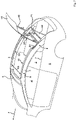
- FIG. 19 shows an alternative design of the kinematic system for conveying the rear window into the released position, wherein the kinematic system contains separate lateral guide rails, with the front panel sections lowered and the hatch closed with the rear window in the closed position.
- FIG. 20 shows a view similar to that of FIG. 19 with the hatch opened.
- FIG. 21 shows a view similar to that of FIG. 20 during the movement of the rear window out of the parts of the hatch that surround it into the released position.
- FIG. 22 shows a view similar to that of FIG. 21 with the rear window in its released position.
- FIG. 23 shows a view similar to that of FIG. 22 after the hatch has been closed.
- the drawings generally show a four-seat or five-seat motor vehicle 1 with a rear seat. However, this is not required.
- a two-seat motor vehicle can also be designed in accordance with the invention.
- the vehicle 1 has side windows 2 that are bounded above by intrinsically rigid roof rails 3 , which, as viewed from above, run essentially lengthwise in the longitudinal direction of the vehicle between a windshield frame 4 and the rear section 5 of the vehicle, and which have a curved shape as viewed from the side.
- These roof rails are part of the automobile body 6 .
- the rear section 5 has a hatch H 1 .
- the hatch H 1 has an essentially U-shaped design here with a lower crosspiece H 2 , which can contain, for example, parts of the taillights and/or a license plate mount, and with side pieces H 3 , which, in the closed position of the hatch H 1 , are directed forward and upward in the direction of vehicle travel F and follow the curve of the roof rails 3 .
- An especially rigid rear window H 4 which can consist, for example, of plastic or, advantageously, glass, is held between the parts H 2 and H 3 in its closed position. In this position, the side pieces H 3 thus serve as lateral frame parts of the rear window H 4 .
- the upper and forward edge H 5 of the rear window H 4 in the direction of vehicle travel F simultaneously forms the upper and forward edge of the hatch H 1 and is not supported from below by a transverse support due to the U-shape of the hatch H 1 .
- the hatch H 1 is movably supported all together between a closed position ( FIG. 1 ) and an open position ( FIG. 3 ).
- the opening movement is not a pure swinging movement but rather occurs in such a way that in its open position, the front edge H 5 of the hatch H 1 is moved towards the rear relative to its closed position.
- the hatch H 1 is supported ( FIGS. 9 ff.) on each side of the vehicle, for example, by a multijoint linkage, which in the present case is a four-bar linkage H 6 .
- the links H 7 and H 8 of the linkage H 6 are each articulated laterally in the automobile body 6 , for example, in the rear region of the roof rails 3 .
- the rear window H 4 can be lowered from the open position of the hatch H 1 shown in FIGS. 3 and 12 into its separate released position in the automobile body 6 .
- the rear window H 4 is connected with the automobile body 6 by linkage parts H 9 , H 10 arranged laterally in the body 6 .
- Linkage part H 9 is a cylinder that can be extended and retracted. Due to its length variability, even when the rear window H 4 is closed, the linkage part H 9 is able to move along with the opening movement of the hatch H 1 , which then encloses the rear window (transition from FIG. 1 to FIG. 3 ).
- the cylinder H 9 is articulated at one end to the automobile body 6 . Its-free end acts on another link H 10 , which is articulated higher in the automobile body 6 , and this point of application of force to the link H 10 by the link H 9 is located some distance from the articulation H 11 of the link H 10 , so that a lever arm is produced.
- the free end of the link H 10 acts laterally to the upper edge H 5 of the rear window H 4 .
- the rear window H 4 is first unlocked at its end H 12 , which forms the lower edge in the closed position, from the lower crosspiece H 2 of the hatch H 1 (transition from FIG. 14 to FIG. 15 ), and the rear window H 4 can be manually held by a user at its lateral edges H 13 and manually moved almost parallel downward ( FIG. 16 ).
- the lever H 10 is swung downward about the joint H 11 , and the cylinder H 9 retracts and swings forward. All together, the rear window H 4 is thus lowered at least almost vertically and displaced slightly forward to save space. In its lowered position, it is stowed with other roof parts as a group, which will be explained in greater detail below.
- the rear window H 4 can be moved into its released position by lateral guide rail sections H 14 , H 15 .
- the guide rail H 14 , H 15 is divided into two sections to allow its continuation over the roof rails 3 when the hatch H 1 is open ( FIG. 20 ) but also to allow the hatch H 1 to ride over the guide rail when the hatch H 1 is closed ( FIG. 19 ).
- the first section H 14 of the guide rail is coordinated with the four-bar linkage H 6 and is moved into an upright position by a first link H 7 when the hatch H 1 is opened, which causes it to become automatically aligned with the lower section H 15 of the guide rail, which is fixed in the automobile body 6 (transition from FIG. 19 to FIG. 20 ).
- the rear window H 4 is first unlocked at its end H 12 , which forms the lower edge in the closed position, from the lower crosspiece H 2 of the hatch H 1 (transition from FIG. 20 to FIG. 21 ), and the rear window H 4 is manually held by a user at its lateral edges H 13 and can be manually moved almost parallel downward in the guide rail H 14 , H 15 by means of bearing journals H 16 located in the lateral region of the upper edge H 5 ( FIG. 21 ).
- the rear window H 4 is lowered at least almost vertically into its released position, in which it is displaced slightly forward to save space, and is held below a lateral belt line 7 of the automobile body 6 .
- the hatch H 1 can then be closed again ( FIG. 23 ).
- the motor vehicle 1 in the closed position of the rear window H 4 ( FIG. 1 ), has additional movable panel sections P 1 , P 2 immediately in front of the front edge H 5 of the rear window H 4 with respect to the direction of vehicle travel.
- the number of these panels is variable, depending on the length of the roof. In the closed state, they are arranged essentially horizontally one behind the other, are flush with each other and are flush with the rear window H 4 . They are supported directly or indirectly on the lateral roof rails 3 .
- the (in this case) two roof sections P 1 and P 2 can be made of various materials, such as metallic, glass or plastic materials. In particular, they can be essentially transparent materials.
- the roof sections P 1 , P 2 not be made too narrow in the longitudinal-direction of the vehicle. Therefore, a minimum length of 40 cm in the longitudinal direction of the vehicle is advantageous.
- the front roof section P 1 can be moved in the manner of a sliding sunroof from the closed position to a position over the rear roof section P 2 . In its opened position, it rests essentially parallel on roof section P 2 ( FIGS. 2 ff.).
- the position of the roof sections P 1 , P 2 produced in this way represents a possible permanent driving position. However, from this position, the roof can be opened further with a downward displacement of the combined stack P 3 of roof sections P 1 and P 2 , which is lowered within the automobile body 6 .
- the stacked group of roof sections P 3 formed in this way is supported in the rear region of the rear roof section P 2 by two guide rollers P 4 , P 5 arranged one behind the other in a lateral guide rail P 6 .
- the front guide roller P 4 runs in a section of the guideway P 6 that follows the curve of the lateral roof rails 3 , so that with the almost vertical downward movement of the rear guide roller P 5 , the steep orientation of the stack of roof sections P 3 increases, and when the front guide roller P 4 also enters the section P 10 , the stack P 3 assumes an almost vertical position ( FIG. 13 ). In this position, it can slide downward to the inner vehicle base P 12 and assume an almost vertical position slightly behind the backrests P 13 of the second row of seats to save space ( FIG. 14 ).
- the closing of the roof sections P 1 , P 2 proceeds correspondingly but in the opposite direction, and in this operation as well, the head clearance does not during any phase of the movement fall below the amount of head clearance present when the roof sections are closed.
- the vehicle silhouette can thus be kept very flat and sporty.
- the lateral autobody sections 3 above the side windows can also be designed very narrow, so that the width of the panel sections P 1 and P 2 can extend almost to the upper edge of the side windows.
- the hatch H 1 can open in such a way that in its open position, the front edge H 5 is displaced to the rear relative to its closed position. This results in a passage space D 1 in front of the opened hatch H 1 with respect to the direction of vehicle travel F, and this passage space D 1 lies completely behind the rear edge of the rear roof section P 2 in its closed state. In this way, the lowering path of the stack of roof sections P 3 through the interior of the vehicle can be shifted far to the rear in the vehicle 1 . Any passengers that may be seated in the back seat are not disturbed by the lowering operation.
- the frame parts H 3 which laterally frame the rear window H 4 , can be aligned with the roof rails 3 , which follow them towards the front in the direction of travel.
- a very advantageous visual effect is achieved in this way.
- no gradation is necessary in the inner edge D 2 of the specified sections H 3 , 3 that faces the rear window H 4 and the moving roof sections P 1 , P 2 , but rather this edge D 2 runs straight over the entire interior.
- a guide rail P 14 which projects laterally beyond the roof section P 2 and in which the front roof part P 1 is guided in its open position, can additionally enter the interior of the automobile body 6 with the stack of roof sections P 3 through the widened passage space D 1 .
- the hatch H 1 is first opened to free the passage space D 1 .
- the roof sections P 1 , P 2 can then be opened in the manner described above.
- the rear window H 4 can be opened out of the frame pieces H 2 , H 3 in one of the aforementioned ways and lowered into the interior in a space-saving position parallel to the roof sections P 1 and P 2 . It is also possible to open only the rear window H 4 ; only the front panel section P 1 ; the rear window H 4 and the panel section P 1 ; or only the two forward roof sections P 1 and P 2 .
- the invention can be used both in vehicles with manually moved roof sections P 1 , P 2 , H 4 and in vehicles with fully automatically or semiautomatically moved roof sections.
Landscapes
- Engineering & Computer Science (AREA)
- Mechanical Engineering (AREA)
- Window Of Vehicle (AREA)
- Body Structure For Vehicles (AREA)
Applications Claiming Priority (4)
| Application Number | Priority Date | Filing Date | Title |
|---|---|---|---|
| DE10345274.5 | 2003-09-30 | ||
| DE10345274 | 2003-09-30 | ||
| DE10345274A DE10345274A1 (de) | 2003-09-30 | 2003-09-30 | Kraftfahrzeug |
| PCT/DE2004/002084 WO2005039906A1 (de) | 2003-09-30 | 2004-09-17 | Kfz-heckklappe mit ablegbarer heckscheibe |
Publications (2)
| Publication Number | Publication Date |
|---|---|
| US20070262610A1 US20070262610A1 (en) | 2007-11-15 |
| US7703827B2 true US7703827B2 (en) | 2010-04-27 |
Family
ID=34353197
Family Applications (1)
| Application Number | Title | Priority Date | Filing Date |
|---|---|---|---|
| US10/574,245 Expired - Fee Related US7703827B2 (en) | 2003-09-30 | 2004-09-17 | Motor vehicle hatch with a storable rear window |
Country Status (4)
| Country | Link |
|---|---|
| US (1) | US7703827B2 (de) |
| EP (1) | EP1670654B1 (de) |
| DE (2) | DE10345274A1 (de) |
| WO (1) | WO2005039906A1 (de) |
Cited By (3)
| Publication number | Priority date | Publication date | Assignee | Title |
|---|---|---|---|---|
| US20100230998A1 (en) * | 2009-03-12 | 2010-09-16 | Magna Car Top Systems Gmbh | Convertible Top with Skylight |
| US20170275931A1 (en) * | 2016-03-22 | 2017-09-28 | Ford Global Technologies, Llc | Lock system for dual vehicle closures |
| US20230052773A1 (en) * | 2020-01-31 | 2023-02-16 | Automobili Lamborghini S.P.A. | Method for opening and closing a vehicle roof, corresponding opening and closing system and vehicle |
Families Citing this family (10)
| Publication number | Priority date | Publication date | Assignee | Title |
|---|---|---|---|---|
| DE102006008086A1 (de) * | 2006-02-22 | 2007-08-23 | Daimlerchrysler Ag | Heckscheibenanordnung für einen Kraftwagen |
| DE102006018173B3 (de) * | 2006-04-18 | 2007-12-20 | Magna Car Top Systems Gmbh | Zwischen einer Schließ- und einer Ablageposition verstellbares Fahrzeugdach |
| FR2913373B1 (fr) * | 2007-03-07 | 2011-04-15 | Peugeot Citroen Automobiles Sa | Vehicule automobile decouvrable. |
| US20080302014A1 (en) * | 2007-06-05 | 2008-12-11 | Gm Global Technology Operations, Inc. | Method and apparatus for positioning a motor actuated vehicle accessory |
| US20090045655A1 (en) * | 2007-08-16 | 2009-02-19 | Magna Car Top Systems Gmbh | Multi-Panel Panoramic Roof Module |
| DE102007060364B4 (de) | 2007-12-12 | 2022-12-15 | Valmet Automotive Oy | Kraftfahrzeug mit einer separat beweglichen, eine Heckscheibe umfassenden Baueinheit |
| DE102011122675B3 (de) * | 2011-12-30 | 2012-12-27 | Valmet Automotive Oy | Kraftfahrzeug mit verlagerbarem Dach |
| US9186960B2 (en) * | 2013-02-13 | 2015-11-17 | Webasto-Edscha Cabrio GmbH | Assemblies to articulate a vehicle backlite |
| DE102014010962A1 (de) * | 2014-07-25 | 2016-01-28 | Audi Ag | Verdeck für ein öffnungsfähiges Fahrzeugdach |
| DE102018117521B4 (de) * | 2017-12-11 | 2024-02-08 | Webasto SE | Fahrzeugaufbau mit starrem Verdeckelement und öffenbarer Heckscheibe |
Citations (19)
| Publication number | Priority date | Publication date | Assignee | Title |
|---|---|---|---|---|
| US4895409A (en) * | 1987-01-12 | 1990-01-23 | Mazda Motor Corporation | Convertible vehicle body structure |
| DE3843674A1 (de) | 1988-12-23 | 1990-06-28 | Bayerische Motoren Werke Ag | Heckfenster fuer mit heckklappe ausgestattete kraftfahrzeuge, insbesondere personenkraftwagen |
| DE29622436U1 (de) | 1996-12-28 | 1998-01-08 | Wilhelm Karmann GmbH, 49084 Osnabrück | Kraftfahrzeug |
| US5769483A (en) * | 1994-09-30 | 1998-06-23 | Webasto Karosseriesysteme Gmbh | Convertible motor vehicle roof |
| DE29804387U1 (de) | 1998-03-12 | 1999-07-15 | Strobel, Martin, Dipl.-Designer, 64823 Groß-Umstadt | Schiebedach |
| US6131988A (en) * | 1998-05-12 | 2000-10-17 | France Design | Three-part folding roof for convertible vehicles |
| WO2001014158A1 (fr) | 1999-08-24 | 2001-03-01 | Peugeot Citroen Automobiles | Module de recouvrement d'un habitacle automobile et vehicule automobile equipe d'un tel habitacle |
| FR2806969A1 (fr) | 2000-04-04 | 2001-10-05 | Webasto Systemes Carrosserie | Vehicule automobile a lunette escamotable |
| US20020135200A1 (en) * | 2000-05-23 | 2002-09-26 | Francosis De Gaillard | Vehicle with a vehicle roof that can be opened |
| US20020158485A1 (en) * | 2001-04-04 | 2002-10-31 | Edscha Cabrio-Dachsysteme Gmbh | Retractable top with rear-window control |
| US6511118B2 (en) * | 2000-08-14 | 2003-01-28 | Wilhelm Karmann Gmbh | Convertible vehicle |
| US6582009B2 (en) * | 2001-03-19 | 2003-06-24 | Cts Fahrzeug-Dachsysteme Gmbh | Convertible vehicle with a wind deflector |
| US6783170B1 (en) * | 2003-01-04 | 2004-08-31 | Ford Global Technologies, Llc | Backlite storage and convertible decklid system for automotive vehicle |
| US6843523B2 (en) * | 2002-09-19 | 2005-01-18 | Edscha Roof Systems Inc. | Stowage cover for a convertible top |
| US20050104411A1 (en) * | 2003-11-17 | 2005-05-19 | Kanto Auto Works, Ltd. | Convertible vehicle |
| US20060255619A1 (en) * | 2005-05-16 | 2006-11-16 | Dickie Robert B | Retractable hard top for a four door vehicle |
| US20070187984A1 (en) * | 2004-05-03 | 2007-08-16 | Wilhelm Karmann Gmbh | Convertible vehicle |
| US20070187985A1 (en) * | 2006-02-10 | 2007-08-16 | Aisin Seiki Kabushiki Kaisha | Vehicle roof automatic opening/closing device |
| US20070210610A1 (en) * | 2003-09-30 | 2007-09-13 | Winfried Bunsmann | Motor Vehicle Comprising A Fully Opening Roof Part |
-
2003
- 2003-09-30 DE DE10345274A patent/DE10345274A1/de not_active Ceased
-
2004
- 2004-09-17 US US10/574,245 patent/US7703827B2/en not_active Expired - Fee Related
- 2004-09-17 WO PCT/DE2004/002084 patent/WO2005039906A1/de not_active Ceased
- 2004-09-17 DE DE502004008548T patent/DE502004008548D1/de not_active Expired - Lifetime
- 2004-09-17 EP EP04786803A patent/EP1670654B1/de not_active Expired - Lifetime
Patent Citations (19)
| Publication number | Priority date | Publication date | Assignee | Title |
|---|---|---|---|---|
| US4895409A (en) * | 1987-01-12 | 1990-01-23 | Mazda Motor Corporation | Convertible vehicle body structure |
| DE3843674A1 (de) | 1988-12-23 | 1990-06-28 | Bayerische Motoren Werke Ag | Heckfenster fuer mit heckklappe ausgestattete kraftfahrzeuge, insbesondere personenkraftwagen |
| US5769483A (en) * | 1994-09-30 | 1998-06-23 | Webasto Karosseriesysteme Gmbh | Convertible motor vehicle roof |
| DE29622436U1 (de) | 1996-12-28 | 1998-01-08 | Wilhelm Karmann GmbH, 49084 Osnabrück | Kraftfahrzeug |
| DE29804387U1 (de) | 1998-03-12 | 1999-07-15 | Strobel, Martin, Dipl.-Designer, 64823 Groß-Umstadt | Schiebedach |
| US6131988A (en) * | 1998-05-12 | 2000-10-17 | France Design | Three-part folding roof for convertible vehicles |
| WO2001014158A1 (fr) | 1999-08-24 | 2001-03-01 | Peugeot Citroen Automobiles | Module de recouvrement d'un habitacle automobile et vehicule automobile equipe d'un tel habitacle |
| FR2806969A1 (fr) | 2000-04-04 | 2001-10-05 | Webasto Systemes Carrosserie | Vehicule automobile a lunette escamotable |
| US20020135200A1 (en) * | 2000-05-23 | 2002-09-26 | Francosis De Gaillard | Vehicle with a vehicle roof that can be opened |
| US6511118B2 (en) * | 2000-08-14 | 2003-01-28 | Wilhelm Karmann Gmbh | Convertible vehicle |
| US6582009B2 (en) * | 2001-03-19 | 2003-06-24 | Cts Fahrzeug-Dachsysteme Gmbh | Convertible vehicle with a wind deflector |
| US20020158485A1 (en) * | 2001-04-04 | 2002-10-31 | Edscha Cabrio-Dachsysteme Gmbh | Retractable top with rear-window control |
| US6843523B2 (en) * | 2002-09-19 | 2005-01-18 | Edscha Roof Systems Inc. | Stowage cover for a convertible top |
| US6783170B1 (en) * | 2003-01-04 | 2004-08-31 | Ford Global Technologies, Llc | Backlite storage and convertible decklid system for automotive vehicle |
| US20070210610A1 (en) * | 2003-09-30 | 2007-09-13 | Winfried Bunsmann | Motor Vehicle Comprising A Fully Opening Roof Part |
| US20050104411A1 (en) * | 2003-11-17 | 2005-05-19 | Kanto Auto Works, Ltd. | Convertible vehicle |
| US20070187984A1 (en) * | 2004-05-03 | 2007-08-16 | Wilhelm Karmann Gmbh | Convertible vehicle |
| US20060255619A1 (en) * | 2005-05-16 | 2006-11-16 | Dickie Robert B | Retractable hard top for a four door vehicle |
| US20070187985A1 (en) * | 2006-02-10 | 2007-08-16 | Aisin Seiki Kabushiki Kaisha | Vehicle roof automatic opening/closing device |
Cited By (6)
| Publication number | Priority date | Publication date | Assignee | Title |
|---|---|---|---|---|
| US20100230998A1 (en) * | 2009-03-12 | 2010-09-16 | Magna Car Top Systems Gmbh | Convertible Top with Skylight |
| US7896422B2 (en) * | 2009-03-12 | 2011-03-01 | Magna Car Top Systems Gmbh | Convertible top with skylight |
| US20170275931A1 (en) * | 2016-03-22 | 2017-09-28 | Ford Global Technologies, Llc | Lock system for dual vehicle closures |
| US9945161B2 (en) * | 2016-03-22 | 2018-04-17 | Ford Global Technologies, Llc | Lock system for dual vehicle closures |
| US20230052773A1 (en) * | 2020-01-31 | 2023-02-16 | Automobili Lamborghini S.P.A. | Method for opening and closing a vehicle roof, corresponding opening and closing system and vehicle |
| US12030372B2 (en) * | 2020-01-31 | 2024-07-09 | Automobili Lamborghini S.P.A. | Method for opening and closing a vehicle roof, corresponding opening and closing system and vehicle |
Also Published As
| Publication number | Publication date |
|---|---|
| EP1670654B1 (de) | 2008-11-26 |
| WO2005039906A1 (de) | 2005-05-06 |
| DE10345274A1 (de) | 2005-04-21 |
| DE502004008548D1 (de) | 2009-01-08 |
| EP1670654A1 (de) | 2006-06-21 |
| US20070262610A1 (en) | 2007-11-15 |
Similar Documents
| Publication | Publication Date | Title |
|---|---|---|
| US7591500B2 (en) | Motor vehicle comprising a fully opening roof part | |
| US6431636B1 (en) | Convertible vehicle roof and convertible vehicle | |
| US4801174A (en) | Transparent roof convertible automobile | |
| US6474731B2 (en) | Motor vehicle with an openable vehicle roof | |
| US5975620A (en) | Passenger car having a lowerable vehicle roof | |
| US7156446B2 (en) | Hard-top convertible roof | |
| US7703827B2 (en) | Motor vehicle hatch with a storable rear window | |
| US20020135200A1 (en) | Vehicle with a vehicle roof that can be opened | |
| US20080164726A1 (en) | Multi-panel sunroof system | |
| JPH11235928A (ja) | 格納可能なルーフ構造体を備えた自動車 | |
| US7922232B2 (en) | Movable multisection roof for a motor vehicle | |
| US20050073167A1 (en) | Motor vehicle with improved rear functionality | |
| US6767044B2 (en) | Roof construction for an automotive vehicle | |
| US6938943B2 (en) | Top for a convertible vehicle | |
| US6296295B1 (en) | Motor vehicle with a convertible top | |
| US6644715B1 (en) | Convertible vehicle with through-openings for linkage elements | |
| US20080315632A1 (en) | Vehicle with an Opening Roof | |
| US7784850B2 (en) | Cabriolet | |
| US8056956B2 (en) | Convertible roof with sun roof part | |
| US7172242B2 (en) | Motor vehicle | |
| US7686377B2 (en) | Convertible with a roof which can be stored below a covering | |
| US20080030044A1 (en) | Roof Structure for a Rigid, Openable Vehicle Roof | |
| US7506915B2 (en) | Motor vehicle with a hatchback and opening roof part | |
| US7416246B2 (en) | Motor vehicle with at least two movable parts | |
| US20090146461A1 (en) | Motor vehicle equipped with a roof that can be opened |
Legal Events
| Date | Code | Title | Description |
|---|---|---|---|
| AS | Assignment |
Owner name: WILHELM KARMANN GMBH, GERMANY Free format text: ASSIGNMENT OF ASSIGNORS INTEREST;ASSIGNORS:BUNSMANN, WINFRIED;WEISSMULLER, OLAF;HESELHAUS, UDO;REEL/FRAME:019308/0423 Effective date: 20060717 Owner name: WILHELM KARMANN GMBH,GERMANY Free format text: ASSIGNMENT OF ASSIGNORS INTEREST;ASSIGNORS:BUNSMANN, WINFRIED;WEISSMULLER, OLAF;HESELHAUS, UDO;REEL/FRAME:019308/0423 Effective date: 20060717 |
|
| FPAY | Fee payment |
Year of fee payment: 4 |
|
| AS | Assignment |
Owner name: VALMET AUTOMOTIVE OY, FINLAND Free format text: ASSIGNMENT OF ASSIGNORS INTEREST;ASSIGNOR:WILHELM KARMANN GMBH;REEL/FRAME:031485/0597 Effective date: 20130610 |
|
| FEPP | Fee payment procedure |
Free format text: MAINTENANCE FEE REMINDER MAILED (ORIGINAL EVENT CODE: REM.) |
|
| LAPS | Lapse for failure to pay maintenance fees |
Free format text: PATENT EXPIRED FOR FAILURE TO PAY MAINTENANCE FEES (ORIGINAL EVENT CODE: EXP.) |
|
| STCH | Information on status: patent discontinuation |
Free format text: PATENT EXPIRED DUE TO NONPAYMENT OF MAINTENANCE FEES UNDER 37 CFR 1.362 |
|
| FP | Lapsed due to failure to pay maintenance fee |
Effective date: 20180427 |