US7690728B2 - Vehicle seat apparatus - Google Patents
Vehicle seat apparatus Download PDFInfo
- Publication number
- US7690728B2 US7690728B2 US11/582,405 US58240506A US7690728B2 US 7690728 B2 US7690728 B2 US 7690728B2 US 58240506 A US58240506 A US 58240506A US 7690728 B2 US7690728 B2 US 7690728B2
- Authority
- US
- United States
- Prior art keywords
- link
- vehicle seat
- walk
- pin
- seat apparatus
- Prior art date
- Legal status (The legal status is an assumption and is not a legal conclusion. Google has not performed a legal analysis and makes no representation as to the accuracy of the status listed.)
- Expired - Fee Related, expires
Links
- 230000001105 regulatory effect Effects 0.000 claims description 22
- 238000005452 bending Methods 0.000 claims description 3
- 239000000463 material Substances 0.000 description 17
- 239000002184 metal Substances 0.000 description 4
- 210000000988 bone and bone Anatomy 0.000 description 2
- 238000010586 diagram Methods 0.000 description 1
- 230000000694 effects Effects 0.000 description 1
Images


Classifications
-
- B—PERFORMING OPERATIONS; TRANSPORTING
- B60—VEHICLES IN GENERAL
- B60N—SEATS SPECIALLY ADAPTED FOR VEHICLES; VEHICLE PASSENGER ACCOMMODATION NOT OTHERWISE PROVIDED FOR
- B60N2/00—Seats specially adapted for vehicles; Arrangement or mounting of seats in vehicles
- B60N2/02—Seats specially adapted for vehicles; Arrangement or mounting of seats in vehicles the seat or part thereof being movable, e.g. adjustable
- B60N2/20—Seats specially adapted for vehicles; Arrangement or mounting of seats in vehicles the seat or part thereof being movable, e.g. adjustable the back-rest being tiltable, e.g. to permit easy access
-
- B—PERFORMING OPERATIONS; TRANSPORTING
- B60—VEHICLES IN GENERAL
- B60N—SEATS SPECIALLY ADAPTED FOR VEHICLES; VEHICLE PASSENGER ACCOMMODATION NOT OTHERWISE PROVIDED FOR
- B60N2/00—Seats specially adapted for vehicles; Arrangement or mounting of seats in vehicles
- B60N2/02—Seats specially adapted for vehicles; Arrangement or mounting of seats in vehicles the seat or part thereof being movable, e.g. adjustable
- B60N2/04—Seats specially adapted for vehicles; Arrangement or mounting of seats in vehicles the seat or part thereof being movable, e.g. adjustable the whole seat being movable
- B60N2/06—Seats specially adapted for vehicles; Arrangement or mounting of seats in vehicles the seat or part thereof being movable, e.g. adjustable the whole seat being movable slidable
- B60N2/08—Seats specially adapted for vehicles; Arrangement or mounting of seats in vehicles the seat or part thereof being movable, e.g. adjustable the whole seat being movable slidable characterised by the locking device
- B60N2/0881—Activation of the latches by the control mechanism
-
- B—PERFORMING OPERATIONS; TRANSPORTING
- B60—VEHICLES IN GENERAL
- B60N—SEATS SPECIALLY ADAPTED FOR VEHICLES; VEHICLE PASSENGER ACCOMMODATION NOT OTHERWISE PROVIDED FOR
- B60N2/00—Seats specially adapted for vehicles; Arrangement or mounting of seats in vehicles
- B60N2/02—Seats specially adapted for vehicles; Arrangement or mounting of seats in vehicles the seat or part thereof being movable, e.g. adjustable
- B60N2/04—Seats specially adapted for vehicles; Arrangement or mounting of seats in vehicles the seat or part thereof being movable, e.g. adjustable the whole seat being movable
- B60N2/12—Seats specially adapted for vehicles; Arrangement or mounting of seats in vehicles the seat or part thereof being movable, e.g. adjustable the whole seat being movable slidable and tiltable
Definitions
- the present invention relates to a vehicle seat apparatus having a walk-in mechanism and a tilt-down mechanism.
- Automotive vehicles especially a two-door type vehicle has a known walk-in mechanism by which a seat back of a front seat, provided at a front low, is tilted forward, while a passenger gets in and out of a rear seat of the vehicle, at the same time, the walk-in mechanism disengages a lock mechanism of a seat slide mechanism in order to adjust the position of the seat in a front-rear direction thereof, so that it becomes easy for the passenger to access to the rear seat.
- such two-door type vehicle also has a tilt-down mechanism by which the seat back of the front seat is significantly tilted forward so that, when a rear compartment of the vehicle is used as a luggage space, it becomes easy to get a luggage into and out of the luggage space.
- a vehicle seat apparatus includes a mechanism for switching between a walk-in operation and a tilt-down operation. Specifically, a first operation lever is activated in order to execute the walk-in operation, and a second operation lever is activated in order to execute the tilt-down operation.
- JP2003182416A Another mechanism of the vehicle seat apparatus for switching between a walk-in operation and a tilt-down operation has been disclosed in JP2003182416A. Specifically, the mechanism detects a case when the walk-in operation is executed and a case when the tilt-down operation is executed by detecting a position of a seat cushion by means of a sensor link.
- JP2003182416A is applied to a double fold type seat, whose seat cushion can be moved; however, it also can be mounted to a seat whose seat cushion is not moved (a tilt-down type seat or a fixed-type seat), if the sensor link is replaced to an appropriate link by which an operation force is inputted.
- a central axis of a walk-in stopper pin provided at the main link is not coaxial to a rotational axis of the sensor link for maintaining the walk-in stopper pin on or out of the rotation path of the pressing member.
- the rotational axis of the main link functioning as a stopper for the walk-in operation is coaxial to a rotational axis of the sub link for unlocking the lock mechanism of the seat slide mechanism, and a rotational axis of the sensor link is not coaxial to the rotational axes of the sub link and the main link.
- the sensor link can be replaced to an appropriate link by which an operation force is inputted in order to move the walk-in stopper pin so as to be out of the rotation path of the pressing member.
- a vehicle seat apparatus includes a lower arm, an upper arm being rotatable relative to the lower arm in a front-rear direction of a vehicle seat, a pressing member fixed at the upper arm, a base member fixed at the lower arm, a first link supported by the base member so as to be rotatable and having a stopper pin positioned on a rotation path of the pressing member when a walk-in operation is performed and positioned out of the rotation path of the pressing member when a tilt-down operation is performed; and a second link rotatably supported by the first link and maintaining the stopper pin so as to be one of on and out of the rotation path of the pressing member, the second link being provided in a manner where a rotational axis thereof is coaxial to a central axis of the stopper pin.
- a vehicle seat apparatus includes a lower arm, an upper arm being rotatable relative to the lower arm in a front-rear direction of a vehicle seat, a base member fixed at the lower arm, a first link rotatably supported by the base member and functioning as a stopper when a walk-in operation is performed, a third link rotatably supported by the base member and unlocking a lock mechanism of a seat slide mechanism and a fourth link rotatably supported by the base member and executing one of a tilt-down operation when the vehicle seat apparatus is in a walk-in state and the walk-in operation when the vehicle seat apparatus is in a tilt-down state, wherein the first link, the third link and the fourth link are positioned so as to be coaxially rotatable relative to a rotational axis thereof.
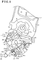
- FIG. 1 illustrates an exploded perspective view of the vehicle seat apparatus according to the first embodiment
- FIG. 2 illustrates a side view indicating a seating state according to the first embodiment
- FIG. 3 illustrates a side view indicating a walk-in state and a restored state according to the first embodiment
- FIG. 4 illustrates a side view indicating a tilt-down state according to the first embodiment
- FIG. 5 illustrates a side view indicating a tilt-down operating performing state and a restored state
- FIG. 6 illustrates a side view indicating a seating state according to the second embodiment
- FIG. 8 illustrates a walk-in state according to the second embodiment
- FIG. 9 illustrates a side view indicating an entire vehicle seat apparatus according to the embodiments of the present invention.
- FIG. 1 illustrates a part of a vehicle seat apparatus 1 according to the present invention illustrated in FIG. 9 , specifically illustrates an exploded perspective view of the vehicle seat apparatus 1 , decomposed in a seat width direction.
- a vehicle seat apparatus 1 includes a lower arm 2 made of a board material so as to form a bone structure of a seat cushion and an upper arm 3 made of a board material so as to form a bone structure of a seat back.
- the upper arm 3 is supported by the lower arm 2 in a manner where the upper arm 3 rotates relative to a rotation axis O in a seat front-rear direction so that the seat back is tilted in a front-back direction of the seat.
- the lower arm 2 and the upper arm 3 are provided in pair at each side of the seat in a seat width direction (e.g., the right side and the left side of the seat).
- FIG. 1 illustrates the lower arm 2 and the upper arm 3 provided at the right side of the vehicle seat facing a front direction thereof.
- a reclining mechanism (not shown) is provided between the lower arm 2 and the upper arm 3 in order to adjust an angle of the seat back relative to the rotation axis O.
- a reclining stopper 5 which is made of a plate material is joined at below the upper arm 3 .
- a stopper portion 5 a is formed so as to protrude in a manner where it extends inward from the lower arm 2 in a seat width direction.
- a first stopper plate portion 3 a is formed at one side in a circumferential direction of the rotation axis O (at the side of a clockwise direction in FIG. 1 ) so as to protrude outward in a radial direction of the rotation axis O
- a second stopper plate portion 3 b is formed at the other side of a circumferential direction of the rotation axis O (at the side of a clockwise direction in FIG. 1 ) so as to protrude outward in a radial direction of the rotation axis O.
- the stopper portion 5 a is positioned on a rotation path of the first stopper plate portion 3 a and the second stopper plate portion 3 b .
- the first stopper plate portion 3 a regulates a rotational angle of the upper arm 3 relative to the lower arm 2 .
- the second stopper plate portion 3 b regulates a rotational angle of the upper arm 3 relative to the lower arm 2 when the seat back is rotated backward.
- a pressing portion 6 a is formed in a manner where it protrudes outward in a radial direction of the rotation axis O at between the first stopper plate portion 3 a and the second stopper plate portion 3 b so as to be distanced inward from the upper arm 3 in a seat width direction.
- a guide member 7 which is made of a plate material is joined at the circumference of the rotation axis O.
- a guide portion 7 a is formed so as to protrude outward in a radial direction of the rotation axis O. Specifically, the guide portion 7 a is distanced from the upper arm 3 further inward relative to the pressing portion 6 a in a seat width direction.
- the guide portion 7 a is provided at the side of the second stopper plate portion 3 b in a circumferential direction of the rotation axis O more closer to the second stopper plate portion 3 b than the pressing portion 6 a . Further, in a radial direction of the rotation axis O, a length of the guide portion 7 a is set to be shorter than a length of the pressing portion 6 a.
- a base member 11 is fixed by means of a fastening member such as a bolt and a nut at the inner surface of the lower arm 2 so as not to interfere with the reclining stopper 5 .
- the base member 11 includes a first base bracket 12 and a second base bracket 13 so as to be integral, and the first base bracket 12 and the second base bracket 13 are provided in pair in a seat width direction.
- the first base bracket 12 is provided at the inner surface of the lower arm 2 at which the reclining stopper 5 is joined, and the second base bracket 13 is positioned at an inner surface of the first base bracket 12 and fixed at the lower arm 2 .
- an attachment hole 12 a is formed in an approximately rectangular shape so as to open in a seat width direction, and a first stopper piece 12 b is formed at the first base bracket 12 in a plate shape so as to protrude upward.
- the first stopper piece 12 b is provided above the attachment hole 12 a and between the first stopper plate portion 3 a and the pressing portion 6 a in a seat width direction.
- an attachment hole 13 a and a second stopper piece 13 b are formed, an attachment hole 13 a formed so as to have an approximately rectangular shape cross section and open in a seat direction, and a second stopper piece 13 b formed in a plate shape so as to protrude upward.
- the second stopper piece 13 b is provided above the attachment hole 13 a at between the pressing portion 6 a and the guide portion 7 a in a seat width direction.
- the first stopper piece 12 b and the second stopper piece 13 b are provided so as to be spaced in a manner where the pressing portion 6 a is provided between the first stopper piece 12 b and the second stopper piece 13 b in a seat width direction at the central position therebetween.
- a cable supporting piece 13 c is formed at the second base bracket 13 so as to protrude in a seat width direction.
- a metal fitting 30 a of a cable 30 which is shown in FIG. 2 is supported.
- a sensor bracket 14 (e.g., serving as a bracket) made of a plate material is fixed at a central portion of an inner surface of the second base bracket 13 so as not to interfere with the attachment hole 13 a and the like.
- a stopper wall portion 14 a and a guide wall portion 14 b are formed at the sensor bracket 14 .
- the stopper wall portion 14 a protrudes inward from an inner surface of the second base bracket 13 in a seat width direction, and the guide wall portion 14 b is bent upward from the stopper wall portion 14 a .
- a long hole 15 and an engagement concave portion 15 a are formed at the guide wall portion 14 b .
- the long hole 15 extends in a seat front-rear direction, and the engagement concave portion 15 a is formed at one end of the long hole 15 so as to sharply concave upward.
- a flange 17 a is formed integrally with the hinge pin 17 in a manner where it protrudes radially outward relative to the hinge pin 17 .
- a main link 18 (e.g., serving as a first link) is supported at the central portion of the hinge pin 17 so as to be rotatable at a central portion of the hinge pin.
- the main link 18 is made of a plate material and formed in an arm shape.
- the main link 18 is allowed to smoothly rotate relative to the hinge pin 17 .
- the main link 18 is provided between the second stopper piece 13 b and the guide wall portion 14 b in a seat width direction.
- a sub link 19 (e.g., serving as a third link) fits the hinge pin 17 at an opposite side of the main link 18 in a manner where the hinge pin 17 is inserted into a hole formed on the sub link 19 so that the flange 17 a is sandwiched between a sub link 19 and the main link 18 .
- the sub link 19 is made of a plate material so as to be formed in a sector shape.
- a cable link 20 (e.g., serving as an operation link), which is made of a plate material fits the hinge pin 17 in a manner where the hinge pin 17 is penetrated through a hole formed on a cable link 20 .
- a washer 21 formed in a ring shape is attached at the end of the hinge pin 17 so that the sub link 19 and the cable link 20 is not pulled out of the hinge pin 17 .
- the sub link 19 and the cable link 20 are supported by the hinge pin 17 so as to be rotatable relative to the hinge pin 17 .
- the main link 18 , the sub link 19 and the cable link 20 are positioned so as to have a coaxial axis at the hinge pin 17 .
- the sub link 19 and a cable link 20 are provided in a manner where predetermined spaces are provided between the washer 21 and the flange 17 a so that the sub link 19 and the cable link 20 are allowed to rotate smoothly relative to the hinge pin 17 .
- a sensor link 23 (e.g., serving as a second link) is rotatably supported by the main link 18 at the opposite side of the walk-in stopper pin 22 in a manner where the sensor link 23 is coaxial to an axial of the walk-in stopper pin 22 .
- the sensor link 23 is made of a plate material and formed in an arm shape.
- a sensor pin 24 (e.g., serving as a pin) is provided so as to protrude from the side of the second base bracket 13 .
- the sensor pin 24 is provided so as to be inserted into the long hole 15 of the sensor bracket 14 .
- the sensor pin 24 is biased by means of a sensor spring 25 (e.g., serving as a biasing member), which is made of a coil spring, so as to contact an upper inner wall surface of the long hole 15 .
- a sensor spring 25 e.g., serving as a biasing member
- One end of the sensor spring 25 engages the main link 18
- the other end of the sensor spring 25 engages the sensor link 23 .
- the guide member 7 is provided in a manner where the guide portion 7 a thereof is positioned between the sensor bracket 14 and the sensor link 23 in a seat width direction.
- an engaging piece 18 a bending in a seat width direction is formed.
- the engaging piece 18 a is inserted into a long hole 19 a formed at the sub link 19 in a long shape extending so as to be in an arch shape.
- relative rotations between the main link 18 and the sub link 19 are limited in a manner where the engaging piece 18 a engages the inner wall surface of the long hole 19 a.
- a supporting piece 20 a At one end portion of the cable link 20 , a supporting piece 20 a , at which one end of the cable spring 16 is engaged, is formed. The other end of the cable spring 16 is engaged with the first base bracket 12 .
- a hook portion 20 b is formed at the other end portion of the cable link 20 .
- the hook portion 20 b is biased in a clockwise direction in the attached drawings relative to the hinge pin 17 so as to engage the stopper wall portion 14 a of the sensor bracket 14 .
- a regulating wall portion 20 c and a supporting piece 20 d are formed at the cable link 20 .
- the regulating wall portion 20 c is formed extending in a seat width direction so as to have a reversed approximate C-shape cross section.
- One end of a main spring 27 engages an end portion of the engaging piece 18 a that is inserted into the long hole 19 a , and the other end portion of the main spring 27 engages the supporting piece 20 d , which is formed below the regulating wall portion 20 c .
- the main link 18 is biased by the main spring 27 so as to rotate relative to the hinge pin 17 in an anticlockwise direction in the attached drawings.
- a long hole 20 e is formed at the regulating wall portion 20 c , and a ball shaped end portion 30 b , which is formed at one end of the cable 30 (shown in FIG. 2 ), engages the long hole 20 e .
- the cable 30 further includes at the other end thereof a metal fitting 30 a that is supported by the cable supporting piece 13 c .
- the long hole 20 e is formed so as to extend along the reversed C-shape of the regulating wall portion 20 c and bend at a lower end of the regulating wall portion 20 c in a U-shape, and further extend so as to continue an attachment hole 20 f where the end portion 30 b is attached to and detached from.
- the cable 30 is attached at the cable link 20 as follows. First, the end portion 30 b inserted into the attachment hole 20 f is moved downward along the long hole 20 e , and the further moved upward so as to engage the end portion of the long hole 20 e.
- the cable 30 is connected to a tilt-down operation lever, which is not shown in the drawings.
- an operation force is transmitted so that the end portion 30 b is pulled so as to rotate the cable link 20 in an anticlockwise direction against the biasing force applied thereto by the cable spring 16 .
- the main link 18 which is connected to the cable link 20 by means of the main spring 27 , is rotated in accordance with the rotation of the cable link 20 .
- An elastic force of the main spring 27 is set at a predetermined level at which the main spring 27 is not substantially deformed when the main link 18 is rotated in accordance with the rotation of the cable link 20 .
- FIG. 2 illustrates a side view indicating the vehicle seat apparatus that is in a seating state, in which a passenger normally seats thereon.
- FIG. 3 illustrates a side view of the vehicle seat apparatus after a walk-in operation is performed and a restore operation is performed.
- FIG. 4 illustrates a side view indicating the vehicle seat apparatus after a tilt-down operation is performed.
- FIG. 5 illustrates a side view indicating the vehicle seat apparatus during a tilt-down operation is performed and when the restored operation is performed.
- the seating state of the vehicle seat apparatus illustrated in FIG. 2 is also a walk-in standby state at which the seat back is ready to be tilted forward (rotating the upper arm 3 ) for the walk-in operation.
- the cable link 20 is positioned at and maintained by the base member 11 in a manner where the hook portion 20 b engages the stopper wall portion 14 a of the sensor bracket 14 by means of a biasing force of the cable spring 16 .
- the cable 30 is provided in a manner where the end portion 30 b thereof engaging the end portion of the long hole 20 e fits a corner formed at the upper portion of the regulating wall portion 20 c.
- the walk-in stopper pin 22 provided at the main link 18 is positioned on a rotation path of the pressing portion 6 a relative to the rotation axis O.
- the sensor pin 24 provided at the sensor link 23 is positioned at a central portion in a longitudinal direction of the long hole 15 , and the sensor pin 24 is biased by means of the sensor spring 25 so as to engage an upper inner surface of the long hole 15 .
- the rotational position of the main link 18 by which the seating state (walk-in standby state) is regulated is for setting a design reference position of the main link 18 .
- the design reference position at this point is set at a central position within an actuation range of the main link 18 in accordance with a moving range of the sensor pin 24 within the long hole 15 .
- the sub link 19 biased by the biasing means of the seat slide mechanism through the connecting link 26 is positioned in a manner where the engaging piece 18 a is located within the long hole 19 a at one side in a circumferential direction thereof (in a clockwise direction within the long hole 19 a in the attached drawings).
- the pressing portion 6 a is regulated by means of the walk-in stopper pin 22 so as not to rotate, and the upper arm 3 is maintained at a predetermined rotational position of the walk-in state.
- the seat back is maintained at a predetermined angle of the walk-in state.
- the main link 18 at which the walk-in stopper pin 22 is provided functions as a stopper when the walk-in operation is performed.
- the main link 18 makes the sub link 19 rotate in a clockwise direction in the attached drawings, against the biasing force applied thereto by the biasing means of the seat slide mechanism, in a manner where the engaging piece 18 a presses the inner wall surface of the long hole 19 a , in accordance with the rotation of the main link 18 in a clockwise direction in the attached drawings.
- the seat back is moved backward, and the upper arm 3 is rotated in a clockwise direction in the attached drawings relative to the rotation axis O.
- the main link 18 is rotated so as to be in the seating state in a manner where the walk-in stopper pin 22 follows the rotation of the pressing portion 6 a.
- the main link 18 is positioned and maintained in a manner where the engaging piece 18 a contacts the cable link stopper portion 20 g .
- the engaging piece 18 a disengages from the long hole 19 a , because a biasing force is applied to the sub link 19 by the biasing means of the seat slide mechanism, the sub link 19 is rotated so as to be in the seating state.
- the main link 18 connected to the cable link 20 by means of the main spring 27 make the sensor pin 24 formed at the sensor link 23 slide in the other direction (leftward in FIG. 2 ) within the long hole 15 so as to rotate together with the cable link 20 .
- the walk-in stopper pin 22 provided at the main link 18 moves so as to be out of the rotation path of the pressing portion 6 a relative to the rotation axis O.
- the guide portion 7 a exists between the sensor pin 24 and the engagement concave portion 15 a , the sensor pin 24 does not fit into the engagement concave portion 15 a .
- the main link 18 is still rotatable relative to the hinge pin 17 .
- the reclining mechanism is not unlocked. After the cable 30 is operated so as to be further pulled, the reclining mechanism is unlocked in accordance with the operation of the cable 30 .
- the walk-in stopper pin 22 is still positioned out of the rotation path of the pressing portion 6 a ; in other words, the walk-in operation has been canceled.
- the walk-in operation is switched to the tilt-down operation the cable link 20 by means of the cable link 20 through which the operation force is transmitted from the operation lever.
- the rotation of the stopper portion 5 a is limited in a manner where the first stopper plate portion 3 a contacts the stopper portion 5 a , as a result, the upper arm 3 is maintained at a predetermined position (a predetermined rotational position) of the tilt-down state.
- the seat back is maintained at a predetermined angle (predetermined angle position) at which the seat is greatly tilted forward so as to be in the tilt-down state.
- the walk-in stopper pin 22 and the sensor link 23 are provided in a manner where a central axis of the walk-in stopper pin 22 is coaxial to the rotational axis of the sensor link 23 , when the main link 18 is rotated so that move the walk-in stopper pin 22 is moved so as to be on the rotation path of the pressing member 6 or out of the rotation path of the pressing member 6 , the sensor link 23 is moved integrally with the main link 18 relative to the rotational axis that is coaxial to the central axis of the walk-in stopper pin 22 .
- a space required for allowing the rotation of the main link 18 integrally with the walk-in stopper pin 22 and the sensor link 23 may be provided intensively in the vicinity of its rotational axis.
- the vehicle seat apparatus occupies as little space as possible, and limitation of the actuation range in which the main link 18 actuates is reduced.
- the main link 18 , the sub link 19 and the cable link 20 are positioned in a manner where each rotational axis is provided so as to be coaxial, a space required for allowing the rotations of the main link 18 , the sub link 19 and the cable link 20 may be provided intensively in the vicinity of each rotational axis.
- the vehicle seat apparatus occupies as little space as possible.
- the main link 18 , the sub link 19 and the cable link 20 which are related to the walk-in operation and the tilt-down operation, are positioned in a manner where each rotational axis is provided so as to be coaxial, responsivity of the walk-in operation and the tilt-down operation can be improved.
- the flange 17 a of the hinge pin 17 is provided between the main link 18 and the sub link 19 so that the main link 18 , the sub link 19 and the cable link 20 are separated into two parts in an axial direction of the rotational axis; one includes the main link 18 and the other includes the sub link 19 and the cable link 20 .
- a space is provided between a link and a member, which are adjacent each other in an axial direction of the rotational axis, in order to reduce friction therebetween.
- the main link 18 , the sub link 19 and the cable link 20 are provided so as to overlap in an axial direction of the rotational axis, it is necessary to provide a space between the main link 18 and the sub link 19 and provide another space between the sub link 19 and the cable link 20 .
- the flange 17 a of the hinge pin 17 is provided between the main link 18 and the sub link 19 so that the main link 18 , the sub link 19 and the cable link 20 are separated into two parts, a total of the spaces provided therebetween in an axial direction of the rotational axis is reduced. Further, chances that an axial misalignment of each link, which is caused by the existences of the spaces, can be reduced.
- the design reference position of the main link 18 is set at the central position of the actuation range in which the main link 18 is actuated.
- the design reference position can be flexibly changed to any position within the actuation range of the main link 18 , for example by changing the shape of the hook portion 20 b of the cable link 20 that engages the stopper wall portion 14 a of the sensor bracket 14 .
- flexibility in design is enhanced, as a result, versatility to the vehicle seat apparatus 1 can be improved.
- components such as the main link 18 related to the walk-in operation and the tilt-down operation are integrated as a unit on the basis of the base member 11 .
- mountability to the lower arm 2 is improved.
- a Second embodiment according to the present invention will be explained in accordance with the attached drawings.
- a vehicle seat apparatus of the second embodiment has approximately the same configuration as that of the first embodiment. However, in the second embodiment, the seating state is explained as a tilt-down standby state.
- the same numerals as that of the first embodiment are used for the same components. The second embodiment will be explained focusing on the difference between the first embodiment and the second embodiment.
- FIG. 6 illustrates a side view of the vehicle seat apparatus according to the second embodiment when it is in a seating state, which is also a tilt-down standby state.
- a pressing member 41 made of a plate material is joined at circumference of the rotation axis O.
- a pressing portion 41 a is formed in a manner where it protrudes outward in a radial direction relative to the rotation axis O at between the first stopper plate portion 3 a and the second stopper plate portion 3 b so as to be distanced inward from the upper arm 3 in a seat width direction (near side in an orthogonal direction relative to FIG. 6 ).
- the guide member 42 made of a plate material is joined at circumference of the rotation axis O.
- a guide portion 42 a is formed at the guide member 42 so as to protrude outward in a radial direction of the rotation axis O in a manner where the guide portion 42 a is distanced from the upper arm 3 in a seat width direction further inward relative to the pressing portion 41 a.
- the guide portion 42 a is positioned at the side of the second stopper plate portion 3 b relative to the pressing portion 41 a .
- the length of the guide portion 42 a relative to the rotation axis O in a radial direction is set to be shorter than the length of the pressing portion 41 a relative to the rotation axis O in a radial direction.
- the pressing portion 41 a and the guide portion 42 a are formed in a manner where the rotation path of the pressing portion 41 a and the rotation path of the guide portion 42 a are not overlapped each other both in a radial direction and in a seat width direction.
- each of the pressing member 41 and the guide member 42 has an opening formed in a circle shape relative to the rotation axis O, and a reclining mechanism and a control shaft (not shown), by which an operation force is inputted in order to unlock the reclining mechanism, are connected to the opening.
- the base member 51 On the inner surface of the lower arm 2 , the base member 51 is fixed by means of fastening members such as a bolt and a nut. At the base member 51 , a stopper piece 51 a formed in a plate shape so as to protrude upward is formed. The stopper piece 51 a is provided between the first stopper plate portion 3 a and the pressing portion 41 a in a seat width direction. On the base member 51 , a cable supporting piece 51 b is formed so as to protrude in a seat width direction, and a metal fitting 52 a of the cable 52 is supported by the cable supporting piece 51 b.
- a hinge pin 55 is fixed in a manner where an axis line thereof extends in a seat width direction.
- a main link 56 (e.g., serving as a first link) made of a plate material so as to be formed in an arm shape is rotatably supported.
- the main link 56 is biased by means of a spring, which is not shown in the diagrams, so as to rotate in an anticlockwise direction in the drawings, and the main link 56 is positioned and maintained in a manner where it contacts the base member 51 .
- the hinge pin 55 is located below the stopper piece 51 a . Further, the main link 56 is provided between the stopper piece 51 a and the guide wall portion 53 a in a seat width direction.
- a sub link 57 made of a plate material so as to be formed in a sector shape is rotatably supported in a manner where it overlaps the main link 56 .
- the main link 56 and the sub link 57 are provided in a manner where each of the sub link 57 and the main link 56 has an coaxial rotational axis at the hinge pin 55 .
- a walk-in stopper pin 58 (e.g., serving as a stopper pin) is fixed, a walk-in stopper pin 58 formed in an approximately column shape in a manner where its central axis extends in a seat width direction.
- a length of the walk-in stopper pin 58 in an axial direction thereof is set in a manner where the walk-in stopper pin 58 contacts the stopper piece 51 a in accordance with the rotation of the main link 56 .
- the rotation of the main link 56 relative to the hinge pin 55 is regulated in a manner where the walk-in stopper pin 58 contacts the stopper piece 51 a.
- a sensor link 59 (e.g., serving as a second link), which is made of a plate material so as to be in an arm shape, is rotatably supported at the opposite side of the walk-in stopper pin 58 .
- a rotational axis of the sensor link 59 is coaxial to the axis of the walk-in stopper pin 58 .
- a sensor pin 60 is provided so as to protrude in a seat width direction.
- the sensor pin 60 is penetrated through the long hole 54 of the sensor bracket 53 from the side of the base member 51 .
- the sensor pin 60 is biased so as to contact the lower inner wall surface of the long hole 54 by means of the sensor spring, which is provided in a manner where one end thereof engages the main link 56 and the other end thereof engages the sensor link 59 .
- the guide portion 42 a of the guide member 42 is provided between the sensor bracket 53 and the sensor link 59 in a seat width direction.
- an engaging pin 61 formed so as to protrude in a seat width direction is fixed.
- the engaging pin 61 is penetrated through a long hole 57 a , which is formed at the sub link 57 so as to be in a arch shape extending relative to the hinge pin 55 .
- relative rotations of the main link 56 and the sub link 57 are regulated in a manner where the engaging pin 61 engages the inner wall surface of the long hole 57 a.
- an extending portion 57 b which is formed in an arm shape so as to extend outward in a radial direction of the sub link 57 , is formed.
- a connecting link 26 is connected so as to be rotatable.
- the sub link 57 presses the connecting link 26 in accordance with the rotation of the sub link 57 in a clockwise direction in the attached drawings relative to the hinge 55 , in order to unlock of the lock mechanism L of the seat slide mechanism.
- the sub link 57 is biased by means of a biasing means of the seat slide mechanism through the connecting link 26 so as to rotate relative to the hinge pin 55 in an anticlockwise direction.
- a hinge pin 62 is fixed below the hinge pin 55 , and at the hinge pin 62 , a cable link 63 , which is made of a plate material so as to be in an arm shape, is rotatably supported. At the end portion of the cable link 63 , a U-shaped engage piece 63 a is formed. Specifically, an engage pin 64 is formed at the main link 56 at the opposite side of the walk-in stopper pin 58 in a manner where a central axis of the engage pin 64 is coaxial to that of the walk-in stopper pin 58 , and the engage pin 64 engages the engage piece 63 a .
- a posture of the cable link 63 is regulated in a manner where the cable link 63 rotates relative to the hinge pin 62 in accordance with the rotation of the main link 56 relative to the hinge pin 55 .
- FIG. 6 illustrates a side view indicating a seating state, which is also a tilt-down standby state.
- FIG. 7 illustrates a side view indicating the walk-in standby state, and
- FIG. 8 illustrates a walk-in state.
- the main link 56 is positioned and maintained in a manner where the main link 56 is biased by means of the spring so as to contact the base member 51 .
- the walk-in stopper pin 58 provided at the main link 56 is positioned out of the rotation path of the pressing portion 41 a relative to the rotation axis O.
- the sensor pin 60 provided at the sensor link 59 is provided at one end of the long hole 54 in a longitudinal direction thereof (left end in FIG. 6 ), and the sensor pin 60 is biased by the above mentioned sensor spring so as to contact the lower inner wall surface of the long hole 54 .
- the rotational position of the main link 56 when the vehicle seat apparatus is in the seating state is for regulating the design reference position of the main link 56 .
- the design reference position of the main link 56 is set at one end of an actuation range of the main link 56 in accordance with the moving range of the sensor pin 60 within the long hole 54 .
- the sub link 57 to which the biasing force is applied by the biasing means of the seat slide mechanism through the connecting link 26 is provided in a manner where the engaging pin 61 is located at one end portion of the long hole 57 a in a circumferential direction (one end in an anticlockwise direction relative to the hinge pin 55 ).
- a posture of the cable link 63 which is connected to the main link 56 by means of the engage pin 64 , is regulated by means of the main link 56 .
- the walk-in operation lever is operated and an operation force is transmitted from the walk-in operation lever, and the end portion 52 b of the cable 52 is pulled, the cable link 63 is rotated in a clockwise direction in the attached drawings.
- the main link 56 connected to the cable link 63 by means of the engage pin 64 slides the sensor pin 60 within the long hole 54 toward the other end in a longitudinal direction thereof (right side in FIG. 6 ), and then the main link 56 is rotated integrally with the cable link 63 against the biasing force applied by the spring.
- the walk-in stopper pin 58 provided at the main link 56 moves on the rotational path of the pressing portion 41 a relative to the rotation axis O.
- the sensor pin 60 engages the engagement concave portion 54 a
- the rotation of the main link 56 is further allowed while the walk-in stopper pin 58 is located on the rotation path.
- the cable link 63 inputs the operation for switching from the tilt-down operation to the walk-in operation.
- the engaging pin 61 moves to the other end portion in a circumferential direction of the long hole 57 a of the sub link 57 (a clockwise direction side). After the walk-in stopper pin 58 is moved so as to be on the rotation path, the reclining mechanism is unlocked.
- the main link 56 rotates the sub link 57 in a clockwise direction in the attached drawings, against the biasing force applied by the biasing means of the seat slide mechanism, in a manner where the engaging pin 61 presses the inner wall surface of the long hole 57 a .
- the connecting link 26 connected to the sub link 57 is pressed forward, and the seat slide mechanism, which interlocks the rotation of the upper arm 3 , is unlocked, as a result, the seat is slid in a front direction.
- the sensor pin 60 engaging the engagement concave portion 54 a is guided by means of the guide portion 42 a in accordance with the rotation of the guide member 42 so as to be pushed off from the engagement concave portion 54 a , and then the main link 56 is positioned and maintained by contacting the base member 51 so as to be in a seating state as shown in FIG. 6 .
- the engaging pin 61 disengages the long hole 57 a , the sub link 57 restored to be in a seating state in a manner where a biasing force is applied to the sub link 27 by the biasing means of the seat slide mechanism.
- the walk-in stopper pin 58 and the sensor link 59 are provided in a manner where a central axis of the walk-in stopper pin 58 is coaxial to the rotational axis of the sensor link 59 , when the main link 56 is rotated so that the walk-in stopper pin 58 is moved so as to be on the rotation path of the pressing member 41 or out of the rotation path of the pressing member 41 , the sensor link 59 is moved integrally with the main link 56 relative to the rotational axis that is coaxial to the central axis of the walk-in stopper pin 58 .
- a space required for allowing the rotation of the main link 56 integrally with the walk-in stopper pin 58 and the sensor link 59 may be provided intensively in the vicinity of its rotational axis.
- the vehicle seat apparatus occupies as little space as possible, and limitation of the actuation range in which the main link 56 actuates is reduced.
- components such as the main link 56 related to the walk-in operation and the tilt-down operation are integrated as a unit on the basis of the base member 51 .
- mountability to the lower arm 2 is improved.
- the main link 56 , the sub link 57 and the cable link 63 may be positioned in a manner where the rotational axis (hinge pin 55 ) of the main link 56 , the rotational axis (hinge pin 55 ) of the sub link 57 is coaxial to the rotational axis (hinge pin 62 ) of the cable link 63 .
- the design reference position of the main link 56 may be set at a central position of the actuation range of the main link 56 in accordance with the moving range of the sensor pin 60 within the long hole 54 .
- the present invention may be applied to a vehicle seat apparatus provided at a front seat, or may apply to a vehicle seat apparatus provided at the second row of a vehicle which has three line seats like a mini-van.
Landscapes
- Engineering & Computer Science (AREA)
- Aviation & Aerospace Engineering (AREA)
- Transportation (AREA)
- Mechanical Engineering (AREA)
- Seats For Vehicles (AREA)
Abstract
Description
Claims (14)
Applications Claiming Priority (2)
| Application Number | Priority Date | Filing Date | Title |
|---|---|---|---|
| JP2005-307485 | 2005-10-21 | ||
| JP2005307485A JP4770389B2 (en) | 2005-10-21 | 2005-10-21 | Vehicle seat device |
Publications (2)
| Publication Number | Publication Date |
|---|---|
| US20070090674A1 US20070090674A1 (en) | 2007-04-26 |
| US7690728B2 true US7690728B2 (en) | 2010-04-06 |
Family
ID=37696461
Family Applications (1)
| Application Number | Title | Priority Date | Filing Date |
|---|---|---|---|
| US11/582,405 Expired - Fee Related US7690728B2 (en) | 2005-10-21 | 2006-10-18 | Vehicle seat apparatus |
Country Status (3)
| Country | Link |
|---|---|
| US (1) | US7690728B2 (en) |
| EP (1) | EP1777099B1 (en) |
| JP (1) | JP4770389B2 (en) |
Cited By (10)
| Publication number | Priority date | Publication date | Assignee | Title |
|---|---|---|---|---|
| US20090243362A1 (en) * | 2008-03-28 | 2009-10-01 | Lear Corporation | Vehicle seat assembly capable of performing easy entry with full memory |
| US20090315378A1 (en) * | 2008-06-24 | 2009-12-24 | Toyota Boshoku Kabushiki Kaisha | Switching mechanisms of vehicle seats |
| US20100176641A1 (en) * | 2007-06-29 | 2010-07-15 | Toyota Boshoku Kabushiki Kaisha | Vehicle seats |
| US20100207440A1 (en) * | 2007-06-29 | 2010-08-19 | Toyota Boshoku Kabushiki Kaisha | Vehicle seats |
| US20100236024A1 (en) * | 2007-09-17 | 2010-09-23 | Renault S.A.S. | Device for maintaining the hinge of an inclinable seat of a vehicle in an unlocked position |
| US20120062012A1 (en) * | 2010-09-10 | 2012-03-15 | Faurecia Automotive Seating, Inc. | Easy-entry seat-back release system for vehicle seat |
| US20130341953A1 (en) * | 2010-11-15 | 2013-12-26 | David A. White | One Touch Stow In Floor Seat Assembly With Automatic Lateral Displacement |
| US20140361594A1 (en) * | 2012-06-26 | 2014-12-11 | Johnson Controls Components GmbH & Co., KG | Fitting for a vehicle seat, and vehicle seat |
| US9010862B2 (en) * | 2012-10-23 | 2015-04-21 | Toyota Boshoku Kabushiki Kaisha | Seat frame structure |
| US20240116404A1 (en) * | 2021-06-25 | 2024-04-11 | Ts Tech Co., Ltd. | Vehicle seat |
Families Citing this family (14)
| Publication number | Priority date | Publication date | Assignee | Title |
|---|---|---|---|---|
| DE102006033554A1 (en) * | 2005-08-24 | 2007-03-01 | C. Rob. Hammerstein Gmbh & Co. Kg | Foldable seat for motor vehicle, has swivelable backrest formed with projection, which comes to stop at rear side of control area in support part upon forward tilting of backrest, where backrest is tilted together with swiveling of part |
| JP5169146B2 (en) * | 2007-10-30 | 2013-03-27 | アイシン精機株式会社 | Vehicle seat device |
| JP5119911B2 (en) * | 2007-12-26 | 2013-01-16 | トヨタ紡織株式会社 | Vehicle seat |
| JP5286832B2 (en) * | 2008-03-04 | 2013-09-11 | トヨタ紡織株式会社 | Vehicle seat |
| JP5207791B2 (en) * | 2008-03-24 | 2013-06-12 | テイ・エス テック株式会社 | Vehicle storage seat |
| US7871127B2 (en) * | 2008-08-01 | 2011-01-18 | Bae Industries, Inc. | Seat recliner/dump mechanism such as incorporated into a seatback slaved to a floor latch release |
| JP5655574B2 (en) * | 2011-01-07 | 2015-01-21 | アイシン精機株式会社 | Vehicle seat reclining device |
| FR2992912B1 (en) * | 2012-07-03 | 2014-07-11 | Renault Sa | SEAT BACK FOLDING DEVICE |
| JP6089848B2 (en) * | 2013-03-22 | 2017-03-08 | アイシン精機株式会社 | Vehicle seat reclining device |
| US10118509B2 (en) * | 2014-07-14 | 2018-11-06 | Aisin Seiki Kabushiki Kaisha | Seat reclining device for vehicle |
| DE102015204273A1 (en) * | 2015-03-10 | 2016-09-15 | Brose Fahrzeugteile Gmbh & Co. Kg, Coburg | Vehicle seat with easy-entry function |
| JP6867841B2 (en) * | 2017-03-28 | 2021-05-12 | シロキ工業株式会社 | Seat reclining device |
| US10308146B1 (en) * | 2018-01-25 | 2019-06-04 | Ford Global Technologies, Llc | Track release mechanism for a seating assembly |
| JP7056526B2 (en) * | 2018-11-16 | 2022-04-19 | トヨタ紡織株式会社 | Stopper device |
Citations (13)
| Publication number | Priority date | Publication date | Assignee | Title |
|---|---|---|---|---|
| US5927809A (en) * | 1996-12-09 | 1999-07-27 | Atoma International, Inc. | Easy entry seat with seat back lockout until full return |
| US6106067A (en) * | 1996-07-25 | 2000-08-22 | P.L. Porter Co., | Seat adjustment and dumping mechanism with memory adjustment coordinated with seat positioning |
| US6336679B1 (en) | 1998-01-28 | 2002-01-08 | Bertrand Faure Components Ltd. | Rotary recliner control mechanism for multifunction vehicle seat applications |
| JP2003182416A (en) | 2001-12-25 | 2003-07-03 | Aisin Seiki Co Ltd | Seat device |
| US6601921B1 (en) * | 2001-08-29 | 2003-08-05 | Fisher Dynamics Corporation | Seatback latch release mechanism with safety capture |
| US6910739B2 (en) * | 2003-08-27 | 2005-06-28 | Bae Industries, Inc. | Seat recliner mechanism incorporating rotatable seatback slaved to a floor latch release |
| US7134724B2 (en) * | 2003-09-25 | 2006-11-14 | Grupo Antolin-Ingenieria, S.A. | Rotation mechanism for sequential angular variation of a backrest |
| US7380885B2 (en) * | 2003-08-11 | 2008-06-03 | Brose Fahrzeugteile Gmbh & Co. Kg, Coburg | Motor vehicle seat |
| US7387333B2 (en) * | 2005-04-18 | 2008-06-17 | Johnson Controls Technology Company | Seat latch |
| US7393056B2 (en) * | 2005-05-11 | 2008-07-01 | Lear Corporation | Vehicle seat release assembly |
| US7434883B2 (en) * | 2004-01-20 | 2008-10-14 | Faurecia Autositze Gmbh & Co. Kg | Vehicle seat |
| US7478882B2 (en) * | 2003-04-10 | 2009-01-20 | Brose Fahrzeugteile Gmbh & Co. Kg, Coburg | Motor vehicle seat |
| US7503099B2 (en) * | 2005-10-25 | 2009-03-17 | Fisher Dynamics Corporation | Memory mechanism for an adjustment mechanism |
Family Cites Families (3)
| Publication number | Priority date | Publication date | Assignee | Title |
|---|---|---|---|---|
| JP2003341392A (en) * | 2002-05-29 | 2003-12-03 | Daihatsu Motor Co Ltd | Seat unit for automobile |
| JP3798356B2 (en) * | 2002-10-09 | 2006-07-19 | トヨタ車体株式会社 | Vehicle seat |
| JP4064331B2 (en) * | 2003-10-14 | 2008-03-19 | 本田技研工業株式会社 | Seat adjuster device |
-
2005
- 2005-10-21 JP JP2005307485A patent/JP4770389B2/en not_active Expired - Fee Related
-
2006
- 2006-10-10 EP EP06122018.2A patent/EP1777099B1/en not_active Ceased
- 2006-10-18 US US11/582,405 patent/US7690728B2/en not_active Expired - Fee Related
Patent Citations (15)
| Publication number | Priority date | Publication date | Assignee | Title |
|---|---|---|---|---|
| US6106067A (en) * | 1996-07-25 | 2000-08-22 | P.L. Porter Co., | Seat adjustment and dumping mechanism with memory adjustment coordinated with seat positioning |
| US5927809A (en) * | 1996-12-09 | 1999-07-27 | Atoma International, Inc. | Easy entry seat with seat back lockout until full return |
| US6336679B1 (en) | 1998-01-28 | 2002-01-08 | Bertrand Faure Components Ltd. | Rotary recliner control mechanism for multifunction vehicle seat applications |
| JP2002501852A (en) | 1998-01-28 | 2002-01-22 | バートランド・フォーレ・コンポーネンツ・リミテッド | Rotary recliner control mechanism for multifunctional vehicle seats |
| US6601921B1 (en) * | 2001-08-29 | 2003-08-05 | Fisher Dynamics Corporation | Seatback latch release mechanism with safety capture |
| US6799801B2 (en) * | 2001-12-25 | 2004-10-05 | Aisin Seiki Kabushiki Kaisha | Seat device |
| JP2003182416A (en) | 2001-12-25 | 2003-07-03 | Aisin Seiki Co Ltd | Seat device |
| US7478882B2 (en) * | 2003-04-10 | 2009-01-20 | Brose Fahrzeugteile Gmbh & Co. Kg, Coburg | Motor vehicle seat |
| US7380885B2 (en) * | 2003-08-11 | 2008-06-03 | Brose Fahrzeugteile Gmbh & Co. Kg, Coburg | Motor vehicle seat |
| US6910739B2 (en) * | 2003-08-27 | 2005-06-28 | Bae Industries, Inc. | Seat recliner mechanism incorporating rotatable seatback slaved to a floor latch release |
| US7134724B2 (en) * | 2003-09-25 | 2006-11-14 | Grupo Antolin-Ingenieria, S.A. | Rotation mechanism for sequential angular variation of a backrest |
| US7434883B2 (en) * | 2004-01-20 | 2008-10-14 | Faurecia Autositze Gmbh & Co. Kg | Vehicle seat |
| US7387333B2 (en) * | 2005-04-18 | 2008-06-17 | Johnson Controls Technology Company | Seat latch |
| US7393056B2 (en) * | 2005-05-11 | 2008-07-01 | Lear Corporation | Vehicle seat release assembly |
| US7503099B2 (en) * | 2005-10-25 | 2009-03-17 | Fisher Dynamics Corporation | Memory mechanism for an adjustment mechanism |
Cited By (19)
| Publication number | Priority date | Publication date | Assignee | Title |
|---|---|---|---|---|
| US20100176641A1 (en) * | 2007-06-29 | 2010-07-15 | Toyota Boshoku Kabushiki Kaisha | Vehicle seats |
| US20100207440A1 (en) * | 2007-06-29 | 2010-08-19 | Toyota Boshoku Kabushiki Kaisha | Vehicle seats |
| US7857392B2 (en) * | 2007-06-29 | 2010-12-28 | Toyota Boshuku Kabushiki Kaisha | Vehicle seats |
| US7922251B2 (en) * | 2007-06-29 | 2011-04-12 | Toyota Boshoku Kabushiki Kaisha | Vehicle seats |
| US8430455B2 (en) * | 2007-09-17 | 2013-04-30 | Renault S.A.S. | Device for maintaining the hinge of an inclinable seat of a vehicle in an unlocked position |
| US20100236024A1 (en) * | 2007-09-17 | 2010-09-23 | Renault S.A.S. | Device for maintaining the hinge of an inclinable seat of a vehicle in an unlocked position |
| US20090243362A1 (en) * | 2008-03-28 | 2009-10-01 | Lear Corporation | Vehicle seat assembly capable of performing easy entry with full memory |
| US8141954B2 (en) * | 2008-06-24 | 2012-03-27 | Toyota Boshoku Kabushiki Kaisha | Switching mechanisms of vehicle seats |
| US20090315378A1 (en) * | 2008-06-24 | 2009-12-24 | Toyota Boshoku Kabushiki Kaisha | Switching mechanisms of vehicle seats |
| US20120062012A1 (en) * | 2010-09-10 | 2012-03-15 | Faurecia Automotive Seating, Inc. | Easy-entry seat-back release system for vehicle seat |
| US8690251B2 (en) * | 2010-09-10 | 2014-04-08 | Faurecia Automotive Seating, Llc | Easy-entry seat-back release system for vehicle seat |
| US9573494B2 (en) | 2010-09-10 | 2017-02-21 | Faurecia Automotive Seating, Llc | Easy-entry seat-back release system for vehicle seat |
| US20130341953A1 (en) * | 2010-11-15 | 2013-12-26 | David A. White | One Touch Stow In Floor Seat Assembly With Automatic Lateral Displacement |
| US8864209B2 (en) * | 2010-11-15 | 2014-10-21 | Magna Seating Inc. | One touch stow in floor seat assembly with automatic lateral displacement |
| US20140361594A1 (en) * | 2012-06-26 | 2014-12-11 | Johnson Controls Components GmbH & Co., KG | Fitting for a vehicle seat, and vehicle seat |
| US9371016B2 (en) * | 2012-06-26 | 2016-06-21 | Johnson Controls Components Gmbh & Co. Kg | Fitting for a vehicle seat, and vehicle seat |
| US9010862B2 (en) * | 2012-10-23 | 2015-04-21 | Toyota Boshoku Kabushiki Kaisha | Seat frame structure |
| US20240116404A1 (en) * | 2021-06-25 | 2024-04-11 | Ts Tech Co., Ltd. | Vehicle seat |
| US12496938B2 (en) * | 2021-06-25 | 2025-12-16 | Ts Tech Co., Ltd. | Vehicle seat |
Also Published As
| Publication number | Publication date |
|---|---|
| JP4770389B2 (en) | 2011-09-14 |
| EP1777099A2 (en) | 2007-04-25 |
| EP1777099B1 (en) | 2018-12-05 |
| JP2007112351A (en) | 2007-05-10 |
| US20070090674A1 (en) | 2007-04-26 |
| EP1777099A3 (en) | 2017-12-20 |
Similar Documents
| Publication | Publication Date | Title |
|---|---|---|
| US7690728B2 (en) | Vehicle seat apparatus | |
| US8360497B2 (en) | Lock mechanism for electric retractable seat for vehicle | |
| US8038198B2 (en) | Vehicle seats | |
| US9022479B2 (en) | Seat mechanism with easy-entry feature | |
| KR100895956B1 (en) | Seat adjustment for vehicle | |
| US4626028A (en) | Seat for vehicles | |
| US20050052062A1 (en) | Seat device | |
| US9180798B2 (en) | Vehicle lock | |
| US7686389B2 (en) | Seat apparatus for vehicle | |
| EP2293959B1 (en) | Seat | |
| US7914062B2 (en) | Lock apparatus for vehicle seat | |
| US7878592B2 (en) | Seat apparatus for vehicle | |
| JP4143264B2 (en) | Intermediate position memory sheet for easy access | |
| US20070138854A1 (en) | Folding recliner of seat for vehicles | |
| US8939511B2 (en) | Lock mechanism for automobile rear seat | |
| US20080088167A1 (en) | Seat reclining apparatus for vehicle | |
| US20020125757A1 (en) | Vehicle seat provided with a fold-down back | |
| US7588293B2 (en) | Vehicle walk-in device | |
| JP4064331B2 (en) | Seat adjuster device | |
| US7017994B2 (en) | Motor vehicle seat | |
| US20200056409A1 (en) | Lock device for vehicles | |
| US20180141473A1 (en) | Vehicle seat | |
| JP4430602B2 (en) | Vehicle seat device | |
| KR100559464B1 (en) | Reclining device for car seat | |
| JP4460518B2 (en) | Vehicle seat device |
Legal Events
| Date | Code | Title | Description |
|---|---|---|---|
| AS | Assignment |
Owner name: AISIN SEIKI KABUSHIKI KAISHA,JAPAN Free format text: ASSIGNMENT OF ASSIGNORS INTEREST;ASSIGNORS:MIYAUCHI, YUKIE;NIIMI, NAOKI;MAEDA, KENJI;REEL/FRAME:018437/0205 Effective date: 20061013 Owner name: AISIN SEIKI KABUSHIKI KAISHA, JAPAN Free format text: ASSIGNMENT OF ASSIGNORS INTEREST;ASSIGNORS:MIYAUCHI, YUKIE;NIIMI, NAOKI;MAEDA, KENJI;REEL/FRAME:018437/0205 Effective date: 20061013 |
|
| FEPP | Fee payment procedure |
Free format text: PAYOR NUMBER ASSIGNED (ORIGINAL EVENT CODE: ASPN); ENTITY STATUS OF PATENT OWNER: LARGE ENTITY |
|
| STCF | Information on status: patent grant |
Free format text: PATENTED CASE |
|
| FPAY | Fee payment |
Year of fee payment: 4 |
|
| MAFP | Maintenance fee payment |
Free format text: PAYMENT OF MAINTENANCE FEE, 8TH YEAR, LARGE ENTITY (ORIGINAL EVENT CODE: M1552) Year of fee payment: 8 |
|
| FEPP | Fee payment procedure |
Free format text: MAINTENANCE FEE REMINDER MAILED (ORIGINAL EVENT CODE: REM.); ENTITY STATUS OF PATENT OWNER: LARGE ENTITY |
|
| LAPS | Lapse for failure to pay maintenance fees |
Free format text: PATENT EXPIRED FOR FAILURE TO PAY MAINTENANCE FEES (ORIGINAL EVENT CODE: EXP.); ENTITY STATUS OF PATENT OWNER: LARGE ENTITY |
|
| STCH | Information on status: patent discontinuation |
Free format text: PATENT EXPIRED DUE TO NONPAYMENT OF MAINTENANCE FEES UNDER 37 CFR 1.362 |
|
| FP | Lapsed due to failure to pay maintenance fee |
Effective date: 20220406 |