US7688171B2 - Transformer and rectifier circuit using such transformer - Google Patents
Transformer and rectifier circuit using such transformer Download PDFInfo
- Publication number
- US7688171B2 US7688171B2 US12/199,947 US19994708A US7688171B2 US 7688171 B2 US7688171 B2 US 7688171B2 US 19994708 A US19994708 A US 19994708A US 7688171 B2 US7688171 B2 US 7688171B2
- Authority
- US
- United States
- Prior art keywords
- dimensional conductive
- winding frame
- transformer according
- conductive pieces
- transformer
- Prior art date
- Legal status (The legal status is an assumption and is not a legal conclusion. Google has not performed a legal analysis and makes no representation as to the accuracy of the status listed.)
- Active
Links
Images


Classifications
-
- H—ELECTRICITY
- H01—ELECTRIC ELEMENTS
- H01F—MAGNETS; INDUCTANCES; TRANSFORMERS; SELECTION OF MATERIALS FOR THEIR MAGNETIC PROPERTIES
- H01F27/00—Details of transformers or inductances, in general
- H01F27/28—Coils; Windings; Conductive connections
- H01F27/32—Insulating of coils, windings, or parts thereof
- H01F27/324—Insulation between coil and core, between different winding sections, around the coil; Other insulation structures
- H01F27/325—Coil bobbins
-
- H—ELECTRICITY
- H01—ELECTRIC ELEMENTS
- H01F—MAGNETS; INDUCTANCES; TRANSFORMERS; SELECTION OF MATERIALS FOR THEIR MAGNETIC PROPERTIES
- H01F27/00—Details of transformers or inductances, in general
- H01F27/28—Coils; Windings; Conductive connections
- H01F27/2866—Combination of wires and sheets
-
- H—ELECTRICITY
- H01—ELECTRIC ELEMENTS
- H01F—MAGNETS; INDUCTANCES; TRANSFORMERS; SELECTION OF MATERIALS FOR THEIR MAGNETIC PROPERTIES
- H01F27/00—Details of transformers or inductances, in general
- H01F27/40—Structural association with built-in electric component, e.g. fuse
-
- H—ELECTRICITY
- H02—GENERATION; CONVERSION OR DISTRIBUTION OF ELECTRIC POWER
- H02M—APPARATUS FOR CONVERSION BETWEEN AC AND AC, BETWEEN AC AND DC, OR BETWEEN DC AND DC, AND FOR USE WITH MAINS OR SIMILAR POWER SUPPLY SYSTEMS; CONVERSION OF DC OR AC INPUT POWER INTO SURGE OUTPUT POWER; CONTROL OR REGULATION THEREOF
- H02M7/00—Conversion of ac power input into dc power output; Conversion of dc power input into ac power output
- H02M7/003—Constructional details, e.g. physical layout, assembly, wiring or busbar connections
-
- H—ELECTRICITY
- H01—ELECTRIC ELEMENTS
- H01F—MAGNETS; INDUCTANCES; TRANSFORMERS; SELECTION OF MATERIALS FOR THEIR MAGNETIC PROPERTIES
- H01F27/00—Details of transformers or inductances, in general
- H01F27/40—Structural association with built-in electric component, e.g. fuse
- H01F2027/408—Association with diode or rectifier
-
- H—ELECTRICITY
- H01—ELECTRIC ELEMENTS
- H01F—MAGNETS; INDUCTANCES; TRANSFORMERS; SELECTION OF MATERIALS FOR THEIR MAGNETIC PROPERTIES
- H01F27/00—Details of transformers or inductances, in general
- H01F27/34—Special means for preventing or reducing unwanted electric or magnetic effects, e.g. no-load losses, reactive currents, harmonics, oscillations, leakage fields
Definitions
- the present invention relates to a transformer, and more particularly to a transformer having enhanced heat-dissipating efficiency, reduced cost and small size.
- the present invention also relates to a rectifier circuit having such a transformer.
- Switching power converters are used in a wide variety of applications to convert an unregulated power source into various regulated voltage levels by using several switches.
- a switching DC/DC power converter is used to convert DC power at one voltage level into other regulated DC voltage levels.
- Such a switching DC/DC power converter usually has a rectifier circuit for rectifying and filtering the input power.
- the rectifier circuit with low voltage but high output current has become a potential candidate to replace the conventional rectifier circuit.
- a well-known current-doubler rectifier (CDR) circuit has been proposed for use in high frequency DC/DC converter applications.
- the conventional current-doubler rectifier circuit has separate magnetic components, namely a transformer and at least one inductor.
- a coil is wound around a magnetic core assembly to form as a secondary winding assembly. Since the coil is very thin, its surface area is too small and thus the heat-dissipating efficiency of the transformer is unsatisfied. Since the rectifier circuit needs high output current, a great amount of heat will be generated during operation of the DC/DC converter. The drawback of using the coil as the secondary winding assembly becomes more serious if the output current is increased.
- a transformer in accordance with an aspect of the present invention, there is provided a transformer.
- the transformer includes a primary winding coil, a winding frame member, multiple first three-dimensional conductive pieces, a second three-dimensional conductive piece, a magnetic core assembly and a fixing plate.
- the winding frame member includes a first winding frame and a second winding frame for winding the primary winding coil thereon.
- the first three-dimensional conductive pieces are respectively sheathed around the first winding frame and the second winding frame of the winding frame member.
- the second three-dimensional conductive piece is arranged between the first three-dimensional conductive pieces.
- the magnetic core assembly is partially embedded into the first three-dimensional conductive pieces, the first winding frame, the second winding frame and the second three-dimensional conductive piece.
- the fixing plate is connected with the first three-dimensional conductive pieces and the second three-dimensional conductive piece so as to fix the first three-dimensional conductive pieces and the second three-dimensional conductive piece.
- a rectifier circuit in accordance with another aspect of the present invention, there is provided a rectifier circuit.
- the rectifier circuit includes a transformer of the present invention and an output capacitor.
- the output capacitor is electrically connected with the second three-dimensional conductive piece of the transformer.
- FIG. 1 is a schematic exploded view of a transformer according to a first preferred embodiment of the present invention
- FIG. 2 is a schematic assembled view of the transformer of FIG. 1 , which is mounted in a circuit board;
- FIG. 3 is a schematic perspective view illustrating a variation of the second three-dimensional conductive piece
- FIG. 4 is a schematic circuit block diagram of a DC/DC power converter using the transformer shown in FIG. 1 ;
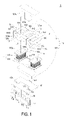
- FIG. 5 is a schematic exploded view of a transformer according to a second preferred embodiment of the present invention.
- FIG. 6 is a schematic assembled view of the transformer of FIG. 5 , which is mounted in a circuit board.
- FIG. 1 is a schematic exploded view of a transformer according to a first preferred embodiment of the present invention.
- FIG. 2 is a schematic assembled view of the transformer of FIG. 1 , which is mounted in a circuit board. Please refer to FIGS. 1 and 2 .
- the transformer 1 of the present invention may be used in a current-doubler rectifier circuit as shown in FIG. 4 .
- the transformer 1 principally comprises a primary winding coil 10 , a winding frame member 11 , a magnetic core assembly 12 , multiple first three-dimensional conductive pieces 13 , a second three-dimensional conductive piece 14 and a fixing plate 15 .
- the primary winding coil 10 is wound around the winding frame member 11 .
- the winding frame member 11 comprises two separate winding frames 110 and 111 .
- first winding frame 110 and the second winding frame 111 have respective central channels 110 a and 111 a such that the magnetic core assembly 12 may be partially embedded into the central channels 110 a and 111 a .
- first winding frame 110 and the second winding frame 111 are integrally formed.
- the primary winding coil 10 is enclosed by a tape (not shown) so as to isolate the primary winding coil 10 .
- the first three-dimensional conductive pieces 13 collectively define a secondary winding assembly of the transformer 1 .
- the first three-dimensional conductive pieces 13 are sheathed around the first winding frame 110 and the second winding frame 111 of the winding frame member 11 .
- the first winding frame 110 and the second winding frame 111 are received within the internal portions of the first three-dimensional conductive pieces 13 .
- Each of the first three-dimensional conductive pieces 13 is formed by turning a copper slice for multi-loops.
- a first three-dimensional conductive piece 13 is a three-dimensional structure comprising a first main body 130 , a first connecting part 131 , a second connecting part 132 and a first receiving part 133 .
- the first receiving part 133 is used to accommodate the first winding frame 110 or the second winding frame 111 of the winding frame member 11 .
- the first connecting part 131 is extended downwardly from a lower terminal of the first main body 130 and parallel with the length direction of the first receiving part 133 .
- the second connecting part 132 is extended horizontally and externally from an upper terminal of the first main body 130 .
- the first connecting part 131 and the second connecting part 132 are not coplanar.
- each of the first three-dimensional conductive pieces 13 is turned for two loops such that a gap is formed between these two loops.
- each of the first three-dimensional conductive pieces 13 may be turned for more than two loops.
- the second three-dimensional conductive piece 14 is turned for two or more loops.
- the magnetic core assembly 12 of the transformer 1 includes a first magnetic part 121 and a second magnetic part 122 , which are cooperatively formed as an EI-type core assembly.
- the first magnetic part 121 (E-type) and the second magnetic part 122 (I-type) are disposed on opposite sides of the winding frame member 11 and the first three-dimensional conductive pieces 13 .
- two leg parts 121 a of the first magnetic part 121 are embedded into the central channel 110 a of the first winding frame 110 and the central channel 111 a of the second winding frame 111 .
- the primary winding coil 10 and the first three-dimensional conductive piece 13 interact with the magnetic core assembly 12 to achieve the purpose of voltage regulation.
- the second three-dimensional conductive piece 14 is arranged between the multiple first three-dimensional conductive pieces 13 .
- the middle part 121 b of the first magnetic part 121 is embedded into the second receiving part 143 of the second three-dimensional conductive piece 14 .
- the second three-dimensional conductive piece 14 interacts with the middle part 121 b of the first magnetic part 121 to achieve the purpose of an inductor.
- the second three-dimensional conductive piece 14 is formed by turning a copper slice for multi-loops.
- the second three-dimensional conductive piece 14 is a three-dimensional structure comprising a second main body 140 , a third connecting part 141 (as shown in FIG. 2 ), a fourth connecting part 142 and a second receiving part 143 (as shown in FIG.
- the second receiving part 143 is defined by enclosing the second main body 140 for accommodating the middle part 121 b of the first magnetic part 121 .
- the third connecting part 141 is extended downwardly from a lower terminal of the second main body 140 and parallel with the length direction of the second receiving part 143 .
- the fourth connecting part 142 is extended from an upper edge of the second main body 140 and then extended downwardly such that the fourth connecting part 142 is substantially parallel with the third connecting part 141 and spaced from the third connecting part 141 by a gap.
- the second three-dimensional conductive piece 14 is turned for two loops. It is of course that the second three-dimensional conductive piece 14 may be turned for more than two loops as required.
- the fourth connecting part 142 is extended horizontally and externally from an upper terminal of the second main body 140 and then extended downwardly such that the fourth connecting part 142 is substantially parallel with the third connecting part 141 and spaced from the third connecting part 141 by a gap.
- the fixing plate 15 is disposed adjacent to the second magnetic part 122 of the magnetic core assembly 12 .
- the fixing plate 15 is made of conductive material such as copper.
- the fixing plate 15 has several perforations 151 corresponding to the first connecting parts 131 of the first three-dimensional conductive pieces 13 and the third connecting part 141 of the second three-dimensional conductive piece 14 . After the first connecting parts 131 and the third connecting part 141 are inserted into the perforations 151 , the first three-dimensional conductive pieces 13 and the second three-dimensional conductive piece 14 are fixed on the fixing plate 15 . As a result, the first three-dimensional conductive pieces 13 and the second three-dimensional conductive piece 14 are electrically coupled with each other through the fixing plate 15 .
- the locations of the perforations 151 and the shape of the fixing plate 15 may be varied as required.
- the first three-dimensional conductive pieces 13 and the second three-dimensional conductive piece 14 may be fixed on the fixing plate 15 by screwing or fastening.
- the transformer 1 further comprises at least one auxiliary plate 16 for facilitating supporting an electronic component 17 (e.g. a transistor or a diode) and removing heat generated from the electronic component 17 .
- the auxiliary plate 16 has several engaging holes 161 corresponding to the second connecting parts 132 of the first three-dimensional conductive pieces 13 . After the second connecting parts 132 of the first three-dimensional conductive pieces 13 are inserted into the engaging holes 161 of the auxiliary plate 16 , the auxiliary plate 16 is fixed on the first three-dimensional conductive pieces 13 .
- the auxiliary plate 16 is also made of conductive material such as copper. As a result, the electronic component 17 is electrically connected with the transformer through the auxiliary plate 16 .
- the transformer 1 is mounted on a circuit board 2 in an upright arrangement.
- the circuit board 2 has several slots (not shown) corresponding to the first connecting parts 131 of the first three-dimensional conductive pieces 13 and the fourth connecting part 142 of the second three-dimensional conductive piece 14 . After the first connecting parts 131 and the fourth connecting part 142 are inserted into corresponding slots, the transformer 1 is fixed on the circuit board 2 .
- each of the first three-dimensional conductive pieces 13 is formed by turning a copper slice for multi-loops, the surface area of the three-dimensional conductive piece 13 is very large. Due to the very large surface area of the three-dimensional conductive piece 13 , the transformer 1 may be operated at high output current with a desired heat-dissipating efficiency.
- FIG. 4 is a schematic circuit block diagram of a DC/DC power converter using the transformer shown in FIG. 1 .
- the DC/DC power converter 4 comprises an input terminal V IN , a switching circuit 41 , a control circuit 42 , a rectifier circuit 43 and an output terminal V OUT .
- a DC voltage is inputted into the DC/DC power converter 4 through the input terminal V IN .
- An example of the rectifier circuit includes but is not limited to a current-doubler rectifier (CDR) circuit.
- the switching circuit 41 is electrically connected to the input terminal V IN , the CDR circuit 43 and the control circuit 42 for receiving the DC voltage through the input terminal V IN .
- the switching circuit 41 Under control of the control circuit 42 , the switching circuit 41 provides a pulse width modulated voltage to the CDR circuit 43 .
- the switching circuit 41 comprises multiple switch elements (not shown).
- the switching circuit 41 comprises two switch elements to have a half-bridge topology or comprises four switch elements to have a full-bridge topology.
- the control circuit 42 is electrically connected to the switching circuit 41 , the CDR circuit 43 and the output terminal V OUT .
- the control circuit 42 may detect the voltage at the output terminal V OUT and control operations of the multiple switch elements of the switching circuit 41 .
- the CDR circuit 43 By the CDR circuit 43 , the pulse width modulated voltage issued from the switching circuit 41 is subject to voltage conversion, rectification and filtering and then outputted through the output terminal V OUT .
- the CDR circuit 43 comprises an output capacitor C, two rectifiers 431 , 432 and a transformer 1 .
- the transformer 1 has a configuration as shown in FIG. 1 .
- the transformer 1 comprises a primary winding coil 10 , a magnetic core assembly 12 , multiple first three-dimensional conductive pieces 13 and a second three-dimensional conductive piece 14 .
- the first three-dimensional conductive pieces 13 are used as a secondary winding assembly.
- the second three-dimensional conductive piece 14 is used as an inductor.
- the primary winding coil 10 is electrically connected to the switching circuit 41 for receiving the pulse width modulated voltage issued from the switching circuit 41 .
- the primary winding coil 10 , the first three-dimensional conductive piece 13 and the second three-dimensional conductive piece 14 interact with the magnetic core assembly 12 to achieve the purpose of voltage regulation.
- the first three-dimensional conductive pieces 13 are electrically connected to the rectifiers 431 and 432 and induced by the primary winding coil 10 , thereby generating an induced current.
- the induced current is also rectified by the rectifiers 431 and 432 .
- the second three-dimensional conductive piece 14 is electrically connected to the output capacitor C.
- the second three-dimensional conductive piece 14 and the output capacitor C collectively define a filter for filtering the regulated voltage issued from the transformer 1 .
- the filtered regulated voltage is outputted through the output terminal V OUT .
- the first three-dimensional conductive pieces 13 and the second three-dimensional conductive piece 14 are fixed on the fixing plate 15 , which is made of copper.
- the first three-dimensional conductive pieces 13 and the second three-dimensional conductive piece 14 are electrically coupled with each other through the fixing plate 15 . Therefore, as shown in FIG. 4 , the first three-dimensional conductive pieces 13 and the second three-dimensional conductive piece 14 are coupled to a node N.
- the rectifiers 431 and 432 include but are not limited to diodes or MOSFETs.
- the rectifiers 431 and 432 may be mounted on the auxiliary plate 16 along with the electronic component 17 .
- the second three-dimensional conductive piece 14 interacts with the magnetic core assembly 12 to achieve the purpose of an inductor, the second three-dimensional conductive piece 14 is used as an inductor of the CDR circuit 43 . That is, the second three-dimensional conductive piece 14 and the output capacitor C may collectively define a filter. Under this circumstance, no additional trace pattern is required to connect the transformer 1 and the inductor (i.e. the second three-dimensional conductive piece 14 ) so as to reduce power loss, cost and overall size. When the CDR circuit 43 is used in the DC/DC power converter 4 , the converting efficiency is satisfactory.
- FIG. 5 is a schematic exploded view of a transformer according to a second preferred embodiment of the present invention.
- FIG. 6 is a schematic assembled view of the transformer of FIG. 5 , which is mounted in a circuit board. Please refer to FIGS. 5 and 6 .
- the functions of the components included in the transformer of this embodiment are identical to those shown in FIGS. 1 and 2 , and are not redundantly described herein. Except for the auxiliary plate 16 and the electronic component 17 , the transformer 1 of this embodiment is mounted on the circuit board 2 in a horizontal arrangement in order to comply with different space configurations.
- the second connecting part 132 of the first three-dimensional conductive piece 13 is coplanar with the first connecting part 131 and parallel with the circuit board 2 .
- the fourth connecting part 142 of the second three-dimensional conductive piece 14 is perpendicular to the third connecting part 141 .
- the auxiliary plate 16 is fixed on the first three-dimensional conductive pieces 13 and adjacent to the first magnetic part 121 of the magnetic core assembly 12 .
- the transformer 1 is fixed on the circuit board 2 .
- the transformer and the rectifier circuit of the present invention have enhanced heat-dissipating efficiency because the surface area of the secondary winding assembly is increased by using the first three-dimensional conductive pieces as the secondary winding assembly. Moreover, since the second three-dimensional conductive piece interacts with the magnetic core assembly 12 to achieve the purpose of an inductor, no additional trace pattern is required to connect the transformer with the inductor. Consequently, the power loss, the cost and the size of the rectifier current are reduced. When the rectifier circuit is used in the DC/DC power converter, the converting efficiency is satisfactory.
Landscapes
- Engineering & Computer Science (AREA)
- Power Engineering (AREA)
- Dc-Dc Converters (AREA)
Abstract
Description
Claims (16)
Applications Claiming Priority (3)
| Application Number | Priority Date | Filing Date | Title |
|---|---|---|---|
| TW097122223A TWI324351B (en) | 2008-06-13 | 2008-06-13 | Transformer structure and rectifier circuit using the same |
| TW097122223 | 2008-06-13 | ||
| TW97122223A | 2008-06-13 |
Publications (2)
| Publication Number | Publication Date |
|---|---|
| US20090309684A1 US20090309684A1 (en) | 2009-12-17 |
| US7688171B2 true US7688171B2 (en) | 2010-03-30 |
Family
ID=41414203
Family Applications (1)
| Application Number | Title | Priority Date | Filing Date |
|---|---|---|---|
| US12/199,947 Active US7688171B2 (en) | 2008-06-13 | 2008-08-28 | Transformer and rectifier circuit using such transformer |
Country Status (2)
| Country | Link |
|---|---|
| US (1) | US7688171B2 (en) |
| TW (1) | TWI324351B (en) |
Cited By (3)
| Publication number | Priority date | Publication date | Assignee | Title |
|---|---|---|---|---|
| US20110254651A1 (en) * | 2010-04-19 | 2011-10-20 | Samsung Electro-Mechanics Co., Ltd. | Transformer and electronic apparatus including the same |
| USRE47423E1 (en) | 2015-04-23 | 2019-06-04 | Chicony Power Technology Co., Ltd. | Integrated power-converting module |
| US10770981B2 (en) | 2015-04-23 | 2020-09-08 | Chicony Power Technology Co., Ltd. | Voltage conversion module and bobbin |
Families Citing this family (19)
| Publication number | Priority date | Publication date | Assignee | Title |
|---|---|---|---|---|
| DE102011082046A1 (en) * | 2011-09-02 | 2013-03-07 | Schmidhauser Ag | Transformer and related manufacturing process |
| AT512064B1 (en) * | 2011-10-31 | 2015-11-15 | Fronius Int Gmbh | HIGH-FLOW TRANSFORMER, TRANSFORMER ELEMENT, CONTACT PLATE AND SECONDARY WINDING, AND METHOD FOR PRODUCING SUCH A HIGH-SPEED TRANSFORMER |
| FR3011713B1 (en) * | 2013-10-09 | 2017-06-23 | Valeo Systemes De Controle Moteur | ELECTRICAL MODULE, ELECTRICAL SYSTEM COMPRISING SUCH AN ELECTRIC MODULE, CORRESPONDING MANUFACTURING METHODS |
| TWI556273B (en) * | 2015-10-14 | 2016-11-01 | Yujing Technology Co Ltd | Resonant High Current Density Transformer |
| TWI619006B (en) * | 2016-04-14 | 2018-03-21 | 光寶電子(廣州)有限公司 | Power supply having high heat-dissipation circuit board assembly system and a high heat-dissipation circuit board assembly |
| CN113035523B (en) * | 2016-05-25 | 2022-05-31 | 台达电子企业管理(上海)有限公司 | Magnetic core structure and magnetic element |
| US20210050142A1 (en) * | 2016-05-25 | 2021-02-18 | Delta Electronics (Shanghai) Co., Ltd. | Power module and power device |
| US11728087B2 (en) | 2016-05-25 | 2023-08-15 | Delta Electronics (Shanghai) Co., Ltd | Core structure and magnetic device |
| US11901108B2 (en) * | 2016-05-25 | 2024-02-13 | Delta Electronics (Shanghai) Co., Ltd. | Power module and power device |
| TWI581280B (en) * | 2016-08-24 | 2017-05-01 | Yujing Technology Co Ltd | Improved Structure of Resonant High Current Density Transformer |
| CN109525099B (en) * | 2017-09-19 | 2021-01-05 | 群光电能科技股份有限公司 | Power supply conversion module |
| US11239026B2 (en) * | 2017-09-29 | 2022-02-01 | Illinois Tool Works Inc. | High-frequency transformers using solid wire for welding-type power supplies |
| US10354792B2 (en) | 2017-10-23 | 2019-07-16 | Sea Sonic Electronics Co., Ltd. | Transformer structure |
| JPWO2020003482A1 (en) * | 2018-06-29 | 2021-08-12 | 新電元工業株式会社 | Electronic device |
| FR3087043B1 (en) * | 2018-10-05 | 2020-11-20 | Brightloop | TRANSFORMATION DEVICE INCLUDING A TRANSFORMER AND ELECTRICAL COMPONENTS |
| WO2020168101A1 (en) * | 2019-02-13 | 2020-08-20 | Astronics Advanced Electronic Systems Corp. | Integrated transformer with low ac losses and impedance balanced interface |
| US11562854B1 (en) * | 2019-07-12 | 2023-01-24 | Bel Power Solutions Inc. | Dual slotted bobbin magnetic component with two-legged core |
| TWI760016B (en) | 2020-12-21 | 2022-04-01 | 大陸商光寶電子(廣州)有限公司 | Combined structure of transformer and circuit board as well as assembly method thereof |
| CN117524666A (en) * | 2022-07-27 | 2024-02-06 | 华为技术有限公司 | Planar transformer, power module and power module |
Citations (4)
| Publication number | Priority date | Publication date | Assignee | Title |
|---|---|---|---|---|
| US6211767B1 (en) * | 1999-05-21 | 2001-04-03 | Rompower Inc. | High power planar transformer |
| US20080180205A1 (en) * | 2007-01-31 | 2008-07-31 | Delta Electronics, Inc. | Transformer structure |
| US7414510B1 (en) * | 2007-12-17 | 2008-08-19 | Kuan Tech (Shenzhen) Co., Ltd. | Low-profile planar transformer |
| US7498921B1 (en) * | 2007-10-05 | 2009-03-03 | Acbel Polytech Inc. | Transformer and transformer assembly |
-
2008
- 2008-06-13 TW TW097122223A patent/TWI324351B/en active
- 2008-08-28 US US12/199,947 patent/US7688171B2/en active Active
Patent Citations (4)
| Publication number | Priority date | Publication date | Assignee | Title |
|---|---|---|---|---|
| US6211767B1 (en) * | 1999-05-21 | 2001-04-03 | Rompower Inc. | High power planar transformer |
| US20080180205A1 (en) * | 2007-01-31 | 2008-07-31 | Delta Electronics, Inc. | Transformer structure |
| US7498921B1 (en) * | 2007-10-05 | 2009-03-03 | Acbel Polytech Inc. | Transformer and transformer assembly |
| US7414510B1 (en) * | 2007-12-17 | 2008-08-19 | Kuan Tech (Shenzhen) Co., Ltd. | Low-profile planar transformer |
Cited By (5)
| Publication number | Priority date | Publication date | Assignee | Title |
|---|---|---|---|---|
| US20110254651A1 (en) * | 2010-04-19 | 2011-10-20 | Samsung Electro-Mechanics Co., Ltd. | Transformer and electronic apparatus including the same |
| US8299886B2 (en) * | 2010-04-19 | 2012-10-30 | Samsung Electro-Mechanics Co., Ltd. | Transformer and electronic apparatus including the same |
| USRE47423E1 (en) | 2015-04-23 | 2019-06-04 | Chicony Power Technology Co., Ltd. | Integrated power-converting module |
| US10770981B2 (en) | 2015-04-23 | 2020-09-08 | Chicony Power Technology Co., Ltd. | Voltage conversion module and bobbin |
| US10951123B2 (en) | 2015-04-23 | 2021-03-16 | Chicony Power Technology Co.. Ltd. | Power conversion system |
Also Published As
| Publication number | Publication date |
|---|---|
| US20090309684A1 (en) | 2009-12-17 |
| TW200952002A (en) | 2009-12-16 |
| TWI324351B (en) | 2010-05-01 |
Similar Documents
| Publication | Publication Date | Title |
|---|---|---|
| US7688171B2 (en) | Transformer and rectifier circuit using such transformer | |
| US7542316B2 (en) | Switching power supply unit | |
| US10297379B2 (en) | Integrated transformers and coupled inductors and associated systems and methods | |
| US6714428B2 (en) | Combined transformer-inductor device for application to DC-to-DC converter with synchronous rectifier | |
| US10951123B2 (en) | Power conversion system | |
| US6175219B1 (en) | Booster type converter with low power loss | |
| US8188830B2 (en) | Transformer and switching power supply unit | |
| US20180197673A1 (en) | Integrated Magnetic Component and Switched Mode Power Converter | |
| US10381914B2 (en) | Integrated transformer | |
| KR101279071B1 (en) | Energy transfer element and converter including thereof | |
| JP5979210B2 (en) | Power supply | |
| CN113950727A (en) | Stacked matrix transformer | |
| JP5240529B2 (en) | Switching power supply | |
| USRE47423E1 (en) | Integrated power-converting module | |
| KR101318425B1 (en) | Energy transfer element and converter including thereof | |
| JP2017079545A (en) | Insulation type power conversion device | |
| KR102221510B1 (en) | Transformer with improved and efficient heat discharge function | |
| KR102144616B1 (en) | Isolation dc-dc converter using coupled-inductor | |
| JP5451860B1 (en) | Switching power supply | |
| JP2000341951A (en) | Switching power supply unit | |
| US20230260690A1 (en) | Inductor Mountable on a Circuit Board | |
| KR200381869Y1 (en) | output module for a switching mode power supply | |
| JP2006211877A (en) | Switching power unit | |
| JP4520205B2 (en) | Switching power supply | |
| CN118039313A (en) | Flat-plate type transformer |
Legal Events
| Date | Code | Title | Description |
|---|---|---|---|
| AS | Assignment |
Owner name: DELTA ELECTRONICS, INC.,TAIWAN Free format text: ASSIGNMENT OF ASSIGNORS INTEREST;ASSIGNORS:TSAI, SHENG-NAN;WANG, SHUN-TAI;TSENG, HUNG-YU;AND OTHERS;REEL/FRAME:021456/0029 Effective date: 20080711 Owner name: DELTA ELECTRONICS, INC., TAIWAN Free format text: ASSIGNMENT OF ASSIGNORS INTEREST;ASSIGNORS:TSAI, SHENG-NAN;WANG, SHUN-TAI;TSENG, HUNG-YU;AND OTHERS;REEL/FRAME:021456/0029 Effective date: 20080711 |
|
| STCF | Information on status: patent grant |
Free format text: PATENTED CASE |
|
| FPAY | Fee payment |
Year of fee payment: 4 |
|
| MAFP | Maintenance fee payment |
Free format text: PAYMENT OF MAINTENANCE FEE, 8TH YEAR, LARGE ENTITY (ORIGINAL EVENT CODE: M1552) Year of fee payment: 8 |
|
| MAFP | Maintenance fee payment |
Free format text: PAYMENT OF MAINTENANCE FEE, 12TH YEAR, LARGE ENTITY (ORIGINAL EVENT CODE: M1553); ENTITY STATUS OF PATENT OWNER: LARGE ENTITY Year of fee payment: 12 |