US76730A - Ber-ffard demmin g - Google Patents
Ber-ffard demmin g Download PDFInfo
- Publication number
- US76730A US76730A US76730DA US76730A US 76730 A US76730 A US 76730A US 76730D A US76730D A US 76730DA US 76730 A US76730 A US 76730A
- Authority
- US
- United States
- Prior art keywords
- saw
- frame
- lever
- ffard
- demmin
- Prior art date
- Legal status (The legal status is an assumption and is not a legal conclusion. Google has not performed a legal analysis and makes no representation as to the accuracy of the status listed.)
- Expired - Lifetime
Links
Images

Classifications
-
- B—PERFORMING OPERATIONS; TRANSPORTING
- B23—MACHINE TOOLS; METAL-WORKING NOT OTHERWISE PROVIDED FOR
- B23D—PLANING; SLOTTING; SHEARING; BROACHING; SAWING; FILING; SCRAPING; LIKE OPERATIONS FOR WORKING METAL BY REMOVING MATERIAL, NOT OTHERWISE PROVIDED FOR
- B23D49/00—Machines or devices for sawing with straight reciprocating saw blades, e.g. hacksaws
- B23D49/007—Jig saws, i.e. machine saws with a vertically reciprocating narrow saw blade chucked at both ends for contour cutting
-
- B—PERFORMING OPERATIONS; TRANSPORTING
- B23—MACHINE TOOLS; METAL-WORKING NOT OTHERWISE PROVIDED FOR
- B23D—PLANING; SLOTTING; SHEARING; BROACHING; SAWING; FILING; SCRAPING; LIKE OPERATIONS FOR WORKING METAL BY REMOVING MATERIAL, NOT OTHERWISE PROVIDED FOR
- B23D51/00—Sawing machines or sawing devices working with straight blades, characterised only by constructional features of particular parts; Carrying or attaching means for tools, covered by this subclass, which are connected to a carrier at both ends
- B23D51/16—Sawing machines or sawing devices working with straight blades, characterised only by constructional features of particular parts; Carrying or attaching means for tools, covered by this subclass, which are connected to a carrier at both ends of drives or feed mechanisms for straight tools, e.g. saw blades, or bows
- B23D51/162—Stored energy furnished drive in one direction
-
- Y—GENERAL TAGGING OF NEW TECHNOLOGICAL DEVELOPMENTS; GENERAL TAGGING OF CROSS-SECTIONAL TECHNOLOGIES SPANNING OVER SEVERAL SECTIONS OF THE IPC; TECHNICAL SUBJECTS COVERED BY FORMER USPC CROSS-REFERENCE ART COLLECTIONS [XRACs] AND DIGESTS
- Y10—TECHNICAL SUBJECTS COVERED BY FORMER USPC
- Y10T—TECHNICAL SUBJECTS COVERED BY FORMER US CLASSIFICATION
- Y10T83/00—Cutting
- Y10T83/687—By tool reciprocable along elongated edge
- Y10T83/704—With work-support and means to vary relationship between tool and work support
Definitions
- Figure Q an end elevation, showing the lower portion in section
- Figure 3 a front View of the upper end of 4the saw, and v t v Figure 4 a side view of the same, showing the upper part oi' theadjusting-apparatus in section.
- a new device is ⁇ adopted for adjusting the saw at any inclination to either side, for the purpose of bevcl-sawinff, and anothcri'or regulating and adjusting the rake of the saw.
- a A represent the frame of the machine
- B the main wheel
- C the belt
- D the shaft, which directly operates the saw by 'means of a crank, IZ, and piston, ⁇ E.
- G is another iron plate, fastened across the frame under the sawiand containing a long curved slot, g, situated concave side up, as seen also in iig. 2.
- H is a stout iron yoke-frame, pivoted to the plate F at a point, 7L, at the centre of the circle of'which the curved slotf forms an are, in such a manner that,l as the yoke-frame H is sw'ung from side to side on its pivot, a stout bolt,l z', projecting from it into the curved slot, may traverse the whole length of the slot.
- the lower arm of the yoke H has a stout arm,lJ, extending down alongside of the' slotted iron plate G," and provided with a bolt or pin, e, which 'projects into the curved slot, and as the frame H is swung on its pivot L, traverses the whole length of the slot g.
- rlhe frame H is thus supported by its pivot L, and by the pins t' and e, projecting from it into and travelling back and forth in the curved slots g and Each pin which thus projects into the slot may be provided with a nut and screw, by which it can be firmly clamped to the plate F or Grat any point along the slot, and'may thus be made to hold the frame Hiirmly fixed in any given inclination, to 'the one side or the other of the machine.
- l I The yoke-frame H being thusadjusted, I x to the ends of it grooved-metallic plates' or blocks, K K, one above and one below the platform or table, L, upon which the work is sawed.
- the blocks m m' in.whie h the saw is hung, slide up 'andl down in vertical dove-tail grooves in the face ofthe metallic blocks K K.
- the lower slide, m' also runs through a dove-tail groove in the face side of the arm d', atits lower end, which gives addi tional steadiness to the motion of the saw. Below the latter groove it is connected to the pitman E by the pin e, as above described.
- the saw S being thus held by the sliding blocks m m', is kept at the proper tension by means of a. pivoted arm, M, Operated by a Spring, Z, which may be adjusted to diilercnt degrees of tension by setting it indifferent notches,a a a, upon the arm.
- a leather strap, T connects the lever with the sliding block m.
- N is a guide foot, adjustable at different heights by means of a set-screw, n, its object being to steady the board by holding it down close to the'surface of the table.
- O O are set-screws, by which the blocksKK can be adjusted at different elevations upon the yoke-frame I-I'.
- the rake of the saw is adjusted by attaching to thesliding blocl m, a. pivoted'lever, 0, to the lower end or which the saw is Afastened.
- a pin, p projects lfrom the slide m, above the pivot of the lever, through a holeiu the upper end of the lever, and a nut, n, screwing upon the end of the pin,serves to forcethe upper end ofthe lever in and throwthc lower end out, thereby producing any desired rake of the saw.
- the saw may be made to rake forward atany practicable inclination, or not to rake at all, asmay he desired.
- the vertical dove-tail grooves, in which the sliding blocks m m play, may be. made adjustable in width by making one of their wallsor'sides movable, and regulating it by set-screws.
- the plate F er G may be marked off as a graduated scale, by which the exact inclination of the saw will be indicated at once to the ey'e.
- the sliding block m may be made heavy, in order to act as a counterbalance to the spring Z, and render the motion of the sat even and steady.
Landscapes
- Engineering & Computer Science (AREA)
- Mechanical Engineering (AREA)
- Sawing (AREA)
Description
uitte gissen datent @ffice een Letters Patent No. 76,730, dated-April 14, 1868.
IMPROVEMENT IM senoLL's'AW MILLS.
@tige 'Sainte nient in lim tipa lettcts nteut nur mating ont at tige same.
TO ALL WHOM'IT MAY CONCER:
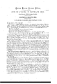
Beit known that I, BERNARD DEMMING, of Cleveland, in the county of Cuyahoga, and State ofgOh'io, have' invented a .newand improved Jig-Saw; and I do hereby declare the following to be a full, clear, and exact description of the same, suilicie'ntto enable those skilled in the artto which my invention appertains to make use ot' it, reference being had to the accompanying drawings, forming part l' this specification, in which Figure 1 is a side elevation,
Figure Q an end elevation, showing the lower portion in section,
Figure 3 a front View of the upper end of 4the saw, and v t v Figure 4 a side view of the same, showing the upper part oi' theadjusting-apparatus in section.
-In this invention a new device is` adopted for adjusting the saw at any inclination to either side, for the purpose of bevcl-sawinff, and anothcri'or regulating and adjusting the rake of the saw.
D I In the drawings, A A represent the frame of the machine, B the main wheel, C the belt, D the shaft, which directly operates the saw by 'means of a crank, IZ, and piston,`E. Fis an iron cross-beamer plate, fastened to the end of the frame A, and having a curved slot,f, at its centre, situated convex side npas shown in lig. 2.
G is another iron plate, fastened across the frame under the sawiand containing a long curved slot, g, situated concave side up, as seen also in iig. 2. r
H is a stout iron yoke-frame, pivoted to the plate F at a point, 7L, at the centre of the circle of'which the curved slotf forms an are, in such a manner that,l as the yoke-frame H is sw'ung from side to side on its pivot, a stout bolt,l z', projecting from it into the curved slot, may traverse the whole length of the slot. The lower arm of the yoke H has a stout arm,lJ, extending down alongside of the' slotted iron plate G," and provided with a bolt or pin, e, which 'projects into the curved slot, and as the frame H is swung on its pivot L, traverses the whole length of the slot g. rlhe frame H is thus supported by its pivot L, and by the pins t' and e, projecting from it into and travelling back and forth in the curved slots g and Each pin which thus projects into the slot may be provided with a nut and screw, by which it can be firmly clamped to the plate F or Grat any point along the slot, and'may thus be made to hold the frame Hiirmly fixed in any given inclination, to 'the one side or the other of the machine. l I The yoke-frame H being thusadjusted, I x to the ends of it grooved-metallic plates' or blocks, K K, one above and one below the platform or table, L, upon which the work is sawed. The blocks m m', in.whie h the saw is hung, slide up 'andl down in vertical dove-tail grooves in the face ofthe metallic blocks K K. The lower slide, m', also runs through a dove-tail groove in the face side of the arm d', atits lower end, which gives addi tional steadiness to the motion of the saw. Below the latter groove it is connected to the pitman E by the pin e, as above described.
The saw S,- being thus held by the sliding blocks m m', is kept at the proper tension by means of a. pivoted arm, M, Operated by a Spring, Z, which may be adjusted to diilercnt degrees of tension by setting it indifferent notches,a a a, upon the arm. A leather strap, T, connects the lever with the sliding block m. N is a guide foot, adjustable at different heights by means of a set-screw, n, its object being to steady the board by holding it down close to the'surface of the table. O O are set-screws, by which the blocksKK can be adjusted at different elevations upon the yoke-frame I-I'.
The rake of the saw is adjusted by attaching to thesliding blocl m, a. pivoted'lever, 0, to the lower end or which the saw is Afastened. A pin, p, projects lfrom the slide m, above the pivot of the lever, through a holeiu the upper end of the lever, and a nut, n, screwing upon the end of the pin,serves to forcethe upper end ofthe lever in and throwthc lower end out, thereby producing any desired rake of the saw. When the lever o is piv oted on a projecting lug, as shown at x, in the drawings, the tension or weightof the saw will bring the latter to a perpendicular position whenever the nut u is unscrewed. 'Thus, by simply screwing or unscrewing the nut u, the saw may be made to rake forward atany practicable inclination, or not to rake at all, asmay he desired. The vertical dove-tail grooves, in which the sliding blocks m m play, may be. made adjustable in width by making one of their wallsor'sides movable, and regulating it by set-screws. Y
The plate F er G may be marked off as a graduated scale, by which the exact inclination of the saw will be indicated at once to the ey'e.
The sliding block m may be made heavy, in order to act as a counterbalance to the spring Z, and render the motion of the sat even and steady.
Havingl thus described my invention, what I elaim as new, and desire to secure by Letters Patent, is
l. I claim tbe frame H, pivoted at 7L, and having projecting bolts or pins e i', working respectively in slots yf, whereby the frame may be ixed at any requiredvinclination, substantially as specified.` I, 2. I claim the combination of the saw S with the lever o and slide m, the lever being pivoted to the slide, and its inclina-tion being adjustable by means of a pin, p, and nut a, or some equivalent device, so that, by inclining the lever at different angles to the slide, tbe saw may be caused'to rake more or less, substantially as described.
In testimony of which invention, I hereunto set my band. i
BERNARD DEMMING.
Witnesses:
Rom. DENIIAM, THOMAS Jones.
Publications (1)
| Publication Number | Publication Date |
|---|---|
| US76730A true US76730A (en) | 1868-04-14 |
Family
ID=2146232
Family Applications (1)
| Application Number | Title | Priority Date | Filing Date |
|---|---|---|---|
| US76730D Expired - Lifetime US76730A (en) | Ber-ffard demmin g |
Country Status (1)
| Country | Link |
|---|---|
| US (1) | US76730A (en) |
Cited By (3)
| Publication number | Priority date | Publication date | Assignee | Title |
|---|---|---|---|---|
| US4616541A (en) * | 1984-08-13 | 1986-10-14 | Emerson Electric Co. | Walking beam scroll saw |
| US5540130A (en) * | 1994-09-27 | 1996-07-30 | Chin-Chun Huang | Saw machine |
| US20030213353A1 (en) * | 2002-05-15 | 2003-11-20 | Juei-Seng Liao | Scroll saw capable of sawing angle adjustment |
-
0
- US US76730D patent/US76730A/en not_active Expired - Lifetime
Cited By (4)
| Publication number | Priority date | Publication date | Assignee | Title |
|---|---|---|---|---|
| US4616541A (en) * | 1984-08-13 | 1986-10-14 | Emerson Electric Co. | Walking beam scroll saw |
| US5540130A (en) * | 1994-09-27 | 1996-07-30 | Chin-Chun Huang | Saw machine |
| US20030213353A1 (en) * | 2002-05-15 | 2003-11-20 | Juei-Seng Liao | Scroll saw capable of sawing angle adjustment |
| US6729221B2 (en) * | 2002-05-15 | 2004-05-04 | Juei-Seng Liao | Scroll saw capable of sawing angle adjustment |
Similar Documents
| Publication | Publication Date | Title |
|---|---|---|
| US54511A (en) | Improvement in planing-machines | |
| US76730A (en) | Ber-ffard demmin g | |
| US198963A (en) | Improvement in gages for sawing-machines | |
| US118419A (en) | Improvement in cutting-shears | |
| US221804A (en) | Improvement in gages for circular sawing machines | |
| US84229A (en) | Improvement in machine for sharpening saws | |
| US60697A (en) | Thomas connolly | |
| US113926A (en) | Improvement in sawing-machines | |
| US81035A (en) | Impeoyement is saw | |
| US76947A (en) | Improvement in oiroulae-saw tables | |
| US90791A (en) | Improvement in saw-guide and jointer | |
| US53804A (en) | edmonds | |
| US100907A (en) | Improvement in apparatus for working hides | |
| US85894A (en) | Improvement in sawing-machines | |
| US92266A (en) | Improvement in saw-filing machine | |
| US109060A (en) | Improvement in scroll-saws | |
| US183931A (en) | Improvement in saw-sharpeners | |
| US120243A (en) | Improvement in saw-sets | |
| US95800A (en) | Improvement in machine for wiring blind-rods | |
| US89245A (en) | Improvement in tenoning-machine | |
| US17110A (en) | Geinding saws | |
| USRE3878E (en) | Improvement in saw-mills | |
| US85941A (en) | Improvement in saw-set | |
| US58151A (en) | Improvement in saw-filing machines | |
| US90010A (en) | Improvement in saw-sharpening device |