US7647837B2 - Active temperature differential compensation for strain gage based sensors - Google Patents
Active temperature differential compensation for strain gage based sensors Download PDFInfo
- Publication number
- US7647837B2 US7647837B2 US11/897,158 US89715807A US7647837B2 US 7647837 B2 US7647837 B2 US 7647837B2 US 89715807 A US89715807 A US 89715807A US 7647837 B2 US7647837 B2 US 7647837B2
- Authority
- US
- United States
- Prior art keywords
- strain
- temperature
- strain gage
- output
- gages
- Prior art date
- Legal status (The legal status is an assumption and is not a legal conclusion. Google has not performed a legal analysis and makes no representation as to the accuracy of the status listed.)
- Active, expires
Links
- 238000000034 method Methods 0.000 claims description 23
- 230000001133 acceleration Effects 0.000 claims description 8
- 230000006835 compression Effects 0.000 claims description 7
- 238000007906 compression Methods 0.000 claims description 7
- 238000005259 measurement Methods 0.000 claims description 7
- 238000012937 correction Methods 0.000 claims description 5
- 230000003068 static effect Effects 0.000 claims description 3
- 230000015572 biosynthetic process Effects 0.000 claims 2
- 230000002277 temperature effect Effects 0.000 claims 1
- 238000013459 approach Methods 0.000 description 3
- 238000010586 diagram Methods 0.000 description 2
- 230000000694 effects Effects 0.000 description 2
- 230000008859 change Effects 0.000 description 1
- 230000008602 contraction Effects 0.000 description 1
- 230000001419 dependent effect Effects 0.000 description 1
- 230000007613 environmental effect Effects 0.000 description 1
- 238000012986 modification Methods 0.000 description 1
- 230000004048 modification Effects 0.000 description 1
- 230000001052 transient effect Effects 0.000 description 1
Images


Classifications
-
- G—PHYSICS
- G01—MEASURING; TESTING
- G01L—MEASURING FORCE, STRESS, TORQUE, WORK, MECHANICAL POWER, MECHANICAL EFFICIENCY, OR FLUID PRESSURE
- G01L1/00—Measuring force or stress, in general
- G01L1/20—Measuring force or stress, in general by measuring variations in ohmic resistance of solid materials or of electrically-conductive fluids; by making use of electrokinetic cells, i.e. liquid-containing cells wherein an electrical potential is produced or varied upon the application of stress
- G01L1/22—Measuring force or stress, in general by measuring variations in ohmic resistance of solid materials or of electrically-conductive fluids; by making use of electrokinetic cells, i.e. liquid-containing cells wherein an electrical potential is produced or varied upon the application of stress using resistance strain gauges
- G01L1/2268—Arrangements for correcting or for compensating unwanted effects
- G01L1/2281—Arrangements for correcting or for compensating unwanted effects for temperature variations
-
- G—PHYSICS
- G01—MEASURING; TESTING
- G01G—WEIGHING
- G01G3/00—Weighing apparatus characterised by the use of elastically-deformable members, e.g. spring balances
- G01G3/12—Weighing apparatus characterised by the use of elastically-deformable members, e.g. spring balances wherein the weighing element is in the form of a solid body stressed by pressure or tension during weighing
- G01G3/14—Weighing apparatus characterised by the use of elastically-deformable members, e.g. spring balances wherein the weighing element is in the form of a solid body stressed by pressure or tension during weighing measuring variations of electrical resistance
- G01G3/1414—Arrangements for correcting or for compensating for unwanted effects
- G01G3/1418—Arrangements for correcting or for compensating for unwanted effects for temperature variations
-
- G—PHYSICS
- G01—MEASURING; TESTING
- G01G—WEIGHING
- G01G3/00—Weighing apparatus characterised by the use of elastically-deformable members, e.g. spring balances
- G01G3/18—Temperature-compensating arrangements
Definitions
- Embodiments are generally related to sensing systems and methods, more particularly to strain gage based sensors. Embodiments are also related to temperature differential compensation for strain gage based sensors.
- Temperature can alter not only the properties of a strain gage element, but also the properties of the base material to which strain gage is attached. Difference in expansion coefficients between the gage and the base material can induce strain between the strain gage and the sensor element Differential expansion and contraction between the strain gage element and the base element introduces errors that are difficult to correct.
- thermocouple for example a thermocouple, thermistor or diode. These elements measure a temperature near the sensor and generate a correction signal dependent on the environmental conditions of the sensor.
- Other approaches involve selection of the thermal coefficients of the bridge circuit and temperature compensating elements, such as resistors to integrally balance the bridge circuit.
- a temperature sensor is placed at each strain gage location creating an array of temperature sensors that measure the temperature difference between the different components of the strain gage bridge that are likely to induce stress/strain on the strain gages.
- the output of the temperature sensor network can be utilized to correct unwanted thermally induced stress or strain in the strain gages, thereby improving strain gauge measurement accuracy.
- the output of the temperature sensors can be placed in series as a strain gage network to directly compensate the induced voltage caused by the temperature gradient.
- the thermal network can act independently of at least one strain gage in the digital method of correction.
- the output of the thermal network can be used as the input of a mathematical algorithm that can compensate the output from the at least one strain gage.
- the embodiment differentiates itself from other temperature compensation methods in that it is a dynamic temperature gradient compensation method as opposed to static uniform temperature compensation.
- FIG. 1 illustrates a circuit diagram for dynamic differential temperature compensation for strain gage based sensors, which can be implemented in accordance with a preferred embodiment
- FIG. 2 illustrates a layout example for dynamic differential temperature compensation for strain gage based sensors, which can be implemented in accordance with a preferred embodiment
- FIG. 3 illustrates a graph depicting output error with respect to difference in temperature, which can be implemented in accordance with a preferred embodiment
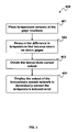
- FIG. 4 illustrates a high-level flow chart of operations depicting logical operational steps of a method for dynamic differential temperature compensation for strain gage based sensors, which can be implemented in accordance with an alternative embodiment.
- FIG. 1 illustrates a circuit diagram 100 for analog dynamic differential temperature compensation for a strain gage based sensor device 110 , which can be implemented in accordance with a preferred embodiment.
- Strain gage network 102 usually employs strain sensing elements ⁇ T 1 , ⁇ T 2 , ⁇ C 1 and ⁇ C 2 electrically connected to form a Wheatstone bridge type circuit.
- Input voltage 106 can be given to the strain gage network 102 and temperature gage network 104 .
- the total strain and/or the output of the gage network can be equivalent to the difference in strain between tension gages ( ⁇ T 1 and ⁇ T 2 ) and compression gages ( ⁇ C 1 and ⁇ C 2 ).
- the output can be given to temperature compensation network 104 , which can also be a Wheatstone bridge type circuit with temperature sensing elements T 1 , T 2 , T 3 and T 4 .
- the output measured between 103 and 105 of the temperature compensation network 104 , can be used to correct unwanted thermally induced error between 101 and 103 .
- the compensated output now becomes the voltage between 101 and 105 .
- the supply voltage for the circuit 100 would be provided across points 106 and 107 .
- FIG. 2 illustrates a sensing element experiencing a temperature gradient 200 , which can be implemented in accordance with a preferred embodiment.
- the temperature gradient can be in a direction along a strain gage sensing device 210 as indicated by arrow 201 .
- the temperature can be measured at strain sensing device locations 202 (T 1 and T 2 in FIG. 1) and 203 (C 1 and C 2 in FIG. 1 ) using temperature sensing devices.
- the difference in temperature of the temperature sensors 204 and 205 can be used as the input of a mathematical algorithm that can compensate the output for the strain gage bridge shown in FIG. 1 .
- FIG. 3 illustrates a graph 300 , depicting output error with respect to difference in temperature at strain gage locations, which can be corrected in accordance with the preferred embodiment.
- FIG. 3 illustrates that, if the output is looked at as a function of temperature differential, a relationship exists.
- the graph 300 indicates that the output error changes predictably with temperature differential. If the temperature changes dynamically, temperature gradients, similar to those illustrated, can be induced, thus creating the output error.
- FIG. 4 illustrates a high-level flow chart of operations depicting logical operational steps of a method 400 for dynamic differential temperature compensation for strain gage based sensors, which can be implemented in accordance with a preferred embodiment.
- temperature sensors can be placed at the strain gage locations.
- the difference in temperature that induces strain on the strain gages can be measured.
- the output of the temperature sensor network can be obtained.
- the temperature sensor output can be employed to dynamically correct temperature induced strain in the strain gage.
Landscapes
- Physics & Mathematics (AREA)
- General Physics & Mathematics (AREA)
- Measurement Of Force In General (AREA)
- Measurement Of Length, Angles, Or The Like Using Electric Or Magnetic Means (AREA)
Abstract
Description
Claims (17)
Priority Applications (1)
| Application Number | Priority Date | Filing Date | Title |
|---|---|---|---|
| US11/897,158 US7647837B2 (en) | 2007-08-29 | 2007-08-29 | Active temperature differential compensation for strain gage based sensors |
Applications Claiming Priority (1)
| Application Number | Priority Date | Filing Date | Title |
|---|---|---|---|
| US11/897,158 US7647837B2 (en) | 2007-08-29 | 2007-08-29 | Active temperature differential compensation for strain gage based sensors |
Publications (2)
| Publication Number | Publication Date |
|---|---|
| US20090056466A1 US20090056466A1 (en) | 2009-03-05 |
| US7647837B2 true US7647837B2 (en) | 2010-01-19 |
Family
ID=40405391
Family Applications (1)
| Application Number | Title | Priority Date | Filing Date |
|---|---|---|---|
| US11/897,158 Active 2027-09-04 US7647837B2 (en) | 2007-08-29 | 2007-08-29 | Active temperature differential compensation for strain gage based sensors |
Country Status (1)
| Country | Link |
|---|---|
| US (1) | US7647837B2 (en) |
Cited By (11)
| Publication number | Priority date | Publication date | Assignee | Title |
|---|---|---|---|---|
| US20110181424A1 (en) * | 2010-01-22 | 2011-07-28 | Tsinghua University | Temperature control switch, method for using the same and alarm system using the same |
| RU2469262C1 (en) * | 2011-05-23 | 2012-12-10 | Российская Федерация, от имени которой выступает Министерство промышленности и торговли Российской Федерации (Минпромторг России) | Correction method of measurement results of strain-gauge bridge transmitter with instrument amplifier |
| US9261419B2 (en) | 2014-01-23 | 2016-02-16 | Honeywell International Inc. | Modular load structure assembly having internal strain gaged sensing |
| EP3566937A1 (en) | 2018-05-11 | 2019-11-13 | Campagnolo S.r.l. | Bicycle component provided with a temperature-compensated stress/strain sensor |
| US11377169B2 (en) | 2018-05-11 | 2022-07-05 | Campagnolo S.R.L. | Bicycle crankarm and related crankset |
| US11401002B2 (en) | 2018-05-11 | 2022-08-02 | Campagnolo S.R.L. | Bicycle crankarm having a stress/strain detector for a torque meter or a power meter, and methods for manufacturing and using the crankarm |
| US11547004B2 (en) | 2018-05-11 | 2023-01-03 | Campagnolo S.R.L. | Bicycle component made of composite material and related manufacturing process |
| US11597469B2 (en) | 2018-05-11 | 2023-03-07 | Campagnolo S.R.L. | Bicycle crankarm provided with electric/electronic system |
| US20230127473A1 (en) * | 2020-03-19 | 2023-04-27 | Shenzhen New Degree Technology Co., Ltd. | Strain sensing film, pressure sensor and hybrid strain sensing system |
| US11714015B1 (en) | 2022-03-29 | 2023-08-01 | Rosemount Aerospace Inc. | Method for thermoelectric effect error correction |
| US12535371B2 (en) * | 2020-09-18 | 2026-01-27 | Shenzhen New Degree Technology Co., Ltd. | Temperature and pressure sensors with different temperature coefficients of resistance and electronic device |
Families Citing this family (7)
| Publication number | Priority date | Publication date | Assignee | Title |
|---|---|---|---|---|
| WO2011128047A1 (en) * | 2010-04-12 | 2011-10-20 | Aktiebolaget Skf | Load on object derived from natural-mode series modelling |
| MX365853B (en) | 2013-12-31 | 2019-06-17 | Halliburton Energy Services Inc | Method for multiplexing wheatstone bridge measurements. |
| US10167003B1 (en) * | 2015-05-15 | 2019-01-01 | Voestalpine Signaling Usa Inc. | Automated rail inspection system |
| CN110546474B (en) | 2017-04-25 | 2022-01-21 | 奥腾工业自动化(廊坊)有限公司 | Method for temperature compensation of force/torque sensor |
| CN109029236A (en) * | 2018-07-25 | 2018-12-18 | 中铁第四勘察设计院集团有限公司 | It is a kind of to eliminate the engineering structure mechanical strain test method and device that temperature influences |
| EP3771895B1 (en) * | 2019-07-31 | 2023-11-01 | ABB Schweiz AG | Temperature compensated strain gauge measurements |
| CN119714657B (en) * | 2025-02-27 | 2025-05-16 | 锐马(福建)电气制造有限公司 | A method for measuring and compensating temperature drift of a six-dimensional force sensor |
Citations (10)
| Publication number | Priority date | Publication date | Assignee | Title |
|---|---|---|---|---|
| US3665756A (en) * | 1965-10-18 | 1972-05-30 | Microdot Inc | Strain gauge temperature compensation system |
| US4023864A (en) | 1973-09-20 | 1977-05-17 | Lang Davis Industries, Inc. | Automatic stability control system with strain gauge sensors |
| US4448078A (en) * | 1982-11-23 | 1984-05-15 | The United States Of America As Represented By The Secretary Of The Air Force | Three-wire static strain gage apparatus |
| US4785673A (en) | 1985-12-17 | 1988-11-22 | S.C.A.I.M.E. | Strain-gauge sensor for measuring forces |
| US6001666A (en) | 1996-03-28 | 1999-12-14 | Commissariat A L'energie Atomique | Manufacturing process of strain gauge sensor using the piezoresistive effect |
| US6173619B1 (en) * | 1996-12-05 | 2001-01-16 | Satake Corporation | Method and device for effecting temperature compensation in load cell type load detector |
| US6862937B2 (en) * | 2002-01-18 | 2005-03-08 | Toyoda Koki Kabushiki Kaisha | Load sensor, temperature compensation method for the load sensor and manufacturing method of the load sensor |
| US6973837B2 (en) * | 2001-07-13 | 2005-12-13 | Barnett John D | Temperature compensated strain sensing apparatus |
| US7146862B2 (en) | 2004-06-02 | 2006-12-12 | Honeywell International Inc. | Thick film strain gage sensor |
| US7334483B2 (en) * | 2006-01-27 | 2008-02-26 | Schlumberger Technology Corporation | Thermal compensation of pressure measurements |
-
2007
- 2007-08-29 US US11/897,158 patent/US7647837B2/en active Active
Patent Citations (10)
| Publication number | Priority date | Publication date | Assignee | Title |
|---|---|---|---|---|
| US3665756A (en) * | 1965-10-18 | 1972-05-30 | Microdot Inc | Strain gauge temperature compensation system |
| US4023864A (en) | 1973-09-20 | 1977-05-17 | Lang Davis Industries, Inc. | Automatic stability control system with strain gauge sensors |
| US4448078A (en) * | 1982-11-23 | 1984-05-15 | The United States Of America As Represented By The Secretary Of The Air Force | Three-wire static strain gage apparatus |
| US4785673A (en) | 1985-12-17 | 1988-11-22 | S.C.A.I.M.E. | Strain-gauge sensor for measuring forces |
| US6001666A (en) | 1996-03-28 | 1999-12-14 | Commissariat A L'energie Atomique | Manufacturing process of strain gauge sensor using the piezoresistive effect |
| US6173619B1 (en) * | 1996-12-05 | 2001-01-16 | Satake Corporation | Method and device for effecting temperature compensation in load cell type load detector |
| US6973837B2 (en) * | 2001-07-13 | 2005-12-13 | Barnett John D | Temperature compensated strain sensing apparatus |
| US6862937B2 (en) * | 2002-01-18 | 2005-03-08 | Toyoda Koki Kabushiki Kaisha | Load sensor, temperature compensation method for the load sensor and manufacturing method of the load sensor |
| US7146862B2 (en) | 2004-06-02 | 2006-12-12 | Honeywell International Inc. | Thick film strain gage sensor |
| US7334483B2 (en) * | 2006-01-27 | 2008-02-26 | Schlumberger Technology Corporation | Thermal compensation of pressure measurements |
Cited By (14)
| Publication number | Priority date | Publication date | Assignee | Title |
|---|---|---|---|---|
| US20110181424A1 (en) * | 2010-01-22 | 2011-07-28 | Tsinghua University | Temperature control switch, method for using the same and alarm system using the same |
| US8514088B2 (en) * | 2010-01-22 | 2013-08-20 | Tsinghua University | Temperature control switch, method for using the same and alarm system using the same |
| RU2469262C1 (en) * | 2011-05-23 | 2012-12-10 | Российская Федерация, от имени которой выступает Министерство промышленности и торговли Российской Федерации (Минпромторг России) | Correction method of measurement results of strain-gauge bridge transmitter with instrument amplifier |
| US9261419B2 (en) | 2014-01-23 | 2016-02-16 | Honeywell International Inc. | Modular load structure assembly having internal strain gaged sensing |
| US11377169B2 (en) | 2018-05-11 | 2022-07-05 | Campagnolo S.R.L. | Bicycle crankarm and related crankset |
| US11214331B2 (en) | 2018-05-11 | 2022-01-04 | Campagnolo S.R.L. | Bicycle component provided with a temperature-compensated stress/strain sensor |
| EP3566937A1 (en) | 2018-05-11 | 2019-11-13 | Campagnolo S.r.l. | Bicycle component provided with a temperature-compensated stress/strain sensor |
| US11401002B2 (en) | 2018-05-11 | 2022-08-02 | Campagnolo S.R.L. | Bicycle crankarm having a stress/strain detector for a torque meter or a power meter, and methods for manufacturing and using the crankarm |
| US11547004B2 (en) | 2018-05-11 | 2023-01-03 | Campagnolo S.R.L. | Bicycle component made of composite material and related manufacturing process |
| US11577801B2 (en) | 2018-05-11 | 2023-02-14 | Campagnolo S.R.L. | Bicycle component provided with a temperature-compensated stress/strain sensor |
| US11597469B2 (en) | 2018-05-11 | 2023-03-07 | Campagnolo S.R.L. | Bicycle crankarm provided with electric/electronic system |
| US20230127473A1 (en) * | 2020-03-19 | 2023-04-27 | Shenzhen New Degree Technology Co., Ltd. | Strain sensing film, pressure sensor and hybrid strain sensing system |
| US12535371B2 (en) * | 2020-09-18 | 2026-01-27 | Shenzhen New Degree Technology Co., Ltd. | Temperature and pressure sensors with different temperature coefficients of resistance and electronic device |
| US11714015B1 (en) | 2022-03-29 | 2023-08-01 | Rosemount Aerospace Inc. | Method for thermoelectric effect error correction |
Also Published As
| Publication number | Publication date |
|---|---|
| US20090056466A1 (en) | 2009-03-05 |
Similar Documents
| Publication | Publication Date | Title |
|---|---|---|
| US7647837B2 (en) | Active temperature differential compensation for strain gage based sensors | |
| JP6714083B2 (en) | Sensor element for pressure sensor | |
| US8984951B2 (en) | Self-heated pressure sensor assemblies | |
| US8874387B2 (en) | Air flow measurement device and air flow correction method | |
| US11287347B2 (en) | Temperature-compensated strain gauge measurements | |
| US6732570B2 (en) | Method and apparatus for measuring a fluid characteristic | |
| WO2018037721A1 (en) | Thermal humidity measuring device | |
| JP7168340B2 (en) | thermal flow meter | |
| WO2010090972A2 (en) | Method for temperature compensation of a piezoresistive gaged metal diaphragm | |
| US8893554B2 (en) | System and method for passively compensating pressure sensors | |
| US7613586B2 (en) | Thermal vacuum gauge | |
| Gdoutos | Electrical resistance strain gages | |
| US12480825B2 (en) | Thermometer having a diagnostic function | |
| JP7436218B2 (en) | pressure sensor | |
| Hufnagel | Strain Measurement | |
| JP2019066253A (en) | Flow rate measuring device | |
| Kleckers | Fibre Bragg sensors compared with electrical strain gauges for use in force measurement-Prospects and potentials | |
| US7426862B2 (en) | Thermal accelerometer with automatic zero control | |
| Katz | Factors affecting strain gauge selection for smart structure applications | |
| JP4657805B2 (en) | Temperature characteristics adjustment method for thermal flow sensor | |
| Kuttner et al. | Deformation Transducers | |
| Karimov | Digital enhancement of analog measurement systems for temperature compensation of strain gages | |
| JP2004093321A (en) | Bridge circuit type detector | |
| CN119343585A (en) | Strain gauge sensor | |
| WO2025158824A1 (en) | Flow sensor and program |
Legal Events
| Date | Code | Title | Description |
|---|---|---|---|
| AS | Assignment |
Owner name: HONEYWELL INTERNATIONAL INC., NEW JERSEY Free format text: ASSIGNMENT OF ASSIGNORS INTEREST;ASSIGNORS:MORAN, MICHAEL E.;GREGORY, SEAN D.;ROBINSON, JASON R.;AND OTHERS;REEL/FRAME:019824/0398;SIGNING DATES FROM 20070820 TO 20070822 |
|
| STCF | Information on status: patent grant |
Free format text: PATENTED CASE |
|
| FPAY | Fee payment |
Year of fee payment: 4 |
|
| FPAY | Fee payment |
Year of fee payment: 8 |
|
| MAFP | Maintenance fee payment |
Free format text: PAYMENT OF MAINTENANCE FEE, 12TH YEAR, LARGE ENTITY (ORIGINAL EVENT CODE: M1553); ENTITY STATUS OF PATENT OWNER: LARGE ENTITY Year of fee payment: 12 |