US7630787B2 - System for integrating insert with molded article - Google Patents
System for integrating insert with molded article Download PDFInfo
- Publication number
- US7630787B2 US7630787B2 US11/406,424 US40642406A US7630787B2 US 7630787 B2 US7630787 B2 US 7630787B2 US 40642406 A US40642406 A US 40642406A US 7630787 B2 US7630787 B2 US 7630787B2
- Authority
- US
- United States
- Prior art keywords
- insert
- mold
- station
- molded article
- moving assembly
- Prior art date
- Legal status (The legal status is an assumption and is not a legal conclusion. Google has not performed a legal analysis and makes no representation as to the accuracy of the status listed.)
- Expired - Fee Related, expires
Links
Images


Classifications
-
- B—PERFORMING OPERATIONS; TRANSPORTING
- B29—WORKING OF PLASTICS; WORKING OF SUBSTANCES IN A PLASTIC STATE IN GENERAL
- B29C—SHAPING OR JOINING OF PLASTICS; SHAPING OF MATERIAL IN A PLASTIC STATE, NOT OTHERWISE PROVIDED FOR; AFTER-TREATMENT OF THE SHAPED PRODUCTS, e.g. REPAIRING
- B29C45/00—Injection moulding, i.e. forcing the required volume of moulding material through a nozzle into a closed mould; Apparatus therefor
- B29C45/0053—Injection moulding, i.e. forcing the required volume of moulding material through a nozzle into a closed mould; Apparatus therefor combined with a final operation, e.g. shaping
-
- B—PERFORMING OPERATIONS; TRANSPORTING
- B21—MECHANICAL METAL-WORKING WITHOUT ESSENTIALLY REMOVING MATERIAL; PUNCHING METAL
- B21D—WORKING OR PROCESSING OF SHEET METAL OR METAL TUBES, RODS OR PROFILES WITHOUT ESSENTIALLY REMOVING MATERIAL; PUNCHING METAL
- B21D26/00—Shaping without cutting otherwise than using rigid devices or tools or yieldable or resilient pads, i.e. applying fluid pressure or magnetic forces
- B21D26/02—Shaping without cutting otherwise than using rigid devices or tools or yieldable or resilient pads, i.e. applying fluid pressure or magnetic forces by applying fluid pressure
- B21D26/021—Deforming sheet bodies
- B21D26/023—Deforming sheet bodies including an additional treatment performed by fluid pressure, e.g. perforating
-
- B—PERFORMING OPERATIONS; TRANSPORTING
- B29—WORKING OF PLASTICS; WORKING OF SUBSTANCES IN A PLASTIC STATE IN GENERAL
- B29C—SHAPING OR JOINING OF PLASTICS; SHAPING OF MATERIAL IN A PLASTIC STATE, NOT OTHERWISE PROVIDED FOR; AFTER-TREATMENT OF THE SHAPED PRODUCTS, e.g. REPAIRING
- B29C45/00—Injection moulding, i.e. forcing the required volume of moulding material through a nozzle into a closed mould; Apparatus therefor
- B29C45/03—Injection moulding apparatus
- B29C45/04—Injection moulding apparatus using movable moulds or mould halves
- B29C45/0441—Injection moulding apparatus using movable moulds or mould halves involving a rotational movement
- B29C45/045—Injection moulding apparatus using movable moulds or mould halves involving a rotational movement mounted on the circumference of a rotating support having a rotating axis perpendicular to the mould opening, closing or clamping direction
Definitions
- the present invention generally relates to, but is not limited to, systems, and more specifically the present invention relates to, but is not limited to, a system for integrating an insert with a molded article.
- WO Patent 2004/011315 (Inventor: Staargaard et al; Published: 2004 Feb. 5; Assignee: General Electric Company, USA), WO Patent 2004/056610 (Inventor: Staargaard; Published: 2004 Jul. 8; Assignee: General Electric Company, USA) and US Patent Application 2003/0077409 (Inventor: Schnell; Published: 2003 Apr. 24) all appear to disclose a process and system for inserting a hydro-formed metal insert into a mold of a molding machine, and then partially encapsulating or overmolding the formed insert with a molding material (such as a plastic resin).
- a molding material such as a plastic resin
- EP Patent 826,476 (Inventor: Buchholz; Published: 1998 Mar. 4; Assignee: Tecumseh Products Company, USA) appears to disclose loading and forming an insert (that is, a tube) in a single mold of a molding system, and then encapsulating or overmolding the insert with a molding material (such as a plastic resin).
- This approach includes performing the forming operation and the overmolding operation in the single mold.
- An article titled Secondary Operations: Unique System Uses Press Motion As Punch and Die discloses a molding system having a mold. With the mold opened, a press operator loads a metal insert (that is a metal buss bar) into the mold. As a press closes and clamps, a punch and die mechanism pierces a slug in the insert, and then a nylon-based molding material is injected into the mold to overmold the insert. The forming operation and the overmolding operation are performed sequentially in the same mold.
- a metal insert that is a metal buss bar
- a document (dated October 1989, titled ALPHA—Multi - processing Technology and published by Krauss Maffei of Germany), discloses the ALPHA molding system that appears to be an integration of several types of molding systems (such as, for example, a compression molding system, an injection molding system and/or a gas-pressure molding system). This arrangement appears to combine different molding materials into a molded article using different processes.
- a system comprising: a mold-moving assembly being cooperative with a molding station and an insert-integration station, the molding station and the mold-moving assembly being cooperative to mold a molded article, the mold-moving assembly being configured to move the molded article from the molding station over to the insert-integration station, the insert-integration station being configured to integrate an insert to the molded article to manufacture a composite article, the composite article being the insert integrated with the molded article, and the insert-integration station being cooperative with the mold-moving assembly to form, at least in part, the insert of the composite article, and once the insert has been formed, the composite article is ejected from the insert-integration station.
- a system comprising: a mold half of a set of mold halves configured to cooperate with a mold-moving assembly, the mold-moving assembly being cooperative with a molding station and an insert-integration station, the molding station and the mold-moving assembly being cooperative to mold a molded article, the mold-moving assembly being configured to move the molded article from the molding station over to the insert-integration station, the insert-integration station being configured to integrate an insert to the molded article to manufacture a composite article, the composite article being the insert integrated with the molded article, and the insert-integration station being cooperative with the mold-moving assembly to form, at least in part, the insert of the composite article, and once the insert has been formed, the composite article is ejected from the insert-integration station.
- a system comprising: an insert-integration station configured to cooperate with a mold-moving assembly, the mold-moving assembly being cooperative with a molding station and the insert-integration station, the molding station and the mold-moving assembly being cooperative to mold a molded article, the mold-moving assembly being configured to move the molded article from the molding station over to the insert-integration station, the insert-integration station being configured to integrate an insert to the molded article to manufacture a composite article, the composite article being the insert integrated with the molded article, and the insert-integration station being cooperative with the mold-moving assembly to form, at least in part, the insert of the composite article, and once the insert has been formed, the composite article is ejected from the insert-integration station.
- a system comprising: a mold half of a group of mold halves configured to cooperate with an insert-integration station, the insert-integration station configured to cooperate with a mold-moving assembly, the mold-moving assembly being cooperative with a molding station and the insert-integration station, the molding station and the mold-moving assembly being cooperative to mold a molded article, the mold-moving assembly being configured to move the molded article from the molding station over to the insert-integration station, the insert-integration station being configured to integrate an insert to the molded article to manufacture a composite article, the composite article being the insert integrated with the molded article, and the insert-integration station being cooperative with the mold-moving assembly to form, at least in part, the insert of the composite article, and once the insert has been formed, the composite article is ejected from the insert-integration station.
- a system comprising: a molding station configured to cooperate with a mold-moving assembly, the mold-moving assembly being cooperative with the molding station and an insert-integration station, the molding station and the mold-moving assembly being cooperative to mold a molded article, the mold-moving assembly being configured to move the molded article from the molding station over to the insert-integration station, the insert-integration station being configured to integrate an insert to the molded article to manufacture a composite article, the composite article being the insert integrated with the molded article, and the insert-integration station being cooperative with the mold-moving assembly to form, at least in part, the insert of the composite article, and once the insert has been formed, the composite article is ejected from the insert-integration station.
- a system comprising: a mold half of a collection of mold halves configured to cooperate with a molding station, the molding station configured to cooperate with a mold-moving assembly, the mold-moving assembly being cooperative with an insert-integration station, the molding station and the mold-moving assembly being cooperative to mold a molded article, the mold-moving assembly being configured to move the molded article from the molding station over to the insert-integration station, the insert-integration station being configured to integrate an insert to the molded article to manufacture a composite article, the composite article being the insert integrated with the molded article, and the insert-integration station being cooperative with the mold-moving assembly to form, at least in part, the insert of the composite article, and once the insert has been formed, the composite article is ejected from the insert-integration station.
- a method comprising: configuring a mold-moving assembly to: cooperate with a molding station and an insert-integration station, the molding station and the mold-moving assembly being cooperative to mold a molded article, the mold-moving assembly being configured to move the molded article from the molding station over to the insert-integration station, the insert-integration station being configured to integrate an insert to the molded article to manufacture a composite article, the composite article being the insert integrated with the molded article, and the insert-integration station being cooperative with the mold-moving assembly to form, at least in part, the insert of the composite article, and once the insert has been formed, the composite article is ejected from the insert-integration station.
- an article of manufacture for directing a data processing system to control a molding system operatively connectable to the data processing system
- the article of manufacture comprising: a data processing system usable medium embodying one or more instructions executable by the data processing system, the data processing system usable medium being a memory device having the one or more instructions and the one or more instructions including: instructions for directing the data processing system to direct a mold-moving assembly to: cooperate with a molding station and an insert-integration station, the molding station and the mold-moving assembly being cooperative to mold a molded article, the mold-moving assembly being configured to move the molded article from the molding station over to the insert-integration station, the insert-integration station being configured to integrate an insert to the molded article to manufacture a composite article, the composite article being the insert integrated with the molded article, and the insert-integration station being cooperative with the mold-moving assembly to form, at least in part, the insert of the composite article, and once the insert has been formed, the composite
- a technical effect is reduction in complexity in a system for molding articles having an insert.
- FIGS. 1A to 1D are side-elevation views of a system according to a first exemplary embodiment
- FIG. 2A is a side view of mold halves that are placed in a position to mold a molded article in a molding station of the system of FIG. 1A ;
- FIGS. 2B , 2 C and 2 D are side elevation views of a mold half that is rotated and placed in an insert-integration station of the system of FIG. 1A ;
- FIG. 2E is a side view of mold halves that are placed in a position to form an insert in an insert-integration station of the system of FIG. 1A ;
- FIG. 2F is a side elevation view of an composite article manufactured by the system of FIG. 1A ;
- FIG. 3 is a block schematic diagram of an article of manufacture according to a second exemplary embodiment, the article for directing a data processing system to control the system of FIG. 1A .
- FIGS. 1A to 1D are side-elevation views of a system 100 according to the first exemplary embodiment.
- the elements or components of the system 100 may be supplied by different vendors in different combinations and permutations or may be supplied by a single vendor.
- FIG. 1A depicts a first phase of a cycle of the system 100 .
- the system 100 uses a mold-moving assembly 102 that cooperates with a molding station 110 and an insert-integration station 112 .
- the molding station 110 and the assembly 102 cooperate to mold a molded article.
- the mold-moving assembly 102 moves the molded article from the molding station 110 over to the insert-integration station 112 .
- an insert is integrated to the molded article to manufacture a composite article.
- the insert-integration station 112 in cooperation with the mold-moving assembly 102 forms the insert of the composite article into a predetermined shape or condition. Once the insert has been formed, the composite article is ejected from the insert-integration station 112 .
- a technical effect is reduction in complexity in a system for molding articles having an insert.
- the insert-integration station 112 may include insert-forming operations, such as stamping, punching, bending and/or hydroforming, etc.
- Examples of the types of composite articles than may be manufactured by the system 100 are: cooling fans used in a vehicle radiator, a vehicle bumper assembly, a vehicle-running board, etc, or non-vehicle applications.
- the operation of the molding station 110 and of the insert-integration station 112 overlap one another at least in part so that a reduction in cycle time is achieved.
- operation of the molding station 110 and of the insert-integration station 112 occur simultaneously or near simultaneously (that is, overlap of the operations occur concurrently) for best possible reduction in cycle time.
- Attached to the mold-moving assembly 102 is a set of mold halves ( 106 , 108 ).
- the set of mold halves ( 106 , 108 ) includes the mold half 106 and the mold half 108 .
- Actuators 111 are used to stroke or slide the mold-moving assembly 102 along a base 104 toward and away from the molding station 110 . Another pair of actuators similar to the actuators 111 is used but they are hidden in this view of the system 100 .
- the mold-moving assembly 102 includes an actuator (not depicted) that is used to rotate the mold halves 106 , 108 one hundred and eighty degrees between the stations 110 , 112 .
- the molding station 110 uses a group of mold halves ( 106 , 108 , 114 ) to mold articles by alternately using the combination of mold halves ( 106 , 114 ) or the combination of mold halves ( 108 , 114 ).
- the group of mold halves ( 106 , 108 , 114 ) shares at least one mold half that is common with the set of mold halves ( 106 , 108 ).
- the mold half 114 is attached to a stationary platen 116 .
- An injection unit 118 is used to prepare and deliver a molding material to the molding station 110 .
- the molding material may be a plastic-based resin, a plastic-based resin in combination with a reinforcement (such as fibers), a metallic alloy (such as magnesium) or a metallic alloy in combination with a reinforcement (such as a ceramic powder).
- the actuators 111 are actuated to stroke the mold-moving assembly 102 toward the stationary platen 116 so that the mold halves 106 , 114 are closed against each other. Then the mold halves 106 , 114 are clamped up. The process for clamping up mold halves is explained below. Then the injection unit 118 delivers the molding material into a mold cavity defined by the mold halves 106 , 114 (that are closed and clamped against each other) to mold a molded article 120 . The article 120 is retained by the mold half 106 once the mold halves 106 , 114 are made to break apart from each other. The process for breaking apart the mold halves will be explained below.
- the actuators 111 stroke the mold moving assembly 102 away from the stationary platen 116 so that the mold halves 106 , 114 become spaced apart from each other.
- the mold-moving assembly 102 will then be actuated to rotate the mold half 106 away from the molding station 110 and over to the insert-integration station 112 , and will then be actuated to rotate the mold half 108 away from the insert-integration station 112 and over to the molding station 110 .
- An insert-delivery assembly 126 will be actuated to deliver an insert to the insert-integration station 112 , and then be actuated to position the insert proximate to the molded article that is releasably retained by the mold half 108 .
- the mold half 108 will then be actuated to retain the insert proximate to the molded article.
- the insert includes flanges that engage the molded article retained by the mold half 108 .
- the flanges are not depicted in FIG. 1A but they are depicted in FIG. 2C . It will be appreciated that other types of features on the insert may be used in place of the flange, such as a rib extending from the insert, a groove formed by the insert, etc.
- the insert-integration station 112 uses a collection of mold halves ( 106 , 108 , 122 ) to form the insert of the composite article 128 that is retained by the mold half 108 .
- the station 112 alternately uses the combination of mold halves ( 106 , 122 ) and the combination of mold halves ( 108 , 122 ) to form the insert of the composite article 128 .
- the collection of mold halves ( 106 , 108 , 122 ) shares are least one mold half that is common with the set of mold halves ( 106 , 108 ).
- a mold half 122 is attached to a movable platen 124 .
- An actuator 109 is used to stroke or to linearly translate the movable platen 124 along the base 104 toward and away from the mold-moving assembly 102 so that the mold halves 108 , 122 may be opened and closed. Another actuator similar to the actuator 109 is also used but it is hidden in this view of the system 100 .
- Tie bars 103 extend from the stationary platen 116 , through the movable platen 124 and over to a tie-bar support assembly 105 . Another pair of tie bars is used but they are hidden behind the tie bars 103 in this view.
- the tie-bar support assembly 105 is used to prevent the tie bars 103 from sagging.
- the tie-bar-support assembly 105 is optional, and that the tie bars 103 may extend and sag a little and not require support.
- the actuator 109 strokes the movable platen 124 toward the mold-moving assembly 102 , the mold halves 108 , 122 become closed against one another.
- a clamping mechanism 138 is actuated to apply a clamping force via the tie bars 103 to clamp the mold halves 108 , 122 together.
- the insert (that is integrated to the molded article) may be formed.
- the insert includes a metallic component and the process for forming the insert is a hydro-forming process.
- the process of closing and/or clamping the mold halves 108 , 122 relative to each other causes the insert to be formed.
- forming of the insert may occur in several ways: (i) the mold halves are closed and then the insert is formed; (ii) the insert is formed while the mold halves are being made to close against each other; (iii) the insert is formed prior to the mold halves being made to close; (iv) the mold halves are used in the process of forming the insert; and/or (v) the mold halves are not used in the process of forming the insert.
- the clamping mechanism 138 is located in the movable platen 124 .
- the clamping mechanism 138 is used to apply a clamping force to the tie bars 103 so that the mold halves 106 , 114 , and the mold halves 108 , 122 may be clamped up once they are closed together relative to each other.
- the clamping mechanism 138 is also used to apply a mold-break force to break apart mold halves that were formerly clamped together.
- the clamping mechanism 138 includes, for example, a pineapple-type clamping mechanism as known in the art. Other types of clamps (non-pineapple type) may be used in the system 100 .
- the actuators 111 are actuated to move the mold-moving assembly 102 toward the stationary platen 116 so that the mold halves 106 , 114 are closed together, and the actuator 109 is actuated to move the platen 124 toward the mold-moving assembly 102 so that the mold halves 108 , 122 are closed together.
- the clamping mechanism 138 applies a clamping force to the tie bars 103 which act to clamp up the mold halves.
- the mold halves 106 , 114 are used to mold the molded article 120 (as previously described), and the mold halves 108 , 122 are used to form or to shape the insert attached to a molded article to manufacture the composite article 128 .
- the clamping mechanism 138 is actuated to remove the clamping force and is then actuated to apply a mold break force that breaks mold halves apart from each other.
- the actuator 109 is actuated to move the platen 124 away from the mold-moving assembly 102
- the actuators 111 are actuated to move the mold-moving assembly 102 away from the platen 116 .
- the mold halves 106 , 114 are separated from each other (while the mold half 106 releasably retains the molded article 120 ), and the mold halves 108 , 122 are separated from each other (while the mold half 108 releasably retains the article 128 ).
- the composite article 128 is ejected (or released) from the mold half 108 .
- the mold-moving assembly 102 is actuated to rotate the mold halves 106 , 108 one hundred and eighty degrees so that the mold half 108 then faces the mold half 114 and the mold half 106 then faces the mold half 122 , and in effect the molded article 120 is moved from the station 110 over to the station 112 .
- FIG. 1B depicts a second phase of the cycle of the system 100 .
- the actuator 109 actuates to translate the movable platen 124 away from the mold-moving assembly 102 so that the mold half 122 becomes spaced apart from the mold half 108 and the mold half 108 actuatably releases the composite article 128 from the insert-integration station 112 .
- the insert-delivery assembly 126 is ready to supply another insert 130 to the insert-integration station 112 .
- the actuator 111 is actuated to translate the mold-moving assembly 102 away from the mold half 114 so that the mold half 106 may then become spaced apart from the mold half 114 .
- the mold half 106 releasably retains the molded article 120 .
- FIG. 1C depicts a third phase of the cycle of the system 100 .
- the mold-moving assembly 102 is actuated to rotate the mold half 106 from the molding station 110 over to the insert-integration station 112 so that the mold half 106 may become positioned to cooperate with the mold half 122 .
- the mold-moving assembly 102 also rotates the mold half 108 from the insert-integration station 112 over to the molding station 1 10 so that the mold half 108 may become positioned to cooperate with the mold half 114 .
- FIG. 1D depicts a fourth phase of the cycle of the system 100 .
- the mold half 108 is now positioned to face the mold half 114 in the molding station 110 .
- a new molded article is molded once the mold halves 108 , 114 are actuated to become closed and clamped against each other.
- the mold half 106 which is shown retaining the molded article 120 , is now positioned to face the mold half 122 in the insert-integration station 112 so that the insert 130 may become integrated with the molded article 120 .
- the insert-delivery assembly 126 places the insert 130 within the insert-integration station 112 and then engages the insert 130 to the molded article 120 .
- a new composite article is manufactured once the mold halves 106 , 122 are actuated to become closed and clamped against each other so that the insert 130 (that is integrated to the article 120 ) may be formed. Integration of an insert with a molded article is explained below with reference to FIGS. 2A to 2F .
- FIG. 2A is a side view of the mold halves 106 , 114 that are closed against each other and clamped up so that the mold halves define the molding cavity.
- the molding material is injected into the mold cavity to mold the molded article 120 in the molding station 110 of the system 100 .
- the description of the mold half 106 is equally applicable to the mold half 108 .
- the molded article 120 is molded to have a passageway that passes through the molded article 120 .
- An insert (depicted in FIGS. 2C and 2D ) will be made to enter the passageway of the molded article 120 at least in part and engage with the molded article 120 .
- the insert attaches to a peripheral edge along the passageway of the molded article 120 .
- the mold half 106 includes mold inserts 132 that are actuatably slidable within the mold half 106 .
- the mold inserts 132 will be actuated forwardly to form the cavity that will be used to mold or shape the molded article 120 .
- the mold halves 106 and 114 will be separated from each other. Once the mold half 106 is moved into the insert-integration station 112 , the mold inserts 132 will be translated away from the molded article 120 so that the insert 130 may be integrated with the molded article 120 .
- the mold half 106 includes a hydro-forming fluid line 134 that will be used to transport a hydro-forming fluid into the hollow body of insert 130 so that the hydro-forming fluid may be used to hydro-form the insert (the insert includes a hollow body for example).
- the flange of the insert may be made during a forming process initiated in the station 112 .
- FIGS. 2B , 2 C and 2 D are side elevation views of the mold half 106 that is rotated and placed in the insert-integration station 112 of the system 100 of FIG. 1A .
- FIG. 2B depicts the mold half 106 as a core half.
- the mold half 106 releasably retains the mold article 120 (by mechanisms not depicted).
- the mold inserts 132 have been retracted to expose protruding flanges of the molded article 120 .
- Other features are contemplated, such as lip, recess, clip, fastener, etc.
- FIG. 2C depicts the insert 130 delivered by the insert-delivery assembly 126 (not depicted in FIG. 2C ) to a position that is proximate to the article 120 retained by the mold half 106 .
- the insert 130 includes a hollow metallic body.
- the insert 130 includes flanges 136 that are used to engage the flanges of the molded article 120 .
- the insert 130 includes an orifice that is to be connected to the hydro-forming fluid line 134 .
- FIG. 2D depicts the flanges of the insert 130 positioned proximate to the flange of the molded article 120 .
- the mold half 106 includes a gripping mechanism (not depicted) for gripping and retaining the insert 130 proximate to the article 120 .
- the insert-delivery assembly 126 (not depicted in FIG. 2D ) positioned the insert 130 proximate to the molded article 120 , and then the gripping mechanism of the mold half 106 was actuated to retain the insert 130 proximate to the article 120 .
- a vacuum line (not depicted) may be used to releasably retain the insert 130 and/or the article 120 against the mold half 106 .
- an electromagnet (not depicted) may be used to retain and hold the insert 130 against the mold half 106 .
- a mechanical gripper (not depicted) may be used to grab and to releasably retain the insert 130 and/or the article 120 against the mold half 106 .
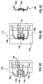
- FIG. 2E is a side view of the mold halves 106 , 122 that are placed in a position to form the insert 130 in the insert-integration station 112 .
- the mold halves 106 , 122 are closed and clamped against each other.
- a pressurized hydro-forming fluid is introduced into an interior cavity of the insert 130 (via the fluid line 134 that now fluidly communicates with the interior of the insert 130 ), and in response the insert 130 becomes deformed to conform to the mold surfaces that surround the insert 130 .
- the insert 130 is deformed sufficiently to engage the flanges of the molded article 120 and to conform to at least some of the mold surfaces while the insert 130 remains spaced apart from other mold surfaces at least in part.
- the degree of control exercised depends on the desired shape of the composite article 128 .
- a cross sectional strength of the plastic portion in the flange area may not be strong enough to resist forces applied by deformation of a metallic insert and the flange may collapse, whereas in other configurations the flange may be strong enough to resist modest deformation forces sufficiently enough to be able to form a mechanical engagement with the flanges on the insert 130 as the insert 130 deforms during the hydro-forming process.
- FIG. 2F is a side elevation view of the composite article 128 manufactured by the system 100 .
- the composite article includes the molded article 120 and the formed insert 130 .
- the mold-moving assembly 102 translates mold halves 106 , 108 along a vertically-aligned axis. According to another variant, the mold-moving assembly 102 translates the mold halves 106 , 108 along a horizontally-aligned axis.
- the mold half 106 is a core-type mold. According to another variant, the mold half 106 is a cavity-type mold. According to a variant, the mold half 108 is a core-type mold. According to another variant, the mold half 108 is a cavity-type mold.
- FIG. 3 is a block schematic diagram of an article of manufacture 300 for directing a data processing system 302 to control the system 100 of FIG. 1A .
- the system 100 is operatively connectable to the data processing system 302 .
- the article of manufacture 300 includes a data processing system usable medium 304 embodying one or more instructions 306 executable by the data processing system 302 .
- the one or more instructions 306 includes instructions for directing the data processing system to direct a mold-moving assembly 102 to move a molded article 120 between a molding station 110 and an insert-integration station 112 .
- the article of manufacture 300 may be a magnetic disk, an optical disk, a hard drive or RAM (Random Access Memory).
- the article of manufacture 300 may also be a signal that carries the one or more instructions over a network, such as the Internet, to the data processing system 302 .
- the one or more instructions 306 also includes, but is not limited to, the following in no particular order:
- the insert-integration station 112 including a group of mold halves 106 , 108 , 114 configured to cooperate with the set of mold halves 106 , 108 ;
- the molding station 110 configured to include a collection of mold halves 106 , 108 , 122 that are configured to cooperate with the set of mold halves 106 , 108 ;
Landscapes
- Engineering & Computer Science (AREA)
- Mechanical Engineering (AREA)
- Physics & Mathematics (AREA)
- Fluid Mechanics (AREA)
- Manufacturing & Machinery (AREA)
- Injection Moulding Of Plastics Or The Like (AREA)
- Moulds For Moulding Plastics Or The Like (AREA)
- Adornments (AREA)
- Sheet Holders (AREA)
- Air Bags (AREA)
Abstract
Description
Claims (18)
Priority Applications (8)
| Application Number | Priority Date | Filing Date | Title |
|---|---|---|---|
| US11/406,424 US7630787B2 (en) | 2006-04-19 | 2006-04-19 | System for integrating insert with molded article |
| CN2007800137233A CN101421088B (en) | 2006-04-19 | 2007-02-14 | System for integrating insert with molded article |
| EP07710619A EP2019744B1 (en) | 2006-04-19 | 2007-02-14 | System for integrating insert with molded article |
| DE602007007471T DE602007007471D1 (en) | 2006-04-19 | 2007-02-14 | SYSTEM FOR INTEGRATING AN INSERT WITH A FORM BODY |
| CA2644011A CA2644011C (en) | 2006-04-19 | 2007-02-14 | System for integrating insert with molded article |
| PCT/CA2007/000205 WO2007118302A1 (en) | 2006-04-19 | 2007-02-14 | System for integrating insert with molded article |
| AT07710619T ATE472400T1 (en) | 2006-04-19 | 2007-02-14 | SYSTEM FOR INTEGRATING AN INSERT WITH A MOLDED BODY |
| TW096109153A TWI330131B (en) | 2006-04-19 | 2007-03-16 | System for integrating insert with molded article |
Applications Claiming Priority (1)
| Application Number | Priority Date | Filing Date | Title |
|---|---|---|---|
| US11/406,424 US7630787B2 (en) | 2006-04-19 | 2006-04-19 | System for integrating insert with molded article |
Publications (2)
| Publication Number | Publication Date |
|---|---|
| US20070250207A1 US20070250207A1 (en) | 2007-10-25 |
| US7630787B2 true US7630787B2 (en) | 2009-12-08 |
Family
ID=38608990
Family Applications (1)
| Application Number | Title | Priority Date | Filing Date |
|---|---|---|---|
| US11/406,424 Expired - Fee Related US7630787B2 (en) | 2006-04-19 | 2006-04-19 | System for integrating insert with molded article |
Country Status (8)
| Country | Link |
|---|---|
| US (1) | US7630787B2 (en) |
| EP (1) | EP2019744B1 (en) |
| CN (1) | CN101421088B (en) |
| AT (1) | ATE472400T1 (en) |
| CA (1) | CA2644011C (en) |
| DE (1) | DE602007007471D1 (en) |
| TW (1) | TWI330131B (en) |
| WO (1) | WO2007118302A1 (en) |
Cited By (1)
| Publication number | Priority date | Publication date | Assignee | Title |
|---|---|---|---|---|
| US9539937B2 (en) | 2013-11-21 | 2017-01-10 | Ford Global Technologies, Llc | Vehicle step lamp |
Families Citing this family (4)
| Publication number | Priority date | Publication date | Assignee | Title |
|---|---|---|---|---|
| US7665984B2 (en) | 2007-12-14 | 2010-02-23 | Husky Injection Molding Systems Ltd. | Platen-linkage assembly of injection molding system |
| DE202010013439U1 (en) | 2010-09-21 | 2010-11-25 | Wobbe, Hans, Dr. Ing. | Device or plant for the production of a FRP component |
| CN104842504A (en) * | 2015-05-12 | 2015-08-19 | 苏州万隆汽车零部件股份有限公司 | Insert injection molding process of automobile running board |
| CN111957803B (en) * | 2020-05-15 | 2024-08-06 | 浙江金洲管道科技股份有限公司 | Pipeline internal pressure forming die structure |
Citations (24)
| Publication number | Priority date | Publication date | Assignee | Title |
|---|---|---|---|---|
| US3908748A (en) * | 1972-04-07 | 1975-09-30 | Alois Noisser | Device for automatically casting of molten material |
| US3951202A (en) * | 1973-04-18 | 1976-04-20 | Anderson Victor O | Automatic casting machine |
| US4248289A (en) * | 1977-12-01 | 1981-02-03 | Dbm Industries Limited | Die casting machine |
| US4330257A (en) | 1979-11-15 | 1982-05-18 | Husky Injection Molding Systems, Inc. | Turret-type injection-molding machine |
| US4439123A (en) | 1981-06-09 | 1984-03-27 | Kabushiki Kaisha Kobe Seiko Sho | Injection molding machine |
| US4773844A (en) * | 1985-06-05 | 1988-09-27 | Ymos Aktiengesellschaft Industrieprodukte | Apparatus for producing a synthetic resin skin |
| US4801260A (en) * | 1987-03-23 | 1989-01-31 | Graham Engineering Corp. | Rotary blow molding machine |
| US5474134A (en) | 1991-01-16 | 1995-12-12 | Krauss-Maffei Ag | System for making a molded laminate |
| EP0826476A1 (en) | 1996-08-28 | 1998-03-04 | Tecumseh Products Company | Method of manufacturing a plastic camshaft with a tubular metal insert |
| US5728409A (en) * | 1996-03-06 | 1998-03-17 | Husky Injection Molding Systems Ltd. | Turret article molding machine |
| US5750162A (en) * | 1996-03-06 | 1998-05-12 | Husky Injection Molding Systems Ltd. | Turret article molding machine including blow molding station |
| US5817345A (en) * | 1996-03-06 | 1998-10-06 | Husky Injection Molding System Ltd. | Turrent article molding machine and method of use |
| DE19949263A1 (en) | 1999-10-13 | 2001-04-19 | Bayerische Motoren Werke Ag | Plastic component manufacturing process uses a single tool to produce a molded product from flat sheet |
| US6322738B1 (en) * | 1997-07-24 | 2001-11-27 | Husky Injection Molding Systems Ltd. | Method of injection over-molding articles |
| DE10065219C1 (en) | 2000-12-27 | 2002-07-18 | Basf Ag | Production of composite moldings, for use e.g. in car dashboards, comprises pressing newly injection molded plastic molding and metal profile together so that profile enters plastic and its edges and top of central tube in it are deformed |
| US20030077409A1 (en) | 2000-03-24 | 2003-04-24 | Stephan Schnell | Composite structural element and method for producing the same |
| WO2004011315A2 (en) | 2002-07-25 | 2004-02-05 | General Electric Company | Method of attaching plastic to a metal section and part made thereby |
| WO2004056610A2 (en) | 2002-12-19 | 2004-07-08 | General Electric Company | Front end module |
| US6767200B2 (en) * | 2001-09-28 | 2004-07-27 | Mcneil-Ppc, Inc. | Systems, methods and apparatuses for manufacturing dosage forms |
| JP2004345328A (en) | 2003-05-26 | 2004-12-09 | Toshiba Mach Co Ltd | Vertical injection molding machine |
| US6837696B2 (en) * | 2001-09-28 | 2005-01-04 | Mcneil-Ppc, Inc. | Apparatus for manufacturing dosage forms |
| US6982094B2 (en) * | 2001-09-28 | 2006-01-03 | Mcneil-Ppc, Inc. | Systems, methods and apparatuses for manufacturing dosage forms |
| US7338697B2 (en) * | 2000-07-24 | 2008-03-04 | High Voltage Graphics, Inc. | Co-molded direct flock and flock transfer and methods of making same |
| US7364683B2 (en) * | 2005-01-11 | 2008-04-29 | Advance Tool, Inc. | Rotary automatic transfer rail for injection molding |
Family Cites Families (1)
| Publication number | Priority date | Publication date | Assignee | Title |
|---|---|---|---|---|
| CN1333118A (en) * | 2000-07-11 | 2002-01-30 | 甘明村 | Method for integrally formation of baby carrier handle with heterogeny decoration block |
-
2006
- 2006-04-19 US US11/406,424 patent/US7630787B2/en not_active Expired - Fee Related
-
2007
- 2007-02-14 WO PCT/CA2007/000205 patent/WO2007118302A1/en not_active Ceased
- 2007-02-14 CA CA2644011A patent/CA2644011C/en not_active Expired - Fee Related
- 2007-02-14 DE DE602007007471T patent/DE602007007471D1/en active Active
- 2007-02-14 CN CN2007800137233A patent/CN101421088B/en not_active Expired - Fee Related
- 2007-02-14 EP EP07710619A patent/EP2019744B1/en active Active
- 2007-02-14 AT AT07710619T patent/ATE472400T1/en active
- 2007-03-16 TW TW096109153A patent/TWI330131B/en not_active IP Right Cessation
Patent Citations (27)
| Publication number | Priority date | Publication date | Assignee | Title |
|---|---|---|---|---|
| US3908748A (en) * | 1972-04-07 | 1975-09-30 | Alois Noisser | Device for automatically casting of molten material |
| US3951202A (en) * | 1973-04-18 | 1976-04-20 | Anderson Victor O | Automatic casting machine |
| US4248289A (en) * | 1977-12-01 | 1981-02-03 | Dbm Industries Limited | Die casting machine |
| US4330257A (en) | 1979-11-15 | 1982-05-18 | Husky Injection Molding Systems, Inc. | Turret-type injection-molding machine |
| US4439123A (en) | 1981-06-09 | 1984-03-27 | Kabushiki Kaisha Kobe Seiko Sho | Injection molding machine |
| US4773844A (en) * | 1985-06-05 | 1988-09-27 | Ymos Aktiengesellschaft Industrieprodukte | Apparatus for producing a synthetic resin skin |
| US4900493A (en) * | 1985-06-05 | 1990-02-13 | Ymos Aktiengesellschaft Industrieprodukte | Method for producing a synthetic resin skin |
| US4801260A (en) * | 1987-03-23 | 1989-01-31 | Graham Engineering Corp. | Rotary blow molding machine |
| US5474134A (en) | 1991-01-16 | 1995-12-12 | Krauss-Maffei Ag | System for making a molded laminate |
| US5817345A (en) * | 1996-03-06 | 1998-10-06 | Husky Injection Molding System Ltd. | Turrent article molding machine and method of use |
| US5728409A (en) * | 1996-03-06 | 1998-03-17 | Husky Injection Molding Systems Ltd. | Turret article molding machine |
| US5750162A (en) * | 1996-03-06 | 1998-05-12 | Husky Injection Molding Systems Ltd. | Turret article molding machine including blow molding station |
| EP0826476A1 (en) | 1996-08-28 | 1998-03-04 | Tecumseh Products Company | Method of manufacturing a plastic camshaft with a tubular metal insert |
| US6322738B1 (en) * | 1997-07-24 | 2001-11-27 | Husky Injection Molding Systems Ltd. | Method of injection over-molding articles |
| US20020014720A1 (en) * | 1997-07-24 | 2002-02-07 | Robert Sicilia | Method of injection over-molding articles |
| CA2241509C (en) | 1997-07-24 | 2005-02-08 | Husky Injection Molding Systems Ltd. | Injection mold for over-molding articles and an injection molding machine and method therefore |
| DE19949263A1 (en) | 1999-10-13 | 2001-04-19 | Bayerische Motoren Werke Ag | Plastic component manufacturing process uses a single tool to produce a molded product from flat sheet |
| US20030077409A1 (en) | 2000-03-24 | 2003-04-24 | Stephan Schnell | Composite structural element and method for producing the same |
| US7338697B2 (en) * | 2000-07-24 | 2008-03-04 | High Voltage Graphics, Inc. | Co-molded direct flock and flock transfer and methods of making same |
| DE10065219C1 (en) | 2000-12-27 | 2002-07-18 | Basf Ag | Production of composite moldings, for use e.g. in car dashboards, comprises pressing newly injection molded plastic molding and metal profile together so that profile enters plastic and its edges and top of central tube in it are deformed |
| US6837696B2 (en) * | 2001-09-28 | 2005-01-04 | Mcneil-Ppc, Inc. | Apparatus for manufacturing dosage forms |
| US6767200B2 (en) * | 2001-09-28 | 2004-07-27 | Mcneil-Ppc, Inc. | Systems, methods and apparatuses for manufacturing dosage forms |
| US6982094B2 (en) * | 2001-09-28 | 2006-01-03 | Mcneil-Ppc, Inc. | Systems, methods and apparatuses for manufacturing dosage forms |
| WO2004011315A2 (en) | 2002-07-25 | 2004-02-05 | General Electric Company | Method of attaching plastic to a metal section and part made thereby |
| WO2004056610A2 (en) | 2002-12-19 | 2004-07-08 | General Electric Company | Front end module |
| JP2004345328A (en) | 2003-05-26 | 2004-12-09 | Toshiba Mach Co Ltd | Vertical injection molding machine |
| US7364683B2 (en) * | 2005-01-11 | 2008-04-29 | Advance Tool, Inc. | Rotary automatic transfer rail for injection molding |
Non-Patent Citations (5)
| Title |
|---|
| Doug Smock, Unique System Uses Press Motion as Punch and Die, Plastics World, Sep. 1992, p. 10. |
| Engineered Fasteners & Components,TRW Automotive Inc. Retrieved from the internet, Pages All, Michigan. |
| Gram Technology. Retrieved from the internet. All pages, published Feb. 17, 2005, Penton Media, Inc. & Machine Design Magazine. |
| Kermit Wihitfield, Steeling Plastics, Bayer Corporation. Retrieved from the internet. All pages, Gardner Publications, Inc. |
| Mauro, L.J. Retrieved from the internet. All pages, Gardner Publications, Inc. |
Cited By (1)
| Publication number | Priority date | Publication date | Assignee | Title |
|---|---|---|---|---|
| US9539937B2 (en) | 2013-11-21 | 2017-01-10 | Ford Global Technologies, Llc | Vehicle step lamp |
Also Published As
| Publication number | Publication date |
|---|---|
| CN101421088A (en) | 2009-04-29 |
| US20070250207A1 (en) | 2007-10-25 |
| CN101421088B (en) | 2012-03-21 |
| CA2644011C (en) | 2011-06-21 |
| TWI330131B (en) | 2010-09-11 |
| EP2019744A4 (en) | 2009-05-06 |
| TW200800590A (en) | 2008-01-01 |
| DE602007007471D1 (en) | 2010-08-12 |
| ATE472400T1 (en) | 2010-07-15 |
| WO2007118302A1 (en) | 2007-10-25 |
| EP2019744B1 (en) | 2010-06-30 |
| EP2019744A1 (en) | 2009-02-04 |
| CA2644011A1 (en) | 2007-10-25 |
Similar Documents
| Publication | Publication Date | Title |
|---|---|---|
| EP1996381B1 (en) | System for overmolding an insert | |
| CN103934993B (en) | A molded article transfer device with shuttling movement | |
| CA2644011C (en) | System for integrating insert with molded article | |
| EP2083984B1 (en) | Method of operating an overmolding system | |
| US5439371A (en) | Locally pressurizing injection molding machine | |
| CA2654009C (en) | Overmolding of molded articles | |
| WO2007143810A1 (en) | Molding-system locking mechanism | |
| WO2007101321A1 (en) | Molding-system clamp assembly | |
| JP2010105168A (en) | Multi-material injection-molding apparatus, multi-material injection-molding method, and multi-material injection-molding mold | |
| EP0420098A2 (en) | Injection mold assembly | |
| JP7651281B2 (en) | Mold, injection molding system, and method for manufacturing molded product | |
| CN112041145A (en) | Compact clamping device with integral high-pressure die opening actuator | |
| JP4815397B2 (en) | Mold apparatus for molding flat molded article by injection compression molding and molding method thereof | |
| JP2002172665A (en) | Injection compression molding method and apparatus | |
| US11040473B2 (en) | Systems and methods for operating an injection molding machine | |
| WO2014169380A1 (en) | Molding apparatus and molding process | |
| US20090000345A1 (en) | Manufacturing Method, System and Apparatus for Producing a Molding System Component | |
| CN110834073A (en) | Overlapped slide block structure | |
| MXPA06001316A (en) | Mold mounted drop cylinder assembly | |
| JP2003266471A (en) | Molding method and molding die |
Legal Events
| Date | Code | Title | Description |
|---|---|---|---|
| AS | Assignment |
Owner name: HUSKY INJECTION MOLDING SYSTEMS LTD., CANADA Free format text: ASSIGNMENT OF ASSIGNORS INTEREST;ASSIGNORS:MACDONALD, JEFFREY DOUGLAS;MORTAZAVI, ALIREZA;ARNOTT, ROBIN ALEXANDER;REEL/FRAME:017954/0020;SIGNING DATES FROM 20060414 TO 20060503 |
|
| AS | Assignment |
Owner name: ROYAL BANK OF CANADA, CANADA Free format text: SECURITY AGREEMENT;ASSIGNOR:HUSKY INJECTION MOLDING SYSTEMS LTD.;REEL/FRAME:020431/0495 Effective date: 20071213 Owner name: ROYAL BANK OF CANADA,CANADA Free format text: SECURITY AGREEMENT;ASSIGNOR:HUSKY INJECTION MOLDING SYSTEMS LTD.;REEL/FRAME:020431/0495 Effective date: 20071213 |
|
| AS | Assignment |
Owner name: HUSKY INJECTION MOLDING SYSTEMS LTD., CANADA Free format text: RELEASE OF SECURITY AGREEMENT;ASSIGNOR:ROYAL BANK OF CANADA;REEL/FRAME:026647/0595 Effective date: 20110630 |
|
| FPAY | Fee payment |
Year of fee payment: 4 |
|
| REMI | Maintenance fee reminder mailed | ||
| LAPS | Lapse for failure to pay maintenance fees |
Free format text: PATENT EXPIRED FOR FAILURE TO PAY MAINTENANCE FEES (ORIGINAL EVENT CODE: EXP.) |
|
| STCH | Information on status: patent discontinuation |
Free format text: PATENT EXPIRED DUE TO NONPAYMENT OF MAINTENANCE FEES UNDER 37 CFR 1.362 |
|
| FP | Lapsed due to failure to pay maintenance fee |
Effective date: 20171208 |