US7625172B2 - Vane platform cooling - Google Patents
Vane platform cooling Download PDFInfo
- Publication number
- US7625172B2 US7625172B2 US11/412,291 US41229106A US7625172B2 US 7625172 B2 US7625172 B2 US 7625172B2 US 41229106 A US41229106 A US 41229106A US 7625172 B2 US7625172 B2 US 7625172B2
- Authority
- US
- United States
- Prior art keywords
- platform
- airfoil
- shroud
- passageway
- cooling
- Prior art date
- Legal status (The legal status is an assumption and is not a legal conclusion. Google has not performed a legal analysis and makes no representation as to the accuracy of the status listed.)
- Active, expires
Links
Images


Classifications
-
- F—MECHANICAL ENGINEERING; LIGHTING; HEATING; WEAPONS; BLASTING
- F01—MACHINES OR ENGINES IN GENERAL; ENGINE PLANTS IN GENERAL; STEAM ENGINES
- F01D—NON-POSITIVE DISPLACEMENT MACHINES OR ENGINES, e.g. STEAM TURBINES
- F01D5/00—Blades; Blade-carrying members; Heating, heat-insulating, cooling or antivibration means on the blades or the members
- F01D5/12—Blades
- F01D5/14—Form or construction
- F01D5/18—Hollow blades, i.e. blades with cooling or heating channels or cavities; Heating, heat-insulating or cooling means on blades
- F01D5/186—Film cooling
-
- F—MECHANICAL ENGINEERING; LIGHTING; HEATING; WEAPONS; BLASTING
- F01—MACHINES OR ENGINES IN GENERAL; ENGINE PLANTS IN GENERAL; STEAM ENGINES
- F01D—NON-POSITIVE DISPLACEMENT MACHINES OR ENGINES, e.g. STEAM TURBINES
- F01D25/00—Component parts, details, or accessories, not provided for in, or of interest apart from, other groups
- F01D25/08—Cooling; Heating; Heat-insulation
- F01D25/12—Cooling
-
- F—MECHANICAL ENGINEERING; LIGHTING; HEATING; WEAPONS; BLASTING
- F05—INDEXING SCHEMES RELATING TO ENGINES OR PUMPS IN VARIOUS SUBCLASSES OF CLASSES F01-F04
- F05D—INDEXING SCHEME FOR ASPECTS RELATING TO NON-POSITIVE-DISPLACEMENT MACHINES OR ENGINES, GAS-TURBINES OR JET-PROPULSION PLANTS
- F05D2240/00—Components
- F05D2240/80—Platforms for stationary or moving blades
- F05D2240/81—Cooled platforms
-
- Y—GENERAL TAGGING OF NEW TECHNOLOGICAL DEVELOPMENTS; GENERAL TAGGING OF CROSS-SECTIONAL TECHNOLOGIES SPANNING OVER SEVERAL SECTIONS OF THE IPC; TECHNICAL SUBJECTS COVERED BY FORMER USPC CROSS-REFERENCE ART COLLECTIONS [XRACs] AND DIGESTS
- Y02—TECHNOLOGIES OR APPLICATIONS FOR MITIGATION OR ADAPTATION AGAINST CLIMATE CHANGE
- Y02T—CLIMATE CHANGE MITIGATION TECHNOLOGIES RELATED TO TRANSPORTATION
- Y02T50/00—Aeronautics or air transport
- Y02T50/60—Efficient propulsion technologies, e.g. for aircraft
Definitions
- the invention relates to cooling of high temperature components. More particularly, the invention relates to film cooling of gas turbine engine components.
- Exemplary components are gas turbine engine blades and vanes.
- Exemplary blades and vanes airfoils are cooled by airflow directed through the airfoil to be discharged from cooling holes in the airfoil surface.
- the cooling mechanisms may include both direct cooling as the airflow passes through the component and film cooling after the airflow has been discharged from the component but passes downstream close to the component exterior surface.
- cooled vanes are found in U.S. Pat. Nos. 5,413,458 and 5,344,283 and U.S. Application Publication 20050135923.
- Exemplary cooled vanes are formed by an investment casting process.
- a sacrificial material e.g., wax
- cores e.g., refractory metal cores and/or ceramic cores
- Alloy e.g., nickel- or cobalt-based superalloy
- the shell and core(s) may be destructively removed (e.g., by mechanical means and chemical means, respectively).
- the casting may be finish machined (including surface machining and drilling of holes/passageways).
- the casting may be coated with a thermal and/or erosion-resistant coating.
- one aspect of the invention involves a vane cluster having a platform, a shroud, and at least first and second airfoils extending between an outer face of the platform and an inner face of the shroud.
- Each airfoil has a pressure side and a suction side.
- the pressure side of the first airfoil faces the suction side of the second airfoil.
- the cluster includes a cooling passageway system.
- the system includes at least one inlet in the shroud.
- At least one first feed passageway extends from the shroud to the platform through the first airfoil.
- At least one second feed passageway extends from the shroud to the platform through the second airfoil.
- a first platform cooling plenum is to the pressure side of the first airfoil.
- a second platform cooling plenum is to the suction side of the first airfoil.
- the cluster may include a casting essentially forming the shroud, airfoils, and a majority of the platform.
- the cluster may include one or more covers enclosing the first and second platform cooling plenums.
- FIG. 1 is a schematic view of a gas turbine engine.
- FIG. 2 is a view of a vane ring of the engine of FIG. 1 .
- FIG. 3 is a view of a vane cluster of the ring of FIG. 2 .
- FIG. 4 is a first view of a platform of the cluster of FIG. 3 .
- FIG. 5 is a second view of the platform of the cluster of FIG. 3 .
- FIG. 6 is an underside view of the cluster of FIG. 3 .
- FIG. 7 is a cross-sectional view of the cluster of FIG. 6 taken along line 7 - 7 .
- FIG. 8 is a view of the underside of the cluster of FIG. 3 with covers removed.
- FIG. 9 is a cross-sectional view of the cluster of FIG. 3 taken along line 9 - 9 .
- FIG. 10 is a cross-sectional view of the cluster of FIG. 3 taken along line 10 - 10 .
- FIG. 1 shows a gas turbine engine 20 having a central longitudinal axis 500 and extending from an upstream inlet 22 to a downstream outlet 24 .
- the engine may have a number of sections along a core flowpath.
- the sections may include a low speed/pressure compressor (LPC) 30 , a high speed/pressure compressor (HPC) 32 , a combustor 34 , a high speed/pressure turbine (HPT) 36 , a low speed/pressure turbine (LPT) 38 , an augmentor 40 , and an exhaust duct/nozzle 42 .
- LPC low speed/pressure compressor
- HPC high speed/pressure compressor
- HPT high speed/pressure turbine
- LPT low speed/pressure turbine
- one or more of the vane stages may be formed as a cluster ring.
- a second vane stage 50 of the HPT 36 is schematically shown in FIG. 1 .
- FIG. 2 shows further details of the exemplary vane stage 50 .
- the ring includes an inboard platform 52 and an outboard shroud 54 .
- a circumferential array of airfoils (discussed below) span between the platform and shroud.
- the ring may be segmented into a plurality of separately-formed clusters interlocked at the platforms by a structural ring 56 and at the shrouds by an engine case.
- FIG. 3 shows an exemplary two-airfoil cluster 60 .
- Each exemplary cluster includes a first airfoil 62 and a second airfoil 64 .
- Each of the airfoils extends from an associated inboard end 66 at a platform segment 68 to an associated outboard end 70 at a shroud segment 72 .
- the exemplary platform segment has an outboard surface 74 along the inboard extreme of the core flowpath.
- the shroud segment has an inboard surface 76 along an outboard extreme of the core flowpath.
- An underside 80 of the platform segment may include features for mounting each platform segment to its adjacent segments (e.g., by bolting to the ring 56 ).
- the platform segment has a forward/upstream end 82 , a rear/downstream end 84 , and first and second circumferential ends or matefaces 86 and 88 .
- the shroud segment 72 has an upstream end 92 , a downstream end 94 , and first and second circumferential ends 96 and 98 .
- Each of the platform circumferential ends 86 and 88 may include a groove or channel 100 ( FIG. 4) and 102 ( FIG. 5 ) for receiving a seal (not shown). A given such seal spans the gap between the adjacent grooves 100 and 102 of each adjacent pair of clusters.
- the shroud circumferential ends 96 and 98 may also include seal-receiving features 106 and 108 .
- the cluster 60 has cooling passageways.
- An exemplary passageway network may include one or more inlet ports 110 and 112 in the shroud segment 72 .
- the ports 110 and 112 direct cooling air (e.g., bleed air) through one or more spanwise passageway segments in the airfoils 62 and 64 . Some of this airflow may exit cooling holes (not shown) along the airfoils. Some of the airflow, however, enters the platform segment 68 to provide platform cooling. Such air may exit the platform through one or more outlet holes.
- FIGS. 4 and 5 show outlet holes 120 along the platform outboard surface 74 .
- FIGS. 4 and 5 respectively, also show outlet holes 122 and 124 along the platform circumferential ends 86 and 88 .
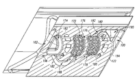
- FIG. 6 is a view of the platform looking radially outward.
- FIG. 6 also shows end portions 130 , 132 , 134 , and 136 of the spanwise passageways. When the cluster main body is initially cast, these passageways are open to the platform underside 140 but are subsequently closed (e.g., by plug welding).
- FIG. 6 further shows covers 160 , 162 , 164 secured (e.g., by welding) to a casting of the cluster.
- Exemplary covers are stamped or lasercut from Ni-based superalloy sheet (e.g., Inconel alloy 625 (UNS N06625)).
- the cover material may be selected for weld and thermal compatibility with the cluster body alloy (e.g., a single crystal Ni-based superalloy casting).
- the exemplary covers 160 , 162 , and 164 cover openings to plenums 170 , 172 , and 174 ( FIG. 7 ).
- the exemplary first plenum 170 is immediately to the pressure side of the first airfoil.
- the exemplary second plenum 172 is immediately to the suction side of the second airfoil and separated from the first plenum by a dividing wall 176 .
- the exemplary third plenum 174 is immediately to the pressure side of the second airfoil.
- these relative positions are characterized when viewed in superposition normal to the airfoil spans.
- the plenums are, however, positioned radially inward of the adjacent airfoil surfaces.
- each of the plenums 170 and 172 feeds an associated subgroup of the outlet holes 120 .
- the plenums may be cast by ceramic cores which may be separately formed from the ceramic feed cores forming the spanwise passageways.
- the holes 120 and their associated outlet passageways 178 (schematically shown in FIG. 6 by their centerlines) from the respective plenums 170 and 172 may be drilled (e.g., via laser drilling or electrodischarge machining (EDM)).
- EDM electrodischarge machining
- the plenum 170 is fed by the first airfoil's spanwise passageways through one or more feed passageways 180 .
- the passageways 180 may be cast in place or may be drilled (e.g., in the same step as the outlet passageways 178 ).
- the plenum 172 is indirectly fed from the second airfoil's spanwise passageways via the plenum 174 .
- feed passageways 182 may be drilled from the plenum 174 to the second airfoil's spanwise passageways.
- FIG. 8 also shows the plenums 170 and 172 as being cast with a plurality of heat transfer pedestals 186 .
- a connector passageway 188 ( FIG. 9 ) joins the plenums 172 and 174 .
- An exemplary connector passageway 188 may be cast in place.
- a single ceramic core is used to cast the plenums 172 and 174 and connector passageway 188 .
- the ceramic core and any additional cores may be overmolded with wax to form a pattern. Upon shelling, previously exposed portions of the ceramic core may become integrated with the shell so as to protrude from an interior surface of the shell that casts the platform inboard surface (of the casting).
- the exemplary connector passageway 188 is positioned to be subsurface to the platform inboard surface (of the casting) whereas the plenums 170 , 172 , and 174 are exposed to the surface and thus must be closed such as by the covers 160 , 162 , and 164 .
- This exposure facilitates chemical decoring.
- the covers may be welded in place (e.g., first by tack welding for positioning then by a full perimeter welding for sealing and structural integrity).
- the covers 160 and 162 are shaped to have two-point contact on either side of a gap 189 . This allows the gap to be aligned with the center of the rib 176 to precisely position the covers and permit the welding.
- the plenum 170 may feed a plenum 190 via a connector passageway 192 .
- An exemplary plenum 190 is positioned along the suction side of the first airfoil near the leading edge thereof.
- the plenums 170 , 190 , and connector passageway 192 may also be cast by a single ceramic core. This may be the same ceramic core that casts the plenums 172 and 174 and their connector passageway 188 or may be separately formed.
- the exemplary plenum 190 feeds the outlet holes 122 via outlet passageways 194 (shown schematically by their centerlines).
- the exemplary plenum 174 feeds the outlet holes 124 via outlet passageways 196 .
- the outlet passageways 194 and 196 may be drilled at the same time as the outlet passageways 178 .
- the passageway network of the exemplary cluster may have one or more of several advantageous properties.
- One advantage is that cooling air is introduced to both platform circumferential ends 86 and 88 . This may be contrasted with a baseline situation wherein cooling air is introduced to only one of the ends. In such a baseline situation, the cooling air from that end will also serve to cool the adjacent other platform end of the adjacent cluster. However, cooling both ends may increase part life.
- Another possible advantage involves the separate feeding of the plenums 170 and 172 .
- the separate feeding of the plenums 170 and 172 reduces the possibilities of adverse interaction between the airflows through the two airfoils. This may be contrasted with a baseline situation wherein a single large plenum between the airfoils is fed with air from both airfoils.
- Such baseline mixing may present engineering problems. For example, it may be desirable to avoid backpressure in the plenum from air flowing from one of the airfoils to interfere with cooling air passing through the other airfoil. Also, the platform area between these plenums and the surface 74 may be subject to different heating considerations.
- the separate feeding may permit a more precise tailoring of airflow properties through each of the sets of passageways 178 .
Landscapes
- Engineering & Computer Science (AREA)
- Mechanical Engineering (AREA)
- General Engineering & Computer Science (AREA)
- Turbine Rotor Nozzle Sealing (AREA)
Abstract
Description
Claims (27)
Priority Applications (4)
| Application Number | Priority Date | Filing Date | Title |
|---|---|---|---|
| US11/412,291 US7625172B2 (en) | 2006-04-26 | 2006-04-26 | Vane platform cooling |
| EP07250726.2A EP1849965B1 (en) | 2006-04-26 | 2007-02-21 | Vane platform cooling |
| JP2007043116A JP2007292052A (en) | 2006-04-26 | 2007-02-23 | Vane cluster and manufacturing method of cluster |
| CNA2007100058036A CN101063411A (en) | 2006-04-26 | 2007-02-25 | Vane platform cooling |
Applications Claiming Priority (1)
| Application Number | Priority Date | Filing Date | Title |
|---|---|---|---|
| US11/412,291 US7625172B2 (en) | 2006-04-26 | 2006-04-26 | Vane platform cooling |
Publications (2)
| Publication Number | Publication Date |
|---|---|
| US20070253816A1 US20070253816A1 (en) | 2007-11-01 |
| US7625172B2 true US7625172B2 (en) | 2009-12-01 |
Family
ID=37930370
Family Applications (1)
| Application Number | Title | Priority Date | Filing Date |
|---|---|---|---|
| US11/412,291 Active 2028-02-09 US7625172B2 (en) | 2006-04-26 | 2006-04-26 | Vane platform cooling |
Country Status (4)
| Country | Link |
|---|---|
| US (1) | US7625172B2 (en) |
| EP (1) | EP1849965B1 (en) |
| JP (1) | JP2007292052A (en) |
| CN (1) | CN101063411A (en) |
Cited By (36)
| Publication number | Priority date | Publication date | Assignee | Title |
|---|---|---|---|---|
| US20110044795A1 (en) * | 2009-08-18 | 2011-02-24 | Chon Young H | Turbine vane platform leading edge cooling holes |
| US20110217155A1 (en) * | 2010-03-03 | 2011-09-08 | Meenakshisundaram Ravichandran | Cooling gas turbine components with seal slot channels |
| US20110236200A1 (en) * | 2010-03-23 | 2011-09-29 | Grover Eric A | Gas turbine engine with non-axisymmetric surface contoured vane platform |
| US20150152735A1 (en) * | 2012-06-15 | 2015-06-04 | General Electric Company | Turbine airfoil with cast platform cooling circuit |
| US9097115B2 (en) | 2011-07-01 | 2015-08-04 | Alstom Technology Ltd | Turbine vane |
| US9579714B1 (en) | 2015-12-17 | 2017-02-28 | General Electric Company | Method and assembly for forming components having internal passages using a lattice structure |
| US9638045B2 (en) | 2014-05-28 | 2017-05-02 | General Electric Company | Cooling structure for stationary blade |
| EP3176283A1 (en) | 2015-12-01 | 2017-06-07 | United Technologies Corporation | Thermal barrier coatings and methods |
| US9771816B2 (en) | 2014-05-07 | 2017-09-26 | General Electric Company | Blade cooling circuit feed duct, exhaust duct, and related cooling structure |
| US9822653B2 (en) | 2015-07-16 | 2017-11-21 | General Electric Company | Cooling structure for stationary blade |
| US9909436B2 (en) | 2015-07-16 | 2018-03-06 | General Electric Company | Cooling structure for stationary blade |
| US9968991B2 (en) | 2015-12-17 | 2018-05-15 | General Electric Company | Method and assembly for forming components having internal passages using a lattice structure |
| US9976433B2 (en) | 2010-04-02 | 2018-05-22 | United Technologies Corporation | Gas turbine engine with non-axisymmetric surface contoured rotor blade platform |
| US9987677B2 (en) | 2015-12-17 | 2018-06-05 | General Electric Company | Method and assembly for forming components having internal passages using a jacketed core |
| US9988916B2 (en) | 2015-07-16 | 2018-06-05 | General Electric Company | Cooling structure for stationary blade |
| US10041374B2 (en) | 2014-04-04 | 2018-08-07 | United Technologies Corporation | Gas turbine engine component with platform cooling circuit |
| US10046389B2 (en) | 2015-12-17 | 2018-08-14 | General Electric Company | Method and assembly for forming components having internal passages using a jacketed core |
| US10099284B2 (en) | 2015-12-17 | 2018-10-16 | General Electric Company | Method and assembly for forming components having a catalyzed internal passage defined therein |
| US10099283B2 (en) | 2015-12-17 | 2018-10-16 | General Electric Company | Method and assembly for forming components having an internal passage defined therein |
| US10099276B2 (en) | 2015-12-17 | 2018-10-16 | General Electric Company | Method and assembly for forming components having an internal passage defined therein |
| US10118217B2 (en) | 2015-12-17 | 2018-11-06 | General Electric Company | Method and assembly for forming components having internal passages using a jacketed core |
| US10137499B2 (en) | 2015-12-17 | 2018-11-27 | General Electric Company | Method and assembly for forming components having an internal passage defined therein |
| US10150158B2 (en) | 2015-12-17 | 2018-12-11 | General Electric Company | Method and assembly for forming components having internal passages using a jacketed core |
| US10215051B2 (en) | 2013-08-20 | 2019-02-26 | United Technologies Corporation | Gas turbine engine component providing prioritized cooling |
| US10227875B2 (en) | 2013-02-15 | 2019-03-12 | United Technologies Corporation | Gas turbine engine component with combined mate face and platform cooling |
| US20190085706A1 (en) * | 2017-09-18 | 2019-03-21 | General Electric Company | Turbine engine airfoil assembly |
| US10286450B2 (en) | 2016-04-27 | 2019-05-14 | General Electric Company | Method and assembly for forming components using a jacketed core |
| US10335853B2 (en) | 2016-04-27 | 2019-07-02 | General Electric Company | Method and assembly for forming components using a jacketed core |
| US10364682B2 (en) | 2013-09-17 | 2019-07-30 | United Technologies Corporation | Platform cooling core for a gas turbine engine rotor blade |
| US10612406B2 (en) | 2018-04-19 | 2020-04-07 | United Technologies Corporation | Seal assembly with shield for gas turbine engines |
| US10689988B2 (en) | 2014-06-12 | 2020-06-23 | Raytheon Technologies Corporation | Disk lug impingement for gas turbine engine airfoil |
| US20200340362A1 (en) * | 2019-04-24 | 2020-10-29 | United Technologies Corporation | Vane core assemblies and methods |
| US11180998B2 (en) | 2018-11-09 | 2021-11-23 | Raytheon Technologies Corporation | Airfoil with skincore passage resupply |
| US11220924B2 (en) | 2019-09-26 | 2022-01-11 | Raytheon Technologies Corporation | Double box composite seal assembly with insert for gas turbine engine |
| US11352897B2 (en) | 2019-09-26 | 2022-06-07 | Raytheon Technologies Corporation | Double box composite seal assembly for gas turbine engine |
| US11359507B2 (en) | 2019-09-26 | 2022-06-14 | Raytheon Technologies Corporation | Double box composite seal assembly with fiber density arrangement for gas turbine engine |
Families Citing this family (22)
| Publication number | Priority date | Publication date | Assignee | Title |
|---|---|---|---|---|
| US8133015B2 (en) * | 2008-09-30 | 2012-03-13 | General Electric Company | Turbine nozzle for a gas turbine engine |
| DE102010005153A1 (en) | 2010-01-21 | 2011-07-28 | MTU Aero Engines GmbH, 80995 | Housing system for an axial flow machine |
| US20120177479A1 (en) * | 2011-01-06 | 2012-07-12 | Gm Salam Azad | Inner shroud cooling arrangement in a gas turbine engine |
| JP5881369B2 (en) * | 2011-10-27 | 2016-03-09 | 三菱重工業株式会社 | Turbine blade and gas turbine provided with the same |
| US9022735B2 (en) * | 2011-11-08 | 2015-05-05 | General Electric Company | Turbomachine component and method of connecting cooling circuits of a turbomachine component |
| US10180067B2 (en) | 2012-05-31 | 2019-01-15 | United Technologies Corporation | Mate face cooling holes for gas turbine engine component |
| US9021816B2 (en) * | 2012-07-02 | 2015-05-05 | United Technologies Corporation | Gas turbine engine turbine vane platform core |
| US9334756B2 (en) | 2012-09-28 | 2016-05-10 | United Technologies Corporation | Liner and method of assembly |
| US9080452B2 (en) | 2012-09-28 | 2015-07-14 | United Technologies Corporation | Gas turbine engine airfoil with vane platform cooling passage |
| EP4019754B1 (en) | 2013-03-15 | 2026-03-11 | RTX Corporation | Acoustic liner with varied properties |
| US9562439B2 (en) * | 2013-12-27 | 2017-02-07 | General Electric Company | Turbine nozzle and method for cooling a turbine nozzle of a gas turbine engine |
| JP6540357B2 (en) | 2015-08-11 | 2019-07-10 | 三菱日立パワーシステムズ株式会社 | Static vane and gas turbine equipped with the same |
| CN105673089B (en) * | 2016-03-31 | 2018-06-29 | 中国船舶重工集团公司第七�三研究所 | A kind of Gas Turbine is without hat gaseous film control rotor blade |
| GB201612646D0 (en) * | 2016-07-21 | 2016-09-07 | Rolls Royce Plc | An air cooled component for a gas turbine engine |
| EP3287596A1 (en) * | 2016-08-25 | 2018-02-28 | Siemens Aktiengesellschaft | A platform cooling device for a blade of a turbomachine and a turbomachine arrangement |
| US20190071978A1 (en) * | 2017-09-01 | 2019-03-07 | United Technologies Corporation | Turbine vane cluster including enhanced platform cooling |
| US11118474B2 (en) | 2017-10-09 | 2021-09-14 | Raytheon Technologies Corporation | Vane cooling structures |
| US10989067B2 (en) * | 2018-07-13 | 2021-04-27 | Honeywell International Inc. | Turbine vane with dust tolerant cooling system |
| US11156116B2 (en) * | 2019-04-08 | 2021-10-26 | Honeywell International Inc. | Turbine nozzle with reduced leakage feather seals |
| US11230929B2 (en) | 2019-11-05 | 2022-01-25 | Honeywell International Inc. | Turbine component with dust tolerant cooling system |
| US11459895B2 (en) * | 2020-04-14 | 2022-10-04 | Raytheon Technologies Corporation | Turbine blade cooling hole for side wall |
| CN112282860A (en) * | 2020-11-17 | 2021-01-29 | 西安热工研究院有限公司 | A cooling structure for turbine rotor blade platform |
Citations (5)
| Publication number | Priority date | Publication date | Assignee | Title |
|---|---|---|---|---|
| US5344283A (en) | 1993-01-21 | 1994-09-06 | United Technologies Corporation | Turbine vane having dedicated inner platform cooling |
| US5413458A (en) | 1994-03-29 | 1995-05-09 | United Technologies Corporation | Turbine vane with a platform cavity having a double feed for cooling fluid |
| US5997245A (en) * | 1997-04-24 | 1999-12-07 | Mitsubishi Heavy Industries, Ltd. | Cooled shroud of gas turbine stationary blade |
| US20050058545A1 (en) * | 2003-09-12 | 2005-03-17 | Siemens Westinghouse Power Corporation | Turbine blade platform cooling system |
| US20050135923A1 (en) | 2003-12-22 | 2005-06-23 | Todd Coons | Cooled vane cluster |
Family Cites Families (8)
| Publication number | Priority date | Publication date | Assignee | Title |
|---|---|---|---|---|
| US4353679A (en) * | 1976-07-29 | 1982-10-12 | General Electric Company | Fluid-cooled element |
| US4218178A (en) * | 1978-03-31 | 1980-08-19 | General Motors Corporation | Turbine vane structure |
| FR2723144B1 (en) * | 1984-11-29 | 1996-12-13 | Snecma | TURBINE DISTRIBUTOR |
| JPH0552102A (en) * | 1991-08-23 | 1993-03-02 | Toshiba Corp | Gas turbine |
| US5634766A (en) * | 1994-08-23 | 1997-06-03 | General Electric Co. | Turbine stator vane segments having combined air and steam cooling circuits |
| US6065928A (en) * | 1998-07-22 | 2000-05-23 | General Electric Company | Turbine nozzle having purge air circuit |
| DE10016081A1 (en) * | 2000-03-31 | 2001-10-04 | Alstom Power Nv | Plate-shaped, projecting component section of a gas turbine |
| JP4508482B2 (en) * | 2001-07-11 | 2010-07-21 | 三菱重工業株式会社 | Gas turbine stationary blade |
-
2006
- 2006-04-26 US US11/412,291 patent/US7625172B2/en active Active
-
2007
- 2007-02-21 EP EP07250726.2A patent/EP1849965B1/en active Active
- 2007-02-23 JP JP2007043116A patent/JP2007292052A/en active Pending
- 2007-02-25 CN CNA2007100058036A patent/CN101063411A/en active Pending
Patent Citations (5)
| Publication number | Priority date | Publication date | Assignee | Title |
|---|---|---|---|---|
| US5344283A (en) | 1993-01-21 | 1994-09-06 | United Technologies Corporation | Turbine vane having dedicated inner platform cooling |
| US5413458A (en) | 1994-03-29 | 1995-05-09 | United Technologies Corporation | Turbine vane with a platform cavity having a double feed for cooling fluid |
| US5997245A (en) * | 1997-04-24 | 1999-12-07 | Mitsubishi Heavy Industries, Ltd. | Cooled shroud of gas turbine stationary blade |
| US20050058545A1 (en) * | 2003-09-12 | 2005-03-17 | Siemens Westinghouse Power Corporation | Turbine blade platform cooling system |
| US20050135923A1 (en) | 2003-12-22 | 2005-06-23 | Todd Coons | Cooled vane cluster |
Cited By (48)
| Publication number | Priority date | Publication date | Assignee | Title |
|---|---|---|---|---|
| US20110044795A1 (en) * | 2009-08-18 | 2011-02-24 | Chon Young H | Turbine vane platform leading edge cooling holes |
| US8353669B2 (en) * | 2009-08-18 | 2013-01-15 | United Technologies Corporation | Turbine vane platform leading edge cooling holes |
| JP2011179500A (en) * | 2010-03-03 | 2011-09-15 | General Electric Co <Ge> | Cooling gas turbine components with seal slot channels |
| US8371800B2 (en) | 2010-03-03 | 2013-02-12 | General Electric Company | Cooling gas turbine components with seal slot channels |
| US20110217155A1 (en) * | 2010-03-03 | 2011-09-08 | Meenakshisundaram Ravichandran | Cooling gas turbine components with seal slot channels |
| US20110236200A1 (en) * | 2010-03-23 | 2011-09-29 | Grover Eric A | Gas turbine engine with non-axisymmetric surface contoured vane platform |
| US8356975B2 (en) | 2010-03-23 | 2013-01-22 | United Technologies Corporation | Gas turbine engine with non-axisymmetric surface contoured vane platform |
| US9976433B2 (en) | 2010-04-02 | 2018-05-22 | United Technologies Corporation | Gas turbine engine with non-axisymmetric surface contoured rotor blade platform |
| US9097115B2 (en) | 2011-07-01 | 2015-08-04 | Alstom Technology Ltd | Turbine vane |
| US10738621B2 (en) | 2012-06-15 | 2020-08-11 | General Electric Company | Turbine airfoil with cast platform cooling circuit |
| US20150152735A1 (en) * | 2012-06-15 | 2015-06-04 | General Electric Company | Turbine airfoil with cast platform cooling circuit |
| US10100647B2 (en) * | 2012-06-15 | 2018-10-16 | General Electric Company | Turbine airfoil with cast platform cooling circuit |
| US10227875B2 (en) | 2013-02-15 | 2019-03-12 | United Technologies Corporation | Gas turbine engine component with combined mate face and platform cooling |
| US10215051B2 (en) | 2013-08-20 | 2019-02-26 | United Technologies Corporation | Gas turbine engine component providing prioritized cooling |
| US10364682B2 (en) | 2013-09-17 | 2019-07-30 | United Technologies Corporation | Platform cooling core for a gas turbine engine rotor blade |
| US10907481B2 (en) | 2013-09-17 | 2021-02-02 | Raytheon Technologies Corporation | Platform cooling core for a gas turbine engine rotor blade |
| US10041374B2 (en) | 2014-04-04 | 2018-08-07 | United Technologies Corporation | Gas turbine engine component with platform cooling circuit |
| US9771816B2 (en) | 2014-05-07 | 2017-09-26 | General Electric Company | Blade cooling circuit feed duct, exhaust duct, and related cooling structure |
| US9638045B2 (en) | 2014-05-28 | 2017-05-02 | General Electric Company | Cooling structure for stationary blade |
| US10689988B2 (en) | 2014-06-12 | 2020-06-23 | Raytheon Technologies Corporation | Disk lug impingement for gas turbine engine airfoil |
| US9909436B2 (en) | 2015-07-16 | 2018-03-06 | General Electric Company | Cooling structure for stationary blade |
| US9988916B2 (en) | 2015-07-16 | 2018-06-05 | General Electric Company | Cooling structure for stationary blade |
| US9822653B2 (en) | 2015-07-16 | 2017-11-21 | General Electric Company | Cooling structure for stationary blade |
| US10436042B2 (en) | 2015-12-01 | 2019-10-08 | United Technologies Corporation | Thermal barrier coatings and methods |
| EP3176283A1 (en) | 2015-12-01 | 2017-06-07 | United Technologies Corporation | Thermal barrier coatings and methods |
| US10099284B2 (en) | 2015-12-17 | 2018-10-16 | General Electric Company | Method and assembly for forming components having a catalyzed internal passage defined therein |
| US10118217B2 (en) | 2015-12-17 | 2018-11-06 | General Electric Company | Method and assembly for forming components having internal passages using a jacketed core |
| US10137499B2 (en) | 2015-12-17 | 2018-11-27 | General Electric Company | Method and assembly for forming components having an internal passage defined therein |
| US10150158B2 (en) | 2015-12-17 | 2018-12-11 | General Electric Company | Method and assembly for forming components having internal passages using a jacketed core |
| US10099276B2 (en) | 2015-12-17 | 2018-10-16 | General Electric Company | Method and assembly for forming components having an internal passage defined therein |
| US9968991B2 (en) | 2015-12-17 | 2018-05-15 | General Electric Company | Method and assembly for forming components having internal passages using a lattice structure |
| US9579714B1 (en) | 2015-12-17 | 2017-02-28 | General Electric Company | Method and assembly for forming components having internal passages using a lattice structure |
| US9987677B2 (en) | 2015-12-17 | 2018-06-05 | General Electric Company | Method and assembly for forming components having internal passages using a jacketed core |
| US10099283B2 (en) | 2015-12-17 | 2018-10-16 | General Electric Company | Method and assembly for forming components having an internal passage defined therein |
| US10046389B2 (en) | 2015-12-17 | 2018-08-14 | General Electric Company | Method and assembly for forming components having internal passages using a jacketed core |
| US9975176B2 (en) | 2015-12-17 | 2018-05-22 | General Electric Company | Method and assembly for forming components having internal passages using a lattice structure |
| US10286450B2 (en) | 2016-04-27 | 2019-05-14 | General Electric Company | Method and assembly for forming components using a jacketed core |
| US10335853B2 (en) | 2016-04-27 | 2019-07-02 | General Electric Company | Method and assembly for forming components using a jacketed core |
| US10981221B2 (en) | 2016-04-27 | 2021-04-20 | General Electric Company | Method and assembly for forming components using a jacketed core |
| US20190085706A1 (en) * | 2017-09-18 | 2019-03-21 | General Electric Company | Turbine engine airfoil assembly |
| US10612406B2 (en) | 2018-04-19 | 2020-04-07 | United Technologies Corporation | Seal assembly with shield for gas turbine engines |
| US11180998B2 (en) | 2018-11-09 | 2021-11-23 | Raytheon Technologies Corporation | Airfoil with skincore passage resupply |
| US20200340362A1 (en) * | 2019-04-24 | 2020-10-29 | United Technologies Corporation | Vane core assemblies and methods |
| US11021966B2 (en) * | 2019-04-24 | 2021-06-01 | Raytheon Technologies Corporation | Vane core assemblies and methods |
| US11220924B2 (en) | 2019-09-26 | 2022-01-11 | Raytheon Technologies Corporation | Double box composite seal assembly with insert for gas turbine engine |
| US11352897B2 (en) | 2019-09-26 | 2022-06-07 | Raytheon Technologies Corporation | Double box composite seal assembly for gas turbine engine |
| US11359507B2 (en) | 2019-09-26 | 2022-06-14 | Raytheon Technologies Corporation | Double box composite seal assembly with fiber density arrangement for gas turbine engine |
| US11732597B2 (en) | 2019-09-26 | 2023-08-22 | Raytheon Technologies Corporation | Double box composite seal assembly with insert for gas turbine engine |
Also Published As
| Publication number | Publication date |
|---|---|
| CN101063411A (en) | 2007-10-31 |
| EP1849965B1 (en) | 2015-02-18 |
| US20070253816A1 (en) | 2007-11-01 |
| JP2007292052A (en) | 2007-11-08 |
| EP1849965A3 (en) | 2011-05-18 |
| EP1849965A2 (en) | 2007-10-31 |
Similar Documents
| Publication | Publication Date | Title |
|---|---|---|
| US7625172B2 (en) | Vane platform cooling | |
| EP1916388B1 (en) | Vane with enhanced heat transfer | |
| US8206108B2 (en) | Turbine blades and methods of manufacturing | |
| JP2007198377A (en) | Cooled cast component, cooled component manufacturing method, cast component surface cooling method, and gas turbine engine air foil structural element | |
| US10196917B2 (en) | Blade outer air seal with cored passages | |
| EP1801351B1 (en) | Turbine blade tip cooling | |
| JP4658584B2 (en) | Inner cooling nozzle doublet | |
| EP3034808B1 (en) | Casting core for blade outer air seal, blade outer air seal and corresponding manufacturing method | |
| US9021816B2 (en) | Gas turbine engine turbine vane platform core | |
| US20240102392A1 (en) | Component for a turbine engine with a cooling hole | |
| US9238970B2 (en) | Blade outer air seal assembly leading edge core configuration | |
| US10415403B2 (en) | Cooled blisk for gas turbine engine | |
| US10247015B2 (en) | Cooled blisk with dual wall blades for gas turbine engine | |
| US20190316472A1 (en) | Double wall airfoil cooling configuration for gas turbine engine | |
| EP3730742B1 (en) | Gas turbine engine and method for manufacturing | |
| US10024190B1 (en) | Apparatus and process for forming an air cooled turbine airfoil with a cooling air channel and discharge slot in a thin wall | |
| EP4450761A1 (en) | Airfoil element, gas turbine engine, method for manufacturing an airfoil element, method for using an airfoil element, airfoil element and casting core assembly for casting an airfoil element | |
| US12497896B2 (en) | Airfoil assembly with platform film holes | |
| EP4428338A2 (en) | Turbine engine airfoils with film cooling and method of manufacturing | |
| CN118774980A (en) | Engine component having a cooling supply circuit |
Legal Events
| Date | Code | Title | Description |
|---|---|---|---|
| AS | Assignment |
Owner name: UNITED TECHNOLOGIES CORPORATION, CONNECTICUT Free format text: ASSIGNMENT OF ASSIGNORS INTEREST;ASSIGNORS:WALZ, CHRISTOPHER S.;WASSERMAN, DAVID J.;WONG, ALEX D.;AND OTHERS;REEL/FRAME:017628/0318 Effective date: 20060515 |
|
| STCF | Information on status: patent grant |
Free format text: PATENTED CASE |
|
| AS | Assignment |
Owner name: AIR FORCE, THE UNITED STATES OF AMERICA AS REPRESE Free format text: EXEUTIVE ORDER 9424, CONFIRMATORY LICENSE;ASSIGNOR:UNITED TECHNOLOGIES CORPORATION;REEL/FRAME:025154/0764 Effective date: 20061130 |
|
| CC | Certificate of correction | ||
| FPAY | Fee payment |
Year of fee payment: 4 |
|
| FPAY | Fee payment |
Year of fee payment: 8 |
|
| AS | Assignment |
Owner name: RAYTHEON TECHNOLOGIES CORPORATION, MASSACHUSETTS Free format text: CHANGE OF NAME;ASSIGNOR:UNITED TECHNOLOGIES CORPORATION;REEL/FRAME:054062/0001 Effective date: 20200403 |
|
| AS | Assignment |
Owner name: RAYTHEON TECHNOLOGIES CORPORATION, CONNECTICUT Free format text: CORRECTIVE ASSIGNMENT TO CORRECT THE AND REMOVE PATENT APPLICATION NUMBER 11886281 AND ADD PATENT APPLICATION NUMBER 14846874. TO CORRECT THE RECEIVING PARTY ADDRESS PREVIOUSLY RECORDED AT REEL: 054062 FRAME: 0001. ASSIGNOR(S) HEREBY CONFIRMS THE CHANGE OF ADDRESS;ASSIGNOR:UNITED TECHNOLOGIES CORPORATION;REEL/FRAME:055659/0001 Effective date: 20200403 |
|
| MAFP | Maintenance fee payment |
Free format text: PAYMENT OF MAINTENANCE FEE, 12TH YEAR, LARGE ENTITY (ORIGINAL EVENT CODE: M1553); ENTITY STATUS OF PATENT OWNER: LARGE ENTITY Year of fee payment: 12 |
|
| AS | Assignment |
Owner name: RTX CORPORATION, CONNECTICUT Free format text: CHANGE OF NAME;ASSIGNOR:RAYTHEON TECHNOLOGIES CORPORATION;REEL/FRAME:064714/0001 Effective date: 20230714 |