EP1849965A2 - Vane platform cooling - Google Patents
Vane platform cooling Download PDFInfo
- Publication number
- EP1849965A2 EP1849965A2 EP07250726A EP07250726A EP1849965A2 EP 1849965 A2 EP1849965 A2 EP 1849965A2 EP 07250726 A EP07250726 A EP 07250726A EP 07250726 A EP07250726 A EP 07250726A EP 1849965 A2 EP1849965 A2 EP 1849965A2
- Authority
- EP
- European Patent Office
- Prior art keywords
- platform
- airfoil
- shroud
- cooling
- passageway
- Prior art date
- Legal status (The legal status is an assumption and is not a legal conclusion. Google has not performed a legal analysis and makes no representation as to the accuracy of the status listed.)
- Granted
Links
Images


Classifications
-
- F—MECHANICAL ENGINEERING; LIGHTING; HEATING; WEAPONS; BLASTING
- F01—MACHINES OR ENGINES IN GENERAL; ENGINE PLANTS IN GENERAL; STEAM ENGINES
- F01D—NON-POSITIVE DISPLACEMENT MACHINES OR ENGINES, e.g. STEAM TURBINES
- F01D5/00—Blades; Blade-carrying members; Heating, heat-insulating, cooling or antivibration means on the blades or the members
- F01D5/12—Blades
- F01D5/14—Form or construction
- F01D5/18—Hollow blades, i.e. blades with cooling or heating channels or cavities; Heating, heat-insulating or cooling means on blades
- F01D5/186—Film cooling
-
- F—MECHANICAL ENGINEERING; LIGHTING; HEATING; WEAPONS; BLASTING
- F01—MACHINES OR ENGINES IN GENERAL; ENGINE PLANTS IN GENERAL; STEAM ENGINES
- F01D—NON-POSITIVE DISPLACEMENT MACHINES OR ENGINES, e.g. STEAM TURBINES
- F01D25/00—Component parts, details, or accessories, not provided for in, or of interest apart from, other groups
- F01D25/08—Cooling; Heating; Heat-insulation
- F01D25/12—Cooling
-
- F—MECHANICAL ENGINEERING; LIGHTING; HEATING; WEAPONS; BLASTING
- F05—INDEXING SCHEMES RELATING TO ENGINES OR PUMPS IN VARIOUS SUBCLASSES OF CLASSES F01-F04
- F05D—INDEXING SCHEME FOR ASPECTS RELATING TO NON-POSITIVE-DISPLACEMENT MACHINES OR ENGINES, GAS-TURBINES OR JET-PROPULSION PLANTS
- F05D2240/00—Components
- F05D2240/80—Platforms for stationary or moving blades
- F05D2240/81—Cooled platforms
-
- Y—GENERAL TAGGING OF NEW TECHNOLOGICAL DEVELOPMENTS; GENERAL TAGGING OF CROSS-SECTIONAL TECHNOLOGIES SPANNING OVER SEVERAL SECTIONS OF THE IPC; TECHNICAL SUBJECTS COVERED BY FORMER USPC CROSS-REFERENCE ART COLLECTIONS [XRACs] AND DIGESTS
- Y02—TECHNOLOGIES OR APPLICATIONS FOR MITIGATION OR ADAPTATION AGAINST CLIMATE CHANGE
- Y02T—CLIMATE CHANGE MITIGATION TECHNOLOGIES RELATED TO TRANSPORTATION
- Y02T50/00—Aeronautics or air transport
- Y02T50/60—Efficient propulsion technologies, e.g. for aircraft
Landscapes
- Engineering & Computer Science (AREA)
- Mechanical Engineering (AREA)
- General Engineering & Computer Science (AREA)
- Turbine Rotor Nozzle Sealing (AREA)
Abstract
Description
- The invention relates to cooling of high temperature components. More particularly, the invention relates to film cooling of gas turbine engine components.
- In the aerospace industry, a well-developed art exists regarding the cooling of components such as gas turbine engine components. Exemplary components are gas turbine engine blades and vanes. Exemplary blades and vanes airfoils are cooled by airflow directed through the airfoil to be discharged from cooling holes in the airfoil surface. Also, there may be cooling holes along the vane shroud or vane or blade platform. The cooling mechanisms may include both direct cooling as the airflow passes through the component and film cooling after the airflow has been discharged from the component but passes downstream close to the component exterior surface.
- By way of example, cooled vanes are found in
U.S. Patents 5413458 and5344283 andU.S. Application Publication 20050135923 . Exemplary cooled vanes are formed by an investment casting process. A sacrificial material (e.g., wax) is molded over one or more cores (e.g., refractory metal cores and/or ceramic cores) to form a pattern. The pattern is shelled. The shell is dewaxed. Alloy (e.g., nickel- or cobalt- based superalloy) is cast in the shell. The shell and core(s) may be destructively removed (e.g., by mechanical means and chemical means, respectively). The casting may be finish machined (including surface machining and drilling of holes/passageways). The casting may be coated with a thermal and/or erosion-resistant coating. - Accordingly, one aspect of the invention involves a vane cluster having a platform, a shroud, and at least first and second airfoils extending between an outer face of the platform and an inner face of the shroud. Each airfoil has a pressure side and a suction side. The pressure side of the first airfoil faces the suction side of the second airfoil. The cluster includes a cooling passageway system. The system includes at least one inlet in the shroud. At least one first feed passageway extends from the shroud to the platform through the first airfoil. At least one second feed passageway extends from the shroud to the platform through the second airfoil. A first platform cooling plenum is to the pressure side of the first airfoil. A second platform cooling plenum is to the suction side of the first airfoil.
- In various implementations, the cluster may include a casting essentially forming the shroud, airfoils, and a majority of the platform. The cluster may include one or more covers enclosing the first and second platform cooling plenums.
- The details of one or more embodiments of the invention are set forth in the accompanying drawings and the description below. Other features and advantages of the invention will be apparent from the description and drawings, and from the claims.
-
- FIG. 1 is a schematic view of a gas turbine engine.
- FIG. 2 is a view of a vane ring of the engine of FIG. 1.
- FIG. 3 is a view of a vane cluster of the ring of FIG. 2.
- FIG. 4 is a first view of a platform of the cluster of FIG. 3.
- FIG. 5 is a second view of the platform of the cluster of FIG. 3.
- FIG. 6 is an underside view of the cluster of FIG. 3.
- FIG. 7 is a cross-sectional view of the cluster of FIG. 6 taken along line 7-7.
- FIG. 8 is a view of the underside of the cluster of FIG. 3 with covers removed.
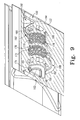
- FIG. 9 is a cross-sectional view of the cluster of FIG. 3 taken along line 9-9.
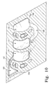
- FIG. 10 is a cross-sectional view of the cluster of FIG. 3 taken along line 10-10.
- Like reference numbers and designations in the various drawings indicate like elements.
- FIG. 1 shows a
gas turbine engine 20 having a centrallongitudinal axis 500 and extending from anupstream inlet 22 to adownstream outlet 24. From upstream to downstream, the engine may have a number of sections along a core flowpath. From upstream to downstream, the sections may include a low speed/pressure compressor (LPC) 30, a high speed/pressure compressor (HPC) 32, acombustor 34, a high speed/pressure turbine (HPT) 36, a low speed/pressure turbine (LPT) 38, anaugmentor 40, and an exhaust duct/nozzle 42. Each of the compressor and turbine sections may include a number of blade stages interspersed with a number of vane stages. The blades of the LPC and LPT are mounted on a low speed spool for rotation about theaxis 500. The blades of the HPC and HPT are mounted on a high speed spool for such rotation. - As is discussed in further detail below, one or more of the vane stages may be formed as a cluster ring. For example, a
second vane stage 50 of the HPT 36 is schematically shown in FIG. 1. FIG. 2 shows further details of theexemplary vane stage 50. The ring includes aninboard platform 52 and anoutboard shroud 54. A circumferential array of airfoils (discussed below) span between the platform and shroud. As is discussed in further detail below, the ring may be segmented into a plurality of separately-formed clusters interlocked at the platforms by astructural ring 56 and at the shrouds by an engine case. - FIG. 3 shows an exemplary two-
airfoil cluster 60. Each exemplary cluster includes afirst airfoil 62 and asecond airfoil 64. Each of the airfoils extends from an associatedinboard end 66 at aplatform segment 68 to an associatedoutboard end 70 at ashroud segment 72. The exemplary platform segment has anoutboard surface 74 along the inboard extreme of the core flowpath. The shroud segment has aninboard surface 76 along an outboard extreme of the core flowpath. - An
underside 80 of the platform segment may include features for mounting each platform segment to its adjacent segments (e.g., by bolting to the ring 56). The platform segment has a forward/upstream end 82, a rear/downstream end 84, and first and second circumferential ends ormatefaces shroud segment 72 has anupstream end 92, adownstream end 94, and first and secondcircumferential ends circumferential ends adjacent grooves features - The
cluster 60 has cooling passageways. An exemplary passageway network may include one ormore inlet ports shroud segment 72. Theports airfoils platform segment 68 to provide platform cooling. Such air may exit the platform through one or more outlet holes. For example, FIGS. 4 and 5 show outlet holes 120 along the platformoutboard surface 74. FIGS. 4 and 5, respectively, also show outlet holes 122 and 124 along the platform circumferential ends 86 and 88. - FIG. 6 is a view of the platform looking radially outward. FIG. 6 also shows
end portions platform underside 140 but are subsequently closed (e.g., by plug welding). FIG. 6. further shows covers 160, 162, 164 secured (e.g., by welding) to a casting of the cluster. Exemplary covers are stamped or lasercut from Ni-based superalloy sheet (e.g., Inconel alloy 625 (UNS N06625)). The cover material may be selected for weld and thermal compatibility with the cluster body alloy (e.g., a single crystal Ni-based superalloy casting). The exemplary covers 160, 162, and 164 cover openings toplenums first plenum 170 is immediately to the pressure side of the first airfoil. The exemplarysecond plenum 172 is immediately to the suction side of the second airfoil and separated from the first plenum by a dividingwall 176. The exemplarythird plenum 174 is immediately to the pressure side of the second airfoil. For reference, these relative positions are characterized when viewed in superposition normal to the airfoil spans. The plenums are, however, positioned radially inward of the adjacent airfoil surfaces. - In the exemplary cluster, each of the
plenums holes 120 and their associated outlet passageways 178 (schematically shown in FIG. 6 by their centerlines) from therespective plenums plenum 170 is fed by the first airfoil's spanwise passageways through one ormore feed passageways 180. Thepassageways 180 may be cast in place or may be drilled (e.g., in the same step as the outlet passageways 178). In the exemplary cluster, theplenum 172 is indirectly fed from the second airfoil's spanwise passageways via theplenum 174. In the particular example, feedpassageways 182 may be drilled from theplenum 174 to the second airfoil's spanwise passageways. - FIG. 8 also shows the
plenums plenums exemplary connector passageway 188 may be cast in place. In an exemplary method of manufacture, a single ceramic core is used to cast theplenums connector passageway 188. In the investment casting process, the ceramic core and any additional cores may be overmolded with wax to form a pattern. Upon shelling, previously exposed portions of the ceramic core may become integrated with the shell so as to protrude from an interior surface of the shell that casts the platform inboard surface (of the casting). Theexemplary connector passageway 188 is positioned to be subsurface to the platform inboard surface (of the casting) whereas theplenums covers covers gap 189. This allows the gap to be aligned with the center of therib 176 to precisely position the covers and permit the welding. - In a similar fashion, the
plenum 170 may feed aplenum 190 via aconnector passageway 192. Anexemplary plenum 190 is positioned along the suction side of the first airfoil near the leading edge thereof. Theplenums connector passageway 192 may also be cast by a single ceramic core. This may be the same ceramic core that casts theplenums connector passageway 188 or may be separately formed. - Use of the
connector passageway 188 facilitates drilling of the feed passageways from theplenum 174 rather than from theplenum 172. The former may present easier drill access. Theexemplary plenum 190 feeds the outlet holes 122 via outlet passageways 194 (shown schematically by their centerlines). Theexemplary plenum 174 feeds the outlet holes 124 viaoutlet passageways 196. The outlet passageways 194 and 196 may be drilled at the same time as theoutlet passageways 178. - The passageway network of the exemplary cluster may have one or more of several advantageous properties. One advantage is that cooling air is introduced to both platform circumferential ends 86 and 88. This may be contrasted with a baseline situation wherein cooling air is introduced to only one of the ends. In such a baseline situation, the cooling air from that end will also serve to cool the adjacent other platform end of the adjacent cluster. However, cooling both ends may increase part life.
- Another possible advantage involves the separate feeding of the
plenums plenums surface 74 may be subject to different heating considerations. The separate feeding may permit a more precise tailoring of airflow properties through each of the sets ofpassageways 178. - One or more embodiments of the present invention have been described. Nevertheless, it will be understood that various modifications may be made without departing from the scope of the invention. For example, the principles may be applied in the remanufacturing of an existing engine or the reengineering of an existing baseline engine configuration. In such a remanufacturing or reengineering situation, details of the baseline configuration may influence details of the particular implementation. Accordingly, other embodiments are within the scope of the following claims.
Claims (19)
- A vane cluster (60) comprising:a platform (68);a shroud (72);at least first and second airfoils (62, 64) extending between an outer face (74) of the platform (68) and an inner face (76) of the shroud (72), each airfoil (62, 64) having a pressure side and a suction side, the pressure side of the first airfoil (62) facing the suction side of the second airfoil (64); anda cooling passageway system,wherein:the cooling passageway system includes:at least one inlet (110, 112) in the shroud (72);at least one first feed passageway from the shroud (72) to the platform (68) through the first airfoil (62);at least one second feed passageway from the shroud (72) to the platform (68) through the second airfoil (64);a first platform cooling plenum (170) to the pressure side of the first airfoil (62); anda second platform cooling plenum (190) to the suction side of the first airfoil (62).
- The cluster of claim 1 wherein:the cooling passageway system includes:first and second pluralities of outlet holes (122, 124) extending to first and second circumferential ends of the platform (68).
- The cluster of claim 1 or 2 wherein:the first platform cooling plenum (170) is coupled to the at least one first feed passageway; andthe second platform cooling plenum (190) is coupled to the at least one first feed passageway via the first platform cooling plenum (170) and a connector (192).
- The cluster of any preceding claim wherein:a third platform cooling plenum (172) is located to the suction side of the second airfoil (64) and coupled to the at least one second feed passageway.
- A method for manufacturing the cluster of claim 1 comprising:manufacturing a casting by an investment casting process, the casting including precursors of the platform (68), shroud (72), first and second airfoils (62, 64), first and second feed passageways, and first and second platform cooling plenums (170, 190); andsecuring at least one cover (160) over the first platform cooling plenum (170).
- The method of claim 5 wherein:the investment casting uses first and second feed cores to cast the first and second feed passageways and a single separate core for casting the first and second platform cooling plenums (170, 190); andin the as-cast casting, the first platform cooling plenum precursor is open along an inboard surface of the platform precursor, but the second platform cooling plenum precursor is subsurface to said inboard surface.
- A vane cluster (60) comprising:a platform (68);a shroud (72);at least first and second airfoils (62, 64) extending between an outer face (74) of the platform (68) and an inner face (76) of the shroud (72), each airfoil (62, 64) having a pressure side and a suction side, the pressure side of the first airfoil (62) facing the suction side of the second airfoil (64); anda cooling passageway system,wherein:the cooling passageway system includes:at least one inlet (110, 112) in the shroud (72);at least one first feed passageway from the shroud (72) to the platform (68) through the first airfoil (62);at least one second feed passageway from the shroud (72) to the platform (68) through the second airfoil (64);a first platform cooling plenum (190) to the suction side of the first airfoil (62); anda second platform cooling plenum (174) to the pressure side of the second airfoil (64).
- The cluster of claim 7 wherein:a plurality of first outlet passageways (194) extend from the first platform cooling plenum (190) to a first circumferential end (86) of the platform (68); anda plurality of second outlet passageways (196) extend from the second platform cooling plenum (174) to a second circumferential end (88) of the platform (68).
- The cluster of claim 7 or 8 wherein:the cooling passageway system further includes:a third platform cooling plenum (170; 172) between the first and second airfoils (62, 64).
- The cluster of claim 7 or 8 wherein:the cooling passageway system further includes:third and fourth platform cooling plenums (170, 172) between the first and second airfoils (62, 64).
- The cluster of claim 10 wherein:a first connector passageway (192) in the platform (68) is positioned to feed the first platform cooling plenum (190) from the third platform cooling plenum (170); anda second connector passageway (188) in the platform (68) is positioned to feed the fourth platform cooling plenum (172) from the second platform cooling plenum (174).
- The cluster of claim 11 wherein:at least one first feeder hole extends from the at least one first feed passageway to the third platform cooling plenum (170); andat least one second feeder hole extends from the at least one second feed passageway to the second platform cooling plenum (174).
- The cluster of claim 11 or 12 comprising:a casting, essentially forming the airfoils (62, 64) and at least main body portions of the platform (68) and shroud (72); andthree cover plates (164, 160, 162) welded to the platform main body portion to respectively enclose the second, third, and fourth platform cooling plenums (174, 170, 172), the first cooling plenum (190) being internal to the casting.
- A method for manufacturing the cluster of claim 7 comprising:manufacturing a casting by an investment casting process, the casting including precursors of the platform (68), shroud (72), first and second airfoils (62, 64), first and second feed passageways, and first and second platform cooling plenums (190, 174); andsecuring at least one cover over the first and second platform cooling plenums (190, 174).
- The method of claim 14 wherein:the investment casting uses first and second feed cores to cast the first and second feed passageways and at least one separate core for casting the first and second platform cooling plenums (190, 174); andin the as-cast casting, the first and second platform cooling plenum precursors are open along an inboard surface of the platform precursor.
- A vane cluster (10) comprising:a platform (68);a shroud (72);at least first and second airfoils (62, 64) extending between an outer face (74) of the platform (68) and an inner face (76) of the shroud (72), each airfoil having a pressure side and a suction side, the pressure side of the first airfoil (62) facing the suction side of the second airfoil (64); anda cooling passageway system,wherein:the cooling passageway system includes:at least one inlet (110, 112) in the shroud;at least one first feed passageway from the shroud (72) to the platform (68) through the first airfoil (62);at least one second feed passageway from the shroud (72) to the platform (68) through the second airfoil (64);a first platform cooling plenum (174) to the pressure side of the second airfoil (64); anda second platform cooling plenum (172) to the suction side of the second airfoil (64); anda connector passageway (188), connecting the first platform cooling plenum (174) to the second platform cooling plenum (172).
- The cluster of claim 16 wherein:a plurality of first outlet passageways (196) extend from the first platform cooling plenum (174) to an adjacent circumferential end (88) of the platform (68); andthe connector passageway (188) extends around a trailing edge of the second airfoil (64).
- A method for manufacturing the cluster of claim 16 comprising:manufacturing a casting by an investment casting process, the casting including precursors of the platform (68), shroud (72), first and second airfoils (62, 64), first and second feed passageways, and first and second platform cooling plenums (174, 172); andsecuring at least one cover (164, 162) over the first and second platform cooling plenums (174, 172).
- The method of claim 18 wherein:the investment casting uses first and second feed cores to cast the first and second feed passageways and at least one separate core for casting the first and second platform cooling plenums (174, 172); andin the as-cast casting, the first and second platform cooling plenum precursors are open along an inboard surface of the platform precursor and the connector passageway (188) is subsurface.
Applications Claiming Priority (1)
| Application Number | Priority Date | Filing Date | Title |
|---|---|---|---|
| US11/412,291 US7625172B2 (en) | 2006-04-26 | 2006-04-26 | Vane platform cooling |
Publications (3)
| Publication Number | Publication Date |
|---|---|
| EP1849965A2 true EP1849965A2 (en) | 2007-10-31 |
| EP1849965A3 EP1849965A3 (en) | 2011-05-18 |
| EP1849965B1 EP1849965B1 (en) | 2015-02-18 |
Family
ID=37930370
Family Applications (1)
| Application Number | Title | Priority Date | Filing Date |
|---|---|---|---|
| EP07250726.2A Active EP1849965B1 (en) | 2006-04-26 | 2007-02-21 | Vane platform cooling |
Country Status (4)
| Country | Link |
|---|---|
| US (1) | US7625172B2 (en) |
| EP (1) | EP1849965B1 (en) |
| JP (1) | JP2007292052A (en) |
| CN (1) | CN101063411A (en) |
Cited By (17)
| Publication number | Priority date | Publication date | Assignee | Title |
|---|---|---|---|---|
| US9057274B2 (en) | 2010-01-21 | 2015-06-16 | Mtu Aero Engines Gmbh | Housing system for an axial turbomachine |
| US9579714B1 (en) | 2015-12-17 | 2017-02-28 | General Electric Company | Method and assembly for forming components having internal passages using a lattice structure |
| US9968991B2 (en) | 2015-12-17 | 2018-05-15 | General Electric Company | Method and assembly for forming components having internal passages using a lattice structure |
| US9987677B2 (en) | 2015-12-17 | 2018-06-05 | General Electric Company | Method and assembly for forming components having internal passages using a jacketed core |
| US10046389B2 (en) | 2015-12-17 | 2018-08-14 | General Electric Company | Method and assembly for forming components having internal passages using a jacketed core |
| US10099283B2 (en) | 2015-12-17 | 2018-10-16 | General Electric Company | Method and assembly for forming components having an internal passage defined therein |
| US10099276B2 (en) | 2015-12-17 | 2018-10-16 | General Electric Company | Method and assembly for forming components having an internal passage defined therein |
| US10099284B2 (en) | 2015-12-17 | 2018-10-16 | General Electric Company | Method and assembly for forming components having a catalyzed internal passage defined therein |
| US10118217B2 (en) | 2015-12-17 | 2018-11-06 | General Electric Company | Method and assembly for forming components having internal passages using a jacketed core |
| US10137499B2 (en) | 2015-12-17 | 2018-11-27 | General Electric Company | Method and assembly for forming components having an internal passage defined therein |
| US10150158B2 (en) | 2015-12-17 | 2018-12-11 | General Electric Company | Method and assembly for forming components having internal passages using a jacketed core |
| EP3450686A1 (en) * | 2017-09-01 | 2019-03-06 | United Technologies Corporation | Turbine vane cluster including enhanced platform cooling |
| US10227875B2 (en) | 2013-02-15 | 2019-03-12 | United Technologies Corporation | Gas turbine engine component with combined mate face and platform cooling |
| EP3467257A1 (en) * | 2017-10-09 | 2019-04-10 | United Technologies Corporation | Vane platform cooling structuresplatform |
| US10286450B2 (en) | 2016-04-27 | 2019-05-14 | General Electric Company | Method and assembly for forming components using a jacketed core |
| US10335853B2 (en) | 2016-04-27 | 2019-07-02 | General Electric Company | Method and assembly for forming components using a jacketed core |
| US10364682B2 (en) | 2013-09-17 | 2019-07-30 | United Technologies Corporation | Platform cooling core for a gas turbine engine rotor blade |
Families Citing this family (40)
| Publication number | Priority date | Publication date | Assignee | Title |
|---|---|---|---|---|
| US8133015B2 (en) * | 2008-09-30 | 2012-03-13 | General Electric Company | Turbine nozzle for a gas turbine engine |
| US8353669B2 (en) * | 2009-08-18 | 2013-01-15 | United Technologies Corporation | Turbine vane platform leading edge cooling holes |
| US8371800B2 (en) * | 2010-03-03 | 2013-02-12 | General Electric Company | Cooling gas turbine components with seal slot channels |
| US8356975B2 (en) * | 2010-03-23 | 2013-01-22 | United Technologies Corporation | Gas turbine engine with non-axisymmetric surface contoured vane platform |
| US9976433B2 (en) | 2010-04-02 | 2018-05-22 | United Technologies Corporation | Gas turbine engine with non-axisymmetric surface contoured rotor blade platform |
| US20120177479A1 (en) * | 2011-01-06 | 2012-07-12 | Gm Salam Azad | Inner shroud cooling arrangement in a gas turbine engine |
| RU2536443C2 (en) | 2011-07-01 | 2014-12-27 | Альстом Текнолоджи Лтд | Turbine guide vane |
| JP5881369B2 (en) * | 2011-10-27 | 2016-03-09 | 三菱重工業株式会社 | Turbine blade and gas turbine provided with the same |
| US9022735B2 (en) * | 2011-11-08 | 2015-05-05 | General Electric Company | Turbomachine component and method of connecting cooling circuits of a turbomachine component |
| US10180067B2 (en) * | 2012-05-31 | 2019-01-15 | United Technologies Corporation | Mate face cooling holes for gas turbine engine component |
| CA2875816C (en) | 2012-06-15 | 2021-06-22 | General Electric Company | Turbine airfoil apparatus and corresponding method |
| US9021816B2 (en) * | 2012-07-02 | 2015-05-05 | United Technologies Corporation | Gas turbine engine turbine vane platform core |
| US9334756B2 (en) | 2012-09-28 | 2016-05-10 | United Technologies Corporation | Liner and method of assembly |
| US9080452B2 (en) * | 2012-09-28 | 2015-07-14 | United Technologies Corporation | Gas turbine engine airfoil with vane platform cooling passage |
| EP4019754A1 (en) | 2013-03-15 | 2022-06-29 | Raytheon Technologies Corporation | Acoustic liner with varied properties |
| EP3036405B1 (en) | 2013-08-20 | 2021-05-12 | Raytheon Technologies Corporation | Component for a gas turbine engine, gas turbine engine comprising said component, and method of cooling a component of a gas turbine |
| US9562439B2 (en) * | 2013-12-27 | 2017-02-07 | General Electric Company | Turbine nozzle and method for cooling a turbine nozzle of a gas turbine engine |
| US10041374B2 (en) | 2014-04-04 | 2018-08-07 | United Technologies Corporation | Gas turbine engine component with platform cooling circuit |
| US9771816B2 (en) | 2014-05-07 | 2017-09-26 | General Electric Company | Blade cooling circuit feed duct, exhaust duct, and related cooling structure |
| US9638045B2 (en) | 2014-05-28 | 2017-05-02 | General Electric Company | Cooling structure for stationary blade |
| US10689988B2 (en) | 2014-06-12 | 2020-06-23 | Raytheon Technologies Corporation | Disk lug impingement for gas turbine engine airfoil |
| US9822653B2 (en) | 2015-07-16 | 2017-11-21 | General Electric Company | Cooling structure for stationary blade |
| US9988916B2 (en) | 2015-07-16 | 2018-06-05 | General Electric Company | Cooling structure for stationary blade |
| US9909436B2 (en) | 2015-07-16 | 2018-03-06 | General Electric Company | Cooling structure for stationary blade |
| JP6540357B2 (en) | 2015-08-11 | 2019-07-10 | 三菱日立パワーシステムズ株式会社 | Static vane and gas turbine equipped with the same |
| US10436042B2 (en) | 2015-12-01 | 2019-10-08 | United Technologies Corporation | Thermal barrier coatings and methods |
| CN105673089B (en) * | 2016-03-31 | 2018-06-29 | 中国船舶重工集团公司第七�三研究所 | A kind of Gas Turbine is without hat gaseous film control rotor blade |
| GB201612646D0 (en) * | 2016-07-21 | 2016-09-07 | Rolls Royce Plc | An air cooled component for a gas turbine engine |
| EP3287596A1 (en) * | 2016-08-25 | 2018-02-28 | Siemens Aktiengesellschaft | A platform cooling device for a blade of a turbomachine and a turbomachine arrangement |
| US20190085706A1 (en) * | 2017-09-18 | 2019-03-21 | General Electric Company | Turbine engine airfoil assembly |
| US10612406B2 (en) | 2018-04-19 | 2020-04-07 | United Technologies Corporation | Seal assembly with shield for gas turbine engines |
| US10989067B2 (en) | 2018-07-13 | 2021-04-27 | Honeywell International Inc. | Turbine vane with dust tolerant cooling system |
| US11180998B2 (en) | 2018-11-09 | 2021-11-23 | Raytheon Technologies Corporation | Airfoil with skincore passage resupply |
| US11156116B2 (en) * | 2019-04-08 | 2021-10-26 | Honeywell International Inc. | Turbine nozzle with reduced leakage feather seals |
| US11021966B2 (en) * | 2019-04-24 | 2021-06-01 | Raytheon Technologies Corporation | Vane core assemblies and methods |
| US11352897B2 (en) | 2019-09-26 | 2022-06-07 | Raytheon Technologies Corporation | Double box composite seal assembly for gas turbine engine |
| US11220924B2 (en) | 2019-09-26 | 2022-01-11 | Raytheon Technologies Corporation | Double box composite seal assembly with insert for gas turbine engine |
| US11359507B2 (en) | 2019-09-26 | 2022-06-14 | Raytheon Technologies Corporation | Double box composite seal assembly with fiber density arrangement for gas turbine engine |
| US11230929B2 (en) | 2019-11-05 | 2022-01-25 | Honeywell International Inc. | Turbine component with dust tolerant cooling system |
| US11459895B2 (en) * | 2020-04-14 | 2022-10-04 | Raytheon Technologies Corporation | Turbine blade cooling hole for side wall |
Citations (8)
| Publication number | Priority date | Publication date | Assignee | Title |
|---|---|---|---|---|
| US4218178A (en) | 1978-03-31 | 1980-08-19 | General Motors Corporation | Turbine vane structure |
| JPH0552102A (en) | 1991-08-23 | 1993-03-02 | Toshiba Corp | Gas turbine |
| US5344283A (en) | 1993-01-21 | 1994-09-06 | United Technologies Corporation | Turbine vane having dedicated inner platform cooling |
| US5413458A (en) | 1994-03-29 | 1995-05-09 | United Technologies Corporation | Turbine vane with a platform cavity having a double feed for cooling fluid |
| US5743708A (en) | 1994-08-23 | 1998-04-28 | General Electric Co. | Turbine stator vane segments having combined air and steam cooling circuits |
| EP0974733A2 (en) | 1998-07-22 | 2000-01-26 | General Electric Company | Turbine nozzle having purge air circuit |
| US20050135923A1 (en) | 2003-12-22 | 2005-06-23 | Todd Coons | Cooled vane cluster |
| US20050135925A1 (en) | 2001-07-11 | 2005-06-23 | Mitsubishi Heavy Industries Ltd | Gas turbine stationary blade |
Family Cites Families (5)
| Publication number | Priority date | Publication date | Assignee | Title |
|---|---|---|---|---|
| US4353679A (en) * | 1976-07-29 | 1982-10-12 | General Electric Company | Fluid-cooled element |
| FR2723144B1 (en) * | 1984-11-29 | 1996-12-13 | Snecma | TURBINE DISTRIBUTOR |
| JP3495554B2 (en) * | 1997-04-24 | 2004-02-09 | 三菱重工業株式会社 | Gas turbine vane cooling shroud |
| DE10016081A1 (en) * | 2000-03-31 | 2001-10-04 | Alstom Power Nv | Plate-shaped, projecting component section of a gas turbine |
| US6945749B2 (en) * | 2003-09-12 | 2005-09-20 | Siemens Westinghouse Power Corporation | Turbine blade platform cooling system |
-
2006
- 2006-04-26 US US11/412,291 patent/US7625172B2/en active Active
-
2007
- 2007-02-21 EP EP07250726.2A patent/EP1849965B1/en active Active
- 2007-02-23 JP JP2007043116A patent/JP2007292052A/en active Pending
- 2007-02-25 CN CNA2007100058036A patent/CN101063411A/en active Pending
Patent Citations (8)
| Publication number | Priority date | Publication date | Assignee | Title |
|---|---|---|---|---|
| US4218178A (en) | 1978-03-31 | 1980-08-19 | General Motors Corporation | Turbine vane structure |
| JPH0552102A (en) | 1991-08-23 | 1993-03-02 | Toshiba Corp | Gas turbine |
| US5344283A (en) | 1993-01-21 | 1994-09-06 | United Technologies Corporation | Turbine vane having dedicated inner platform cooling |
| US5413458A (en) | 1994-03-29 | 1995-05-09 | United Technologies Corporation | Turbine vane with a platform cavity having a double feed for cooling fluid |
| US5743708A (en) | 1994-08-23 | 1998-04-28 | General Electric Co. | Turbine stator vane segments having combined air and steam cooling circuits |
| EP0974733A2 (en) | 1998-07-22 | 2000-01-26 | General Electric Company | Turbine nozzle having purge air circuit |
| US20050135925A1 (en) | 2001-07-11 | 2005-06-23 | Mitsubishi Heavy Industries Ltd | Gas turbine stationary blade |
| US20050135923A1 (en) | 2003-12-22 | 2005-06-23 | Todd Coons | Cooled vane cluster |
Cited By (20)
| Publication number | Priority date | Publication date | Assignee | Title |
|---|---|---|---|---|
| US9057274B2 (en) | 2010-01-21 | 2015-06-16 | Mtu Aero Engines Gmbh | Housing system for an axial turbomachine |
| US10227875B2 (en) | 2013-02-15 | 2019-03-12 | United Technologies Corporation | Gas turbine engine component with combined mate face and platform cooling |
| US10364682B2 (en) | 2013-09-17 | 2019-07-30 | United Technologies Corporation | Platform cooling core for a gas turbine engine rotor blade |
| US10137499B2 (en) | 2015-12-17 | 2018-11-27 | General Electric Company | Method and assembly for forming components having an internal passage defined therein |
| US9987677B2 (en) | 2015-12-17 | 2018-06-05 | General Electric Company | Method and assembly for forming components having internal passages using a jacketed core |
| US10046389B2 (en) | 2015-12-17 | 2018-08-14 | General Electric Company | Method and assembly for forming components having internal passages using a jacketed core |
| US10099283B2 (en) | 2015-12-17 | 2018-10-16 | General Electric Company | Method and assembly for forming components having an internal passage defined therein |
| US10099276B2 (en) | 2015-12-17 | 2018-10-16 | General Electric Company | Method and assembly for forming components having an internal passage defined therein |
| US10099284B2 (en) | 2015-12-17 | 2018-10-16 | General Electric Company | Method and assembly for forming components having a catalyzed internal passage defined therein |
| US10118217B2 (en) | 2015-12-17 | 2018-11-06 | General Electric Company | Method and assembly for forming components having internal passages using a jacketed core |
| US9975176B2 (en) | 2015-12-17 | 2018-05-22 | General Electric Company | Method and assembly for forming components having internal passages using a lattice structure |
| US10150158B2 (en) | 2015-12-17 | 2018-12-11 | General Electric Company | Method and assembly for forming components having internal passages using a jacketed core |
| US9579714B1 (en) | 2015-12-17 | 2017-02-28 | General Electric Company | Method and assembly for forming components having internal passages using a lattice structure |
| US9968991B2 (en) | 2015-12-17 | 2018-05-15 | General Electric Company | Method and assembly for forming components having internal passages using a lattice structure |
| US10335853B2 (en) | 2016-04-27 | 2019-07-02 | General Electric Company | Method and assembly for forming components using a jacketed core |
| US10286450B2 (en) | 2016-04-27 | 2019-05-14 | General Electric Company | Method and assembly for forming components using a jacketed core |
| US10981221B2 (en) | 2016-04-27 | 2021-04-20 | General Electric Company | Method and assembly for forming components using a jacketed core |
| EP3450686A1 (en) * | 2017-09-01 | 2019-03-06 | United Technologies Corporation | Turbine vane cluster including enhanced platform cooling |
| EP3467257A1 (en) * | 2017-10-09 | 2019-04-10 | United Technologies Corporation | Vane platform cooling structuresplatform |
| US11118474B2 (en) | 2017-10-09 | 2021-09-14 | Raytheon Technologies Corporation | Vane cooling structures |
Also Published As
| Publication number | Publication date |
|---|---|
| US7625172B2 (en) | 2009-12-01 |
| US20070253816A1 (en) | 2007-11-01 |
| CN101063411A (en) | 2007-10-31 |
| JP2007292052A (en) | 2007-11-08 |
| EP1849965B1 (en) | 2015-02-18 |
| EP1849965A3 (en) | 2011-05-18 |
Similar Documents
| Publication | Publication Date | Title |
|---|---|---|
| EP1849965B1 (en) | Vane platform cooling | |
| US7322795B2 (en) | Firm cooling method and hole manufacture | |
| EP2071126B1 (en) | Turbine blades and methods of manufacturing | |
| US10196917B2 (en) | Blade outer air seal with cored passages | |
| EP1916388B1 (en) | Vane with enhanced heat transfer | |
| EP3034808B1 (en) | Casting core for blade outer air seal, blade outer air seal and corresponding manufacturing method | |
| EP1801351B1 (en) | Turbine blade tip cooling | |
| US8414263B1 (en) | Turbine stator vane with near wall integrated micro cooling channels | |
| JP4658584B2 (en) | Inner cooling nozzle doublet | |
| US10415403B2 (en) | Cooled blisk for gas turbine engine | |
| US10247015B2 (en) | Cooled blisk with dual wall blades for gas turbine engine | |
| EP3757352B1 (en) | Method for forming an airfoil with internal cavities | |
| US20190316472A1 (en) | Double wall airfoil cooling configuration for gas turbine engine | |
| EP3090820B1 (en) | Core assembly including studded spacer | |
| EP3623577B1 (en) | Gas turbine engine airfoil tip cooling arrangement with purge partition | |
| US11591914B2 (en) | Cupped contour for gas turbine engine blade assembly | |
| KR20170122676A (en) | Method and assembly for forming components using a jacketed core | |
| EP3757351B1 (en) | Method for manufacturing an airfoil | |
| US20180156039A1 (en) | Components having separable outer wall plugs for modulated film cooling | |
| EP3508691B1 (en) | Method of forming cooling a passage for turbine component with cap element | |
| US10024190B1 (en) | Apparatus and process for forming an air cooled turbine airfoil with a cooling air channel and discharge slot in a thin wall |
Legal Events
| Date | Code | Title | Description |
|---|---|---|---|
| PUAI | Public reference made under article 153(3) epc to a published international application that has entered the european phase |
Free format text: ORIGINAL CODE: 0009012 |
|
| AK | Designated contracting states |
Kind code of ref document: A2 Designated state(s): AT BE BG CH CY CZ DE DK EE ES FI FR GB GR HU IE IS IT LI LT LU LV MC NL PL PT RO SE SI SK TR |
|
| AX | Request for extension of the european patent |
Extension state: AL BA HR MK YU |
|
| PUAL | Search report despatched |
Free format text: ORIGINAL CODE: 0009013 |
|
| AK | Designated contracting states |
Kind code of ref document: A3 Designated state(s): AT BE BG CH CY CZ DE DK EE ES FI FR GB GR HU IE IS IT LI LT LU LV MC NL PL PT RO SE SI SK TR |
|
| AX | Request for extension of the european patent |
Extension state: AL BA HR MK RS |
|
| 17P | Request for examination filed |
Effective date: 20111115 |
|
| AKX | Designation fees paid |
Designated state(s): DE FR GB IT |
|
| 17Q | First examination report despatched |
Effective date: 20120214 |
|
| GRAP | Despatch of communication of intention to grant a patent |
Free format text: ORIGINAL CODE: EPIDOSNIGR1 |
|
| INTG | Intention to grant announced |
Effective date: 20140812 |
|
| GRAS | Grant fee paid |
Free format text: ORIGINAL CODE: EPIDOSNIGR3 |
|
| GRAA | (expected) grant |
Free format text: ORIGINAL CODE: 0009210 |
|
| AK | Designated contracting states |
Kind code of ref document: B1 Designated state(s): DE FR GB IT |
|
| REG | Reference to a national code |
Ref country code: GB Ref legal event code: FG4D |
|
| REG | Reference to a national code |
Ref country code: DE Ref legal event code: R081 Ref document number: 602007040256 Country of ref document: DE Owner name: UNITED TECHNOLOGIES CORP. (N.D.GES.D. STAATES , US Free format text: FORMER OWNER: UNITED TECHNOLOGIES INC., HARTFORD, CONN., US |
|
| REG | Reference to a national code |
Ref country code: DE Ref legal event code: R096 Ref document number: 602007040256 Country of ref document: DE Effective date: 20150402 |
|
| PGFP | Annual fee paid to national office [announced via postgrant information from national office to epo] |
Ref country code: IT Payment date: 20150326 Year of fee payment: 9 |
|
| REG | Reference to a national code |
Ref country code: DE Ref legal event code: R097 Ref document number: 602007040256 Country of ref document: DE |
|
| PLBE | No opposition filed within time limit |
Free format text: ORIGINAL CODE: 0009261 |
|
| STAA | Information on the status of an ep patent application or granted ep patent |
Free format text: STATUS: NO OPPOSITION FILED WITHIN TIME LIMIT |
|
| REG | Reference to a national code |
Ref country code: FR Ref legal event code: PLFP Year of fee payment: 10 |
|
| 26N | No opposition filed |
Effective date: 20151119 |
|
| PG25 | Lapsed in a contracting state [announced via postgrant information from national office to epo] |
Ref country code: IT Free format text: LAPSE BECAUSE OF NON-PAYMENT OF DUE FEES Effective date: 20160221 |
|
| REG | Reference to a national code |
Ref country code: FR Ref legal event code: PLFP Year of fee payment: 11 |
|
| REG | Reference to a national code |
Ref country code: FR Ref legal event code: CA Effective date: 20170324 |
|
| REG | Reference to a national code |
Ref country code: DE Ref legal event code: R082 Ref document number: 602007040256 Country of ref document: DE Representative=s name: SCHMITT-NILSON SCHRAUD WAIBEL WOHLFROM PATENTA, DE |
|
| REG | Reference to a national code |
Ref country code: DE Ref legal event code: R082 Ref document number: 602007040256 Country of ref document: DE Representative=s name: SCHMITT-NILSON SCHRAUD WAIBEL WOHLFROM PATENTA, DE Ref country code: DE Ref legal event code: R081 Ref document number: 602007040256 Country of ref document: DE Owner name: UNITED TECHNOLOGIES CORP. (N.D.GES.D. STAATES , US Free format text: FORMER OWNER: UNITED TECHNOLOGIES CORPORATION, HARTFORD, CONN., US |
|
| REG | Reference to a national code |
Ref country code: FR Ref legal event code: PLFP Year of fee payment: 12 |
|
| REG | Reference to a national code |
Ref country code: DE Ref legal event code: R081 Ref document number: 602007040256 Country of ref document: DE Owner name: RAYTHEON TECHNOLOGIES CORPORATION (N.D.GES.D.S, US Free format text: FORMER OWNER: UNITED TECHNOLOGIES CORP. (N.D.GES.D. STAATES DELAWARE), FARMINGTON, CONN., US |
|
| PGFP | Annual fee paid to national office [announced via postgrant information from national office to epo] |
Ref country code: FR Payment date: 20230119 Year of fee payment: 17 |
|
| PGFP | Annual fee paid to national office [announced via postgrant information from national office to epo] |
Ref country code: GB Payment date: 20230121 Year of fee payment: 17 Ref country code: DE Payment date: 20230119 Year of fee payment: 17 |
|
| P01 | Opt-out of the competence of the unified patent court (upc) registered |
Effective date: 20230519 |