US7602138B2 - Driving apparatus and driving system for electric motor - Google Patents
Driving apparatus and driving system for electric motor Download PDFInfo
- Publication number
- US7602138B2 US7602138B2 US11/527,475 US52747506A US7602138B2 US 7602138 B2 US7602138 B2 US 7602138B2 US 52747506 A US52747506 A US 52747506A US 7602138 B2 US7602138 B2 US 7602138B2
- Authority
- US
- United States
- Prior art keywords
- electric motor
- current
- speed command
- command value
- load
- Prior art date
- Legal status (The legal status is an assumption and is not a legal conclusion. Google has not performed a legal analysis and makes no representation as to the accuracy of the status listed.)
- Active
Links
Images


Classifications
-
- H—ELECTRICITY
- H02—GENERATION; CONVERSION OR DISTRIBUTION OF ELECTRIC POWER
- H02P—CONTROL OR REGULATION OF ELECTRIC MOTORS, ELECTRIC GENERATORS OR DYNAMO-ELECTRIC CONVERTERS; CONTROLLING TRANSFORMERS, REACTORS OR CHOKE COILS
- H02P21/00—Arrangements or methods for the control of electric machines by vector control, e.g. by control of field orientation
- H02P21/22—Current control, e.g. using a current control loop
Definitions
- This invention relates to an apparatus and a system for controlling the drive of an electric motor by detecting the motor current.
- JP-A-7-245981 discloses a method wherein a voltage pulse is applied to a permanent magnet synchronous motor (hereafter referred to as PM motor) so that the positions of the magnetic poles are estimated on the basis of a current pulse developed along the axis perpendicular to the axis along which the voltage pulse was applied. This method is applicable to starting a PM motor which is first at rest.
- JP-2001-251889 discloses a method of estimating on the basis of the current flowing through a PM motor the phase of a voltage induced due to the rotation of the PM motor.
- JP-A-7-245981 can be applied only to the PM motor having a salient pole configuration. It also has a problem that the application of a pulsating voltage to the electric motor generates acoustic noise. Thus, the method is limited in its application. Moreover, according to JP-A-2001-251889, the phase of the voltage induced due to the rotation of the PM motor is estimated on the basis of the current flowing through a PM motor, and the axial displacement between the control axis and the effective axis is minimized to control the electric motor. This method is independent of the physical configuration of the PM motor to which it is applied, and also free from a problem of noise. However, as the induced voltage is proportional to the rotational speed, the method is still not applicable to the PM motor when it is running at a low speed.
- this invention provides an apparatus for controlling the drive of an electric motor, comprising a current detector for detecting the current through an externally connected electric motor; a controller for generating a control signal to control the electric motor on the basis of both the current detected by the current detector and the speed command for specifying the rotational speed of the electric motor; and a load estimator for estimating the mechanical load condition associated with the electric motor on the basis of both the current detected by the current detector and the speed command, wherein the controller controls the electric motor current on the basis of the detected current, the speed command and the estimated load condition.
- the electric motor current is controlled on the basis of the detected motor current, the speed command and the estimated mechanical load condition.
- the detected value, the speed command and the estimated load condition are all independent of the rotational speed of the electric motor, the electric motor can be stably controlled even when it is running at a low speed.
- FIG. 1 schematically shows the overall constitution of an AC motor driving system as an embodiment of this invention
- FIG. 2 is a diagram for explaining the effective and the virtual angular positions of the rotor of the electric motor used with the system shown in FIG. 1 ;
- FIG. 3 schematically shows the constitution of the load estimator used in the control device of the system shown in FIG. 1 ;
- FIG. 4 schematically shows the constitution of the speed compensator used in the control device of the system shown in FIG. 1 ;
- FIG. 5 schematically shows the constitution of the current command generator used in the control device of the system shown in FIG. 1 ;
- FIG. 6 shows several graphs used for explaining an operation of the control device of the system shown in FIG. 1 ;
- FIG. 7 shows a graph used for explaining the operation of the current command generator incorporated in the control device of the system shown in FIG. 1 ;
- FIG. 8 shows several graphs used for explaining another operation of the control device of the system shown in FIG. 1 ;
- FIG. 9 shows several graphs used for explaining yet another operation of the control device of the system shown in FIG. 1 ;
- FIG. 10 shows several graphs used for explaining still another operation of the control device of the system shown in FIG. 1 ;
- FIG. 11 schematically shows the overall constitution of an AC motor driving system as another embodiment of this invention.
- FIG. 12 schematically shows the constitution of the current command generator used in the control device of the system shown in FIG. 11 ;
- FIG. 13 shows several graphs used for explaining an operation of the control device of the system shown in FIG. 11 ;
- FIG. 14 shows several graphs used for explaining another operation of the control device of the system shown in FIG. 11 ;
- FIG. 15 is a circuit diagram used to explain how a current detection method according to this invention works.
- FIG. 16 is a circuit diagram used to explain how another current detection method according to this invention works.
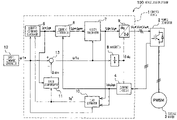
- FIG. 1 schematically shows the overall constitution of a motor driving system (an AC motor driving system) as a first embodiment of this invention.
- the AC motor driving system 100 comprises an electric motor 3 , a control device 1 for controlling the drive of the electric motor 3 and a power converter 2 for driving the electric motor 3 .
- the estimation of the angular position of the rotor in the electric motor 3 and the control of the rotational speed of the rotor are performed within the control device 1 .
- the electric motor 3 is assumed to be a three-phase synchronous motor having a permanent magnet rotor (hereafter referred to as PMSM if necessary).
- PMSM permanent magnet rotor
- the control device 1 performs a vector control in the dc-qc coordinate plane having its dc- and qc-axes, the dc-axis running along the direction of the exciting current (axis of the magnetic flux) and the qc-axis running along the direction of the torque current.
- the functions of the respective constituents of the control device 1 are realized by the program executed by hardware such as central processing units (CPUs) and memories, or a computer.
- the rotational coordinate system i.e. dc-qc plane
- the field windings consists of the U-phase, V-phase and W-phase field coils 62 , 63 and 64 in Y-connection.
- the electric motor 3 is so constructed that the rotor 61 having plural (two) magnetic poles rotates in the stator having the U-, V- and W-phase field coils 62 , 63 and 64 .
- the axis passing through the N and S magnetic poles of the rotor 61 be the effective axis, i.e.
- the control device 1 comprises a current detector 4 for detecting current flowing from a power converter 2 to the electric motor 3 ; a current command generator 5 for generating a target current flowing through the electric motor 3 ; a current controller 6 for operating in such a manner that the current having passed actually through the electric motor is made a new target current on the basis of the target current and the currents detected by the current detector 4 ; a vector calculator 7 for calculating a voltage to be applied to the electric motor 3 on the basis of a required speed command or a required command torque; an integrator 8 for integrating an electric angular speed ⁇ 1 c representative of the electric angular speed of the electric motor 3 estimated within the control device 1 and for calculating the electric angular position (or phase) ⁇ dc of the rotor of the electric motor 3 ; a d-q reverse transformer 9 for transforming the command voltages V d * and V q * along the dc- and qc-axes into the three-phase AC command voltages
- the control device 1 operates as follows.
- the current detector 4 detects the current flowing into the electric motor 3 to generate the detected current values I dc and I qc transformed into the dc- and qc-axes components.
- the current command generator 5 generates the current commands I d * and I q * along the dc- and qc-axes serving as target currents required to obtain a required speed or torque.
- the current controller 6 generates the second current commands I d ** and I q ** on the basis of the current commands I d * and I q * and the detected currents I dc and I qc .
- the vector calculator 7 delivers the command voltages V d * and V q * along the dc- and qc-axes which are to be applied to the electric motor 3 in such a manner that the detected currents I dc and I qc may be made equal to the current commands I d * and I q * depending on the second current commands I d ** and I q **, respectively.
- the d-q reverse transformer 9 calculates from the command voltages V d * and V q * the three-phase AC command voltages V U *, V V * and V W *, which are delivered to the power converter 2 .
- the power converter 2 applies the voltages corresponding to the command voltages V d * and V q * to the electric motor 3 on the basis of three-phase AC command voltages V U *, V V * and V W *.
- the magnetic pole position detector When the electric angular position ⁇ dc of the rotor of the electric motor 3 is directly detected by using a magnetic pole position detector, the magnetic pole position detector, depending on its position of detection, derives the d-axis current I d as the exciting current component and the q-axis current I q as the torque current component, from the detected current.
- the vector calculator 7 controls these two current components separately and changes the values of the voltage commands V d * and V q * along the dc- and qc-axes in such a manner that the current commands I d * and I q * are made equal to the detected currents I dc and I qc , respectively.
- the vector control it is necessary to detect the positions of the magnetic poles of the rotor in the electric motor. According to the electric motor drive system as the first embodiment of this invention as described above, however, the vector control can be easily carried out without using any magnetic pole position detector.
- the load estimator 10 consists of a load power calculator 101 for calculating the load power P ow on the basis of the voltage commands V d * and V q * and the detected currents I dc and I qc and a load current calculator 102 for obtaining the estimated torque current I q ⁇ to flow through the electric motor 3 on the basis of the load power P ow and the speed command ⁇ 1 *.
- the quantity with a circumflex ( ⁇ ) attached as a superscript indicates an estimated quantity.
- the load power P ow is calculated in the load power calculator 101 by using the following formula (1) while the estimated torque current I q ⁇ is obtained in the load current calculator 102 by using the following formula (2). It is to be noted here that these quantities are independent of the rotational speed of the electric motor 3 .
- P ow 1.5 ⁇ ( V d * ⁇ I dc +V q * ⁇ I qc ) ⁇ R 1 ⁇ ( I dc 2 +I qc 2 ) ⁇ (1)
- I q ⁇ P ow /( ⁇ 1 * ⁇ Ke ), (2)
- R 1 gives the winding resistance of the electric motor 3
- Ke indicates the constant associated with the induced voltage corresponding to the magnetic flux.
- the formula (1) gives the effective power supplied to the electric motor 3 minus the power loss across the winding resistance.
- the formula (1) is characterized in that it can complete its calculation without using the data relating to the positions of the magnetic poles as both the voltage commands V d * and V q * and the detected currents I dc and I qc are the quantities represented along the dc- and qc-axes.
- the formula (2) teaches that the product of torque and speed equals the power.
- the load estimator 10 calculates the estimated torque current I q ⁇ by using the formula (2) as the effective electric angular speed ⁇ 1 M equals the speed command ⁇ 1 * under the normal condition. It should be noted here that if the effect of salient poles is taken into consideration, the following formula (3) should be used to calculate the estimated torque current I q ⁇ .
- I q ⁇ P ow /[ ⁇ 1 * ⁇ Ke +( Ld ⁇ Lq ) ⁇ I d * ⁇ ], (3) where Ld indicates the inductance of the winding along the d-axis representing the magnetic flux axis of the electric motor 3 , and Lq gives the inductance of the winding along the q-axis representing the torque axis of the electric motor 3 .
- FIG. 4 schematically shows the constitution of the speed compensator 11 .
- a second adder 111 subtracts the torque current command I q * from the estimated torque current I q ⁇ to extract the oscillating component of the estimated current I q ⁇ , and a gain compensator 112 multiplies the oscillating component by a preset gain to produce the compensatory speed command ⁇ ⁇ c .
- FIG. 5 schematically shows the constitution of the current command generator 5 comprising an I q * generator 51 for generating current command I q * and an I d * generator 52 for generating the current command I d *.
- the I q * generator 51 consists of a selector 511 and a low-pass filter 512 .
- the I q * generator 51 holds therein the initial value I q 0 * of the current command I q * while the I d * generator 52 holds therein the initial value I d 0 * of the current command I d *.
- FIG. 6 (a) through (f) graphically show the operations of the current command generator 5 and the load estimator 10 when the load torque of the electric motor 3 linearly increases with the speed command ⁇ 1 * kept constant.
- (a) shows the speed command ⁇ 1 * which is kept constant.
- the load torque TL as shown in (b) of FIG. 6 increases linearly from the time instant t 1 to the time instant t 2 .
- the torque TM generated by the electric motor 3 is assumed to be equal to the load torque TL. Under this assumption, the load power P ow as shown in (c) of FIG. 6 varies in proportion to the load torque TL.
- the estimated current I q ⁇ which is obtained by the load estimator 10 , also varies in proportion to the load torque TL as shown in (d) of FIG. 6 .
- the selector 511 in the current command generator 5 continuously delivers the estimated current I q ⁇ so that, as shown in (e) of FIG. 6 , the current commands I q * becomes equal to the value which is obtained by filtering the estimated current I q ⁇ with the low-pass filter 512 .
- the current command I d * delivered from the I d * generator 52 as shown in (f) of FIG. 6 , gradually decreases starting at its initial value I d 0 * as the current command I d * increases.
- the I d * generator 52 determines the current command I d * on the basis of the absolute value abs(I q *) of the current command I q *.
- I d * max is the maximum value at which the current command I d * can be set
- I d * min is the minimum value at which the current command I d * can be set.
- the value of I d * max must be smaller than the value of the maximum current that the power converter 2 can generate.
- the value of I d * max can be set between the values corresponding respectively to the 100% and 150%, of the rated current of the electric motor 3 .
- the value of I d * min may ideally be equal to zero, but in such a case the motor synchronization will be easily lost when the load torque TL increases steeply from at a nearly zero value. Therefore, in order to prevent such synchronization loss, the value of I d * min should preferably be set between the values corresponding respectively to the 50% and 100%, of the rated current of the electric motor 3 . And the current command I d * can be determined by using the following formulas (4-1) through (4-3).
- Id* Id 0* (if ⁇ square root over (( Id *max) 2 ⁇ ( Iq *) 2 ) ⁇ square root over (( Id *max) 2 ⁇ ( Iq *) 2 ) ⁇ ⁇ Id 0*) (4-1)
- Id * ⁇ square root over (( Id *max) 2 ⁇ ( Iq *) 2 ) ⁇ square root over (( Id *max) 2 ⁇ ( Iq *) 2 ) ⁇ (if Id *min ⁇ square root over (( Id *max) 2 ⁇ ( Id *) 2 )) ⁇ square root over (( Id *max) 2 ⁇ ( Id *) 2 )) ⁇ Id *max) (4-2)
- Id* Id *min (if ⁇ square root over (( Id *max)2 ⁇ ( Iq *2)) ⁇ square root over (( Id *max)2 ⁇ ( Iq *2)) ⁇ Id *min) (4-3)
- the magnitude of the current along the q-axis can be varied depending on the value of the load torque so that it becomes possible to drive the electric motor 3 in such a manner that the motor loss may be decreased when the load is small.
- FIG. 8 (a) through (g) graphically show the changes in the speed command ⁇ 1 * and the load torque TL when the load torque TL changes stepwise with the speed command ⁇ 1 * kept constant; and the operations of the current command generator 5 , the load estimator 10 and the speed compensator 11 .
- the effective electric angular speed ⁇ 1 M and the generated torque TM, of the electric motor 3 oscillate as shown in (a) and (b) of FIG. 8 . If the oscillation of the effective electric angular speed ⁇ 1 M is large, the synchronization loss occurs, and the electric motor 3 can be driven no longer.
- the estimated electric angular speed ⁇ 1 c within the control device 1 can be obtained by subtracting in the adder 13 the compensatory speed command ⁇ ⁇ c generated by speed compensator 11 from the speed command ⁇ 1 *.
- the speed compensator 11 by using the speed compensator 11 , the operation of the control device 1 , when the load torque TL changes stepwise, is as shown in (a) to (g) of FIG. 9 . Namely, the oscillation of the effective electric angular speed ⁇ 1 M of the electric motor 3 can be suppressed even when the load torque TL changes stepwise so that the electric motor 3 can be stably driven.
- FIG. 10 (a) through (f) graphically show the operations of the current command generator 5 and the load estimator 10 .
- (a) shows the change with time of the speed command ⁇ 1 * for the electric motor 3 which is started at its resting state at the time instant t 1 and accelerated at a constant acceleration till the time instant t 2 .
- (b) shows a case where the load torque TL-is kept constant for simplicity. In this case, the actual value of the load power P ow bears an error with respect to the ideal value P ow — id, as shown in (c) of FIG.
- the estimated current I q ⁇ is infinite as the speed command ⁇ 1 * is zero while the electric motor 3 is at rest. Moreover, while the speed command ⁇ 1 * is small immediately after the start of the electric motor 3 , the estimated current I q ⁇ takes a very large value irrespective of its ideal value I q ⁇ _id so that it is possible that the electric motor 3 cannot be normally driven.
- the selector 511 in the current command generator 5 is actuated by the speed command ⁇ 1 *.
- the selector 511 operates in such a manner that the initial value I q 0 * of the current command I q * is delivered while the electric motor 3 is at rest and while the absolute value of the speed command ⁇ 1 * remains smaller than the threshold ⁇ 10 * of the speed command ⁇ 1 *, whereas the estimated current I q ⁇ is delivered at and after the time instant t 3 when the absolute value exceeds the threshold ⁇ 10 *. Accordingly, the obtained current command I q * changes as shown in (e) of FIG.
- the current command I q * can be prevented from becoming very large irrespective of the load condition while the absolute value of the speed command ⁇ 1 * is small immediately after the start of the electric motor 3 , so that the electric motor 3 can be started when it is at rest.
- the threshold ⁇ 10 * of the speed command ⁇ 1 * depends on the accuracy in setting the ratings of the electric motor 3 used in the control device 1 . For example, let it be assumed that the voltage drop across the resistor is 5% of the induced voltage and that the error in setting the resistance of the resistor is 10% of the induced voltage. Then, the speed command ⁇ 1 * becomes 2% of the rated speed and the error in the estimated current I q ⁇ becomes 25% of the current command I q * at the rated load. Consequently, a fair operation can be obtained if the speed command threshold ⁇ 10 * is set not less than 2% of the rated angular speed of the electric motor 3 .
- the initial value I q 0 * of the current command I q * is set to zero.
- the initial value I q 0 * can be set at an arbitrary value which satisfies the following inequality (5) or it may be varied depending on the speed command ⁇ 1 *. ( I d 0*) 2 +( I q 0*) 2 ⁇ ( I d * max ) 2 (5)
- the current through the electric motor 3 can be changed depending on the load condition so that the electric motor 3 can be stably driven even if the load changes.
- an apparatus and a system for driving an AC motor wherein the electric motor 3 can be stably driven depending on the mechanical load thereon as the load power P ow is estimated by the load estimator 10 on the basis of the voltage commands V d * and V q * and the detected currents I dc and I qc . Further, the electric motor 3 can be effectively driven even when it is running at a low speed.
- FIG. 11 schematically shows the overall constitution of an AC motor driving system as the second embodiment of this invention.
- An axial displacement estimator 14 estimates the positions of the magnetic poles by obtaining the axial displacement ⁇ defined in FIG. 2 and representing the displacement of the dc-axis with respect to the d-axis.
- the current as commanded flows along the effective axis and therefore the current component associated with the generation of torque does not decrease.
- the estimated axial displacement ⁇ c is calculated according to the following formula (6).
- ⁇ c tan - 1 ⁇ ( Vd * - R ⁇ ⁇ 1 ⁇ Idc + ⁇ ⁇ ⁇ 1 ⁇ ⁇ c ⁇ Iqc Vq * - R ⁇ ⁇ 1 ⁇ Iqc - ⁇ ⁇ ⁇ 1 ⁇ ⁇ c ⁇ Lq ⁇ Idc ) ( 6 )
- a PLL operational unit 15 is a PI controller which implements position-sensor-free vector controls, the PLL operational unit 15 receiving the estimated axial displacement ⁇ c as an input and delivering the second compensatory speed command ⁇ ⁇ cp as an output.
- FIG. 12 schematically shows the constitution of the current command generator 5 used in this embodiment.
- An I q * generator 51 b includes a selector 511 b for selecting one of the initial value I q 0 * of the current command I q *, the estimated current command I q ⁇ and the detected current I qc along the qc-axis.
- a second selector 53 selects between the output of an I d * generator 52 and the current command value I d1 * along the dc-axis during the position-sensor-free vector controls.
- a second low-pass filter (LPF) 54 serves to prevent the delivered current command I d * from changing stepwise in response to the input transience between the output of the I d * generator 52 and the current command value I d1 *.
- the load estimator 10 b used in this embodiment may be a calculator which calculates the estimated current command I q ⁇ by using the following formula (7).
- the adder 13 b subtracts the compensatory speed command ⁇ ⁇ c and the second compensatory speed command ⁇ ⁇ cp delivered as output of the PLL controller 15 , from the speed command ⁇ 1 * so as to deliver an output as estimated electric angular speed ⁇ 1 c .
- the other components of this embodiment are the same as those used in the first embodiment of this invention.
- FIG. 13 (a) through (f) graphically show the operations of the axial displacement calculator 14 , the current command generator 5 b and the load estimator 10 all as shown in FIG. 11 , wherein the load torque TL on the electric motor 3 increases linearly with the speed command ⁇ 1 * kept constant.
- FIG. 13 (a) shows the constant speed command ⁇ 1 *.
- the load torque TL increases linearly from the time instant t 1 through the time instant t 2 , the torque TM generated by the electric motor 3 being assumed to be nearly equal to the load torque TL.
- the estimated axial displacement ⁇ c varies non-linearly as shown in (c) of FIG. 13 , but the estimated current command I q ⁇ varies in proportion to the load torque TL according to the formula (7) as shown in (d) of FIG. 13 . If the selector 511 b delivers the estimated current command I q ⁇ continuously, the operation of the current command generator 5 b is similar to that of the current command generator 5 as shown in FIG. 5 .
- the selector 511 b and the second selector 53 are to be changed over as indicated in the following table 1.
- (c) shows the axial displacement ⁇ and its estimated version ⁇ c .
- the axial displacement ⁇ takes up a value corresponding to the load torque TL.
- ⁇ c will have an error with respect to ⁇ .
- the error will be greater as the effective electric angular speed ⁇ 1 M decreases.
- the estimated torque current I q ⁇ shown in (c) of FIG. 14 will also have an error with respect to its ideal value I q ⁇ _id.
- a speed command threshold ⁇ 10 * is introduced and thus the current command I q * is prevented from taking up a value deviated largely from the ideal value I q ⁇ _id by operating the selector 511 b in such a manner that it delivers the initial value I q 0 * while the absolute value of the speed command ⁇ 1 * remains smaller than the threshold ⁇ 10 * whereas it changes its output to the estimated torque current I q ⁇ when the absolute value exceeds the threshold ⁇ 10 * at the time instant t 2 .
- the selector 511 b delivers the detected current I qc
- the second selector 53 delivers the current command value I d1 *
- the PLL controller 15 starts its operation so that the operation of the control device 1 is changed over to the position-sensor-free vector control. Consequently, the current commands I d * and I q * vary as shown in (e) and (f) of FIG. 14 , respectively.
- the current command I q * takes up a value corresponding to the load torque TL at the time instant t 3 and since the axial displacement ⁇ and its estimated version ⁇ c are both nearly equal to zero, the switch-over of the control to the position-sensor-free vector control can be smoothly performed.
- a power converter 2 comprises a main circuit 21 , a DC power source 22 , a (non-inductive) resistor 23 , and a phase current detector 24 for detecting the respective phase currents I U , I V and I W , which are supplied to a current detector 4 .
- the current detector 4 is a d-q transformer which can derive the detected currents I dc and I qc along the dc- and qc-axes from the detected phase currents I U , I V and I W .
- the phase current detector 24 has only to detect at least two phase currents for the purpose.
- FIG. 16 shows the constitution implementing another method for current detection.
- a power converter 2 ′ includes the main circuit 21 , the DC power source 22 , the (non-inductive) resistor 23 , these being the same as those shown in FIG. 15 , and a direct current detector 25 for detecting the direct current I sh flowing from the DC power source 22 to the main circuit 21 on the basis of the voltage developed across the resistor 23 .
- the direct current I sh is then supplied to a current detector 4 ′ which consists of the d-q transformer 41 shown in FIG. 15 and a motor current estimator 42 for deriving the phase currents I U , I V and I W from the direct current I sh .
- the operation of the motor current estimator 42 does not feature this embodiment and it is well known to those skilled in the art, and therefore its description will be omitted.
- this embodiment aims at estimating the load on the electric motor within the control device for controlling the electric motor and at controlling the electric motor in accordance with the load.
- the estimation of the load according to this embodiment is performed by calculating the power to be supplied to the electric motor on the basis of the voltage commands developed along the dc- and qc-axes and the detected currents and by estimating the torque current on the basis of the calculated power.
- the current commands are determined as the current command values represented along the dc- and qc-axes on the basis of the estimated torque current, and the electric motor is driven on the basis of the voltage commands along the dc- and qc-axes derived from the current command values.
- the oscillating component of the load on the electric motor is extracted on the basis of the estimated torque current and the current command values developed along the dc- and qc-axes, and the speed command processed within the control device is compensated depending on this oscillating component.
- the load may also be estimated by obtaining the axial error representing the axial displacement of the dc-axis with respect to the d-axis by using the detected currents and the voltage commands developed along the dc- and qc-axes and by estimating the torque current on the basis of the axial displacement.
- the torque current corresponding to the load on the electric motor is estimated on the basis of the detected currents and the voltage command values developed along the dc- and qc-axes within the control device, the current commands and the speed command are controlled depending on the estimated torque current, and therefore the electric motor can be stably driven depending on the load imposed thereon.
- the control wherein the load power P ow is estimated by using the load estimator 10 can be smoothly switched to the control wherein the axial error is used. Accordingly, the electric motor can be drive by using the axial displacement in the speed range within which the position-sensor-free vector control is applicable. Thus, a more preferable control can be achieved.
Landscapes
- Engineering & Computer Science (AREA)
- Power Engineering (AREA)
- Control Of Ac Motors In General (AREA)
- Control Of Electric Motors In General (AREA)
Abstract
Description
θdc=θd+Δθ,
where the d-axis and the axis of the
P ow=1.5×{(V d *×I dc +V q *×I qc)−R1×(I dc 2 +I qc 2)} (1)
I q ^=P ow/(ω1*×Ke), (2)
I q ^=P ow/[ω1*×{Ke+(Ld−Lq)×I d*}], (3)
where Ld indicates the inductance of the winding along the d-axis representing the magnetic flux axis of the
Id*=Id0* (if √{square root over ((Id*max)2−(Iq*)2)}{square root over ((Id*max)2−(Iq*)2)}<Id0*) (4-1)
Id*=√{square root over ((Id*max)2−(Iq*)2)}{square root over ((Id*max)2−(Iq*)2)} (if Id*min<√{square root over ((Id*max)2−(Id*)2))}{square root over ((Id*max)2−(Id*)2))}≦Id*max) (4-2)
Id*=Id*min (if √{square root over ((Id*max)2−(Iq*2))}{square root over ((Id*max)2−(Iq*2))}≦Id*min) (4-3)
(I d0*)2+(I q0*)2≦(I d*max)2 (5)
I q ^=I dc×sin(Δθc)+I qc×cos(Δθc) (7)
Also, the
| TABLE 1 | ||
| Speed command ω1* | ||
| ω10* ≦ | ||||
| abs(ω1*) < ω10* | abs(ω1*) < ω11* | ω11* ≦ abs(ω1*) | ||
| Output of | Iq0* | Iq | Iqc |
| | |||
| Output of 2nd | Output of Id* | Output of Id* | Id1* |
| | gnrtr. | gnrtr. | |
The operations of the
Claims (5)
Applications Claiming Priority (2)
| Application Number | Priority Date | Filing Date | Title |
|---|---|---|---|
| JP2006-003570 | 2006-01-11 | ||
| JP2006003570A JP4989075B2 (en) | 2006-01-11 | 2006-01-11 | Electric motor drive control device and electric motor drive system |
Publications (2)
| Publication Number | Publication Date |
|---|---|
| US20070159130A1 US20070159130A1 (en) | 2007-07-12 |
| US7602138B2 true US7602138B2 (en) | 2009-10-13 |
Family
ID=38006589
Family Applications (1)
| Application Number | Title | Priority Date | Filing Date |
|---|---|---|---|
| US11/527,475 Active US7602138B2 (en) | 2006-01-11 | 2006-09-27 | Driving apparatus and driving system for electric motor |
Country Status (4)
| Country | Link |
|---|---|
| US (1) | US7602138B2 (en) |
| EP (1) | EP1808956B1 (en) |
| JP (1) | JP4989075B2 (en) |
| CN (1) | CN101001068B (en) |
Cited By (3)
| Publication number | Priority date | Publication date | Assignee | Title |
|---|---|---|---|---|
| US20130093367A1 (en) * | 2011-10-14 | 2013-04-18 | Robert Bosch Gmbh | Method and device for actuating an electric machine in the motor starting mode |
| US10992243B2 (en) * | 2017-09-22 | 2021-04-27 | Nidec Motor Corporation | System and computer-implemented method for reducing angle error in electric motors |
| US12510091B2 (en) * | 2023-08-21 | 2025-12-30 | Richtek Technology Corp. | Method and system for failure predication of cooling fan |
Families Citing this family (20)
| Publication number | Priority date | Publication date | Assignee | Title |
|---|---|---|---|---|
| US7733047B2 (en) * | 2006-02-08 | 2010-06-08 | Mitsubishi Electric Corporation | Motor controller and motor control method |
| JP4928850B2 (en) * | 2006-06-28 | 2012-05-09 | 株式会社東芝 | Rotating machine control device |
| JP2008067556A (en) * | 2006-09-11 | 2008-03-21 | Sanyo Electric Co Ltd | Motor controller |
| JP5033662B2 (en) * | 2008-01-31 | 2012-09-26 | 株式会社日立製作所 | Electric motor drive system |
| JP2009247181A (en) * | 2008-03-31 | 2009-10-22 | Jtekt Corp | Motor control device and electric power steering device |
| JP2010057228A (en) * | 2008-08-27 | 2010-03-11 | Hitachi Ltd | Motor control device |
| JP4607215B2 (en) * | 2008-09-22 | 2011-01-05 | 東芝エレベータ株式会社 | Elevator control device |
| JP2010206874A (en) * | 2009-02-27 | 2010-09-16 | Hitachi Appliances Inc | Freezing device |
| EP2269495A1 (en) * | 2009-06-30 | 2011-01-05 | Braun GmbH | Method for operating a domestic appliance and domestic appliance |
| JP5309242B1 (en) * | 2012-04-13 | 2013-10-09 | ファナック株式会社 | Synchronous motor control device for controlling a synchronous motor to stop the synchronous motor during power regeneration and power failure |
| JP2014180148A (en) * | 2013-03-15 | 2014-09-25 | Hitachi Appliances Inc | Motor controller |
| KR20170034552A (en) * | 2015-09-21 | 2017-03-29 | 주식회사 브이씨텍 | Speed control apparatus for electric vehicle |
| DE102016015237B4 (en) * | 2016-12-21 | 2019-02-21 | Kuka Roboter Gmbh | Safe determination of axis positions and / or velocities of a robot |
| JP7052255B2 (en) * | 2017-08-25 | 2022-04-12 | コニカミノルタ株式会社 | Image forming device |
| JP7093071B2 (en) * | 2017-12-27 | 2022-06-29 | 青島海爾洗衣机有限公司 | washing machine |
| US11817811B2 (en) * | 2019-03-12 | 2023-11-14 | Allegro Microsystems, Llc | Motor controller with power feedback loop |
| CN111756303B (en) * | 2019-03-29 | 2022-06-17 | 安川电机(中国)有限公司 | Frequency converter and control method of output voltage thereof, and control method of vacuum system |
| US12126287B2 (en) * | 2020-02-26 | 2024-10-22 | Fanuc Corporation | Magnetic pole position detection device |
| JP7678687B2 (en) * | 2021-03-26 | 2025-05-16 | キヤノン株式会社 | Motor control device and image forming apparatus |
| JP7714991B2 (en) * | 2021-09-30 | 2025-07-30 | 株式会社富士通ゼネラル | Motor control device |
Citations (20)
| Publication number | Priority date | Publication date | Assignee | Title |
|---|---|---|---|---|
| JPH07245981A (en) | 1994-03-01 | 1995-09-19 | Fuji Electric Co Ltd | Magnetic pole position detector for electric motor |
| US5923728A (en) * | 1997-05-09 | 1999-07-13 | Matsushita Electric Industrial Co., Ltd. | Motor controller |
| US5936378A (en) * | 1997-03-27 | 1999-08-10 | Matsushita Electric Industrial Co., Ltd. | Motor controller |
| US6018694A (en) * | 1996-07-30 | 2000-01-25 | Denso Corporation | Controller for hybrid vehicle |
| JP2001251889A (en) | 2000-03-06 | 2001-09-14 | Hitachi Ltd | Method for estimating rotor position of synchronous motor, control method without position sensor, and control device |
| US6400107B1 (en) * | 1999-08-04 | 2002-06-04 | Sharp Kabushiki Kaisha | Motor control device capable of driving a synchronous motor with high efficiency and high reliability |
| JP2002233199A (en) | 2001-02-05 | 2002-08-16 | Railway Technical Res Inst | Control device for permanent magnet synchronous motor |
| US20020153857A1 (en) * | 2001-03-08 | 2002-10-24 | Hitachi, Ltd. | Driving device for synchronous motor |
| EP1263125A2 (en) | 2001-05-31 | 2002-12-04 | Toyota Jidosha Kabushiki Kaisha | Drive control apparatus and method of alternating current motor |
| US20030030404A1 (en) | 2001-06-06 | 2003-02-13 | Hitachi, Ltd. | Sensorless control system for synchronous motor |
| US20030052640A1 (en) * | 2001-08-09 | 2003-03-20 | Yoshitaka Iwaji | Synchronous motor driving system |
| US6696812B2 (en) * | 2001-04-11 | 2004-02-24 | Hitachi, Ltd. | Control apparatus for electric motor |
| US6727669B2 (en) * | 2001-09-18 | 2004-04-27 | Toyoda Koki Kabushiki Kaisha | Motor-driven power steering apparatus |
| JP2004222382A (en) | 2003-01-14 | 2004-08-05 | Mitsubishi Heavy Ind Ltd | Apparatus and method for controlling operation of motor |
| US6803736B1 (en) * | 1999-05-19 | 2004-10-12 | Robert Bosch Gmbh | Control system which carries out the model-supported safety monitoring of an electronically regulated controller in the motor vehicle |
| US6822417B2 (en) * | 2002-03-22 | 2004-11-23 | Matsushita Electric Industrial Co., Ltd. | Synchronous reluctance motor control device |
| US20050063117A1 (en) * | 2002-12-06 | 2005-03-24 | Hitachi, Ltd. | Power supply system |
| US7075259B2 (en) * | 2004-01-09 | 2006-07-11 | Denso Corporation | Motor control apparatus for adjusting target rotation speed of motor in accordance with current condition of motor load |
| US7170243B2 (en) * | 2005-05-18 | 2007-01-30 | Mitsubishi Denki Kabushiki Kaishia | Drive method for brushless motor and drive control apparatus therefor |
| US7235937B2 (en) * | 2004-09-21 | 2007-06-26 | Denso Corporation | Traction motor control system |
Family Cites Families (4)
| Publication number | Priority date | Publication date | Assignee | Title |
|---|---|---|---|---|
| JPS59194689A (en) * | 1983-04-20 | 1984-11-05 | Fuji Electric Co Ltd | Speed control system of ac motor |
| JP2001136775A (en) * | 1999-11-04 | 2001-05-18 | Yaskawa Electric Corp | Load estimation method for permanent magnet rotor type synchronous motor and control device for permanent magnet rotor type synchronous motor |
| JP4440441B2 (en) * | 2000-08-11 | 2010-03-24 | 本田技研工業株式会社 | Motor control device |
| JP3972124B2 (en) * | 2002-07-10 | 2007-09-05 | 株式会社日立製作所 | Synchronous motor speed control device |
-
2006
- 2006-01-11 JP JP2006003570A patent/JP4989075B2/en not_active Expired - Fee Related
- 2006-09-25 CN CN2006101592562A patent/CN101001068B/en not_active Expired - Fee Related
- 2006-09-27 US US11/527,475 patent/US7602138B2/en active Active
- 2006-09-29 EP EP06020593.7A patent/EP1808956B1/en not_active Ceased
Patent Citations (22)
| Publication number | Priority date | Publication date | Assignee | Title |
|---|---|---|---|---|
| JPH07245981A (en) | 1994-03-01 | 1995-09-19 | Fuji Electric Co Ltd | Magnetic pole position detector for electric motor |
| US6018694A (en) * | 1996-07-30 | 2000-01-25 | Denso Corporation | Controller for hybrid vehicle |
| US5936378A (en) * | 1997-03-27 | 1999-08-10 | Matsushita Electric Industrial Co., Ltd. | Motor controller |
| US5923728A (en) * | 1997-05-09 | 1999-07-13 | Matsushita Electric Industrial Co., Ltd. | Motor controller |
| US6803736B1 (en) * | 1999-05-19 | 2004-10-12 | Robert Bosch Gmbh | Control system which carries out the model-supported safety monitoring of an electronically regulated controller in the motor vehicle |
| US6400107B1 (en) * | 1999-08-04 | 2002-06-04 | Sharp Kabushiki Kaisha | Motor control device capable of driving a synchronous motor with high efficiency and high reliability |
| JP2001251889A (en) | 2000-03-06 | 2001-09-14 | Hitachi Ltd | Method for estimating rotor position of synchronous motor, control method without position sensor, and control device |
| JP2002233199A (en) | 2001-02-05 | 2002-08-16 | Railway Technical Res Inst | Control device for permanent magnet synchronous motor |
| US20020153857A1 (en) * | 2001-03-08 | 2002-10-24 | Hitachi, Ltd. | Driving device for synchronous motor |
| US6696812B2 (en) * | 2001-04-11 | 2004-02-24 | Hitachi, Ltd. | Control apparatus for electric motor |
| EP1263125A2 (en) | 2001-05-31 | 2002-12-04 | Toyota Jidosha Kabushiki Kaisha | Drive control apparatus and method of alternating current motor |
| US20030030404A1 (en) | 2001-06-06 | 2003-02-13 | Hitachi, Ltd. | Sensorless control system for synchronous motor |
| US20030052640A1 (en) * | 2001-08-09 | 2003-03-20 | Yoshitaka Iwaji | Synchronous motor driving system |
| US6628099B2 (en) * | 2001-08-09 | 2003-09-30 | Hitachi, Ltd. | Synchronous motor driving system and sensorless control method for a synchronous motor |
| US20030057912A1 (en) * | 2001-08-09 | 2003-03-27 | Yoshitaka Iwaji | Synchronous motor driving system and sensorless control method for a synchronous motor |
| US6727669B2 (en) * | 2001-09-18 | 2004-04-27 | Toyoda Koki Kabushiki Kaisha | Motor-driven power steering apparatus |
| US6822417B2 (en) * | 2002-03-22 | 2004-11-23 | Matsushita Electric Industrial Co., Ltd. | Synchronous reluctance motor control device |
| US20050063117A1 (en) * | 2002-12-06 | 2005-03-24 | Hitachi, Ltd. | Power supply system |
| JP2004222382A (en) | 2003-01-14 | 2004-08-05 | Mitsubishi Heavy Ind Ltd | Apparatus and method for controlling operation of motor |
| US7075259B2 (en) * | 2004-01-09 | 2006-07-11 | Denso Corporation | Motor control apparatus for adjusting target rotation speed of motor in accordance with current condition of motor load |
| US7235937B2 (en) * | 2004-09-21 | 2007-06-26 | Denso Corporation | Traction motor control system |
| US7170243B2 (en) * | 2005-05-18 | 2007-01-30 | Mitsubishi Denki Kabushiki Kaishia | Drive method for brushless motor and drive control apparatus therefor |
Cited By (4)
| Publication number | Priority date | Publication date | Assignee | Title |
|---|---|---|---|---|
| US20130093367A1 (en) * | 2011-10-14 | 2013-04-18 | Robert Bosch Gmbh | Method and device for actuating an electric machine in the motor starting mode |
| US9233624B2 (en) * | 2011-10-14 | 2016-01-12 | Robert Bosch Gmbh | Method and device for actuating an electric machine in the motor starting mode |
| US10992243B2 (en) * | 2017-09-22 | 2021-04-27 | Nidec Motor Corporation | System and computer-implemented method for reducing angle error in electric motors |
| US12510091B2 (en) * | 2023-08-21 | 2025-12-30 | Richtek Technology Corp. | Method and system for failure predication of cooling fan |
Also Published As
| Publication number | Publication date |
|---|---|
| JP4989075B2 (en) | 2012-08-01 |
| EP1808956A2 (en) | 2007-07-18 |
| US20070159130A1 (en) | 2007-07-12 |
| JP2007189766A (en) | 2007-07-26 |
| EP1808956B1 (en) | 2013-12-25 |
| CN101001068B (en) | 2011-01-05 |
| EP1808956A3 (en) | 2009-07-29 |
| CN101001068A (en) | 2007-07-18 |
Similar Documents
| Publication | Publication Date | Title |
|---|---|---|
| US7602138B2 (en) | Driving apparatus and driving system for electric motor | |
| KR100455630B1 (en) | Sensorless control method and apparatus of permanent magnet synchronous motor | |
| JP3719910B2 (en) | Motor control device | |
| JP3860031B2 (en) | Synchronous motor control device and control method of synchronous motor | |
| JP5130031B2 (en) | Position sensorless control device for permanent magnet motor | |
| US8988027B2 (en) | Motor control apparatus and motor control method | |
| EP1998435B1 (en) | Method and system for estimating rotor angular position and rotor angular velocity at low speeds or standstill | |
| JP6367332B2 (en) | Inverter control device and motor drive system | |
| KR101376389B1 (en) | Flux controller for induction motor | |
| CN101542891B (en) | Sensorless Control of Synchronous Motors | |
| US20040104704A1 (en) | Motor control apparatus | |
| WO2008004417A1 (en) | Sensorless control apparatus of synchronous machine | |
| CN101449456A (en) | Motor drive and compressor drive | |
| JP2008017690A (en) | Motor speed estimation method and speed estimation apparatus | |
| WO2016121237A1 (en) | Inverter control device and motor drive system | |
| US7072790B2 (en) | Shaft sensorless angular position and velocity estimation for a dynamoelectric machine based on extended rotor flux | |
| JP3832443B2 (en) | AC motor control device | |
| JP4458794B2 (en) | Motor control device | |
| US11837982B2 (en) | Rotary machine control device | |
| JP5334524B2 (en) | Permanent magnet synchronous motor control device and control method thereof | |
| JP4583257B2 (en) | AC rotating machine control device | |
| JPH04364384A (en) | Resistance estimation starting system for induction motor | |
| JP2002281795A (en) | Controlling method for power refeeding to synchronous motor and controller for synchronous motor | |
| JP2005192295A (en) | Induction motor control device | |
| JP5228435B2 (en) | Inverter control device and control method thereof |
Legal Events
| Date | Code | Title | Description |
|---|---|---|---|
| AS | Assignment |
Owner name: HITACHI INDUSTRIAL EQUIPMENT SYSTEMS, CO., LTD., J Free format text: ASSIGNMENT OF ASSIGNORS INTEREST;ASSIGNORS:KANEKO, DAIGO;SUZUKI, TAKAHIRO;ENDO, TSUNEHIRO;AND OTHERS;REEL/FRAME:018656/0832;SIGNING DATES FROM 20061102 TO 20061110 |
|
| STCF | Information on status: patent grant |
Free format text: PATENTED CASE |
|
| FEPP | Fee payment procedure |
Free format text: PAYOR NUMBER ASSIGNED (ORIGINAL EVENT CODE: ASPN); ENTITY STATUS OF PATENT OWNER: LARGE ENTITY |
|
| FPAY | Fee payment |
Year of fee payment: 4 |
|
| FPAY | Fee payment |
Year of fee payment: 8 |
|
| MAFP | Maintenance fee payment |
Free format text: PAYMENT OF MAINTENANCE FEE, 12TH YEAR, LARGE ENTITY (ORIGINAL EVENT CODE: M1553); ENTITY STATUS OF PATENT OWNER: LARGE ENTITY Year of fee payment: 12 |