US7600236B2 - Disk-shaped storage medium loading/ejection mechanism, disk device, and disk autochanger - Google Patents
Disk-shaped storage medium loading/ejection mechanism, disk device, and disk autochanger Download PDFInfo
- Publication number
- US7600236B2 US7600236B2 US11/362,293 US36229306A US7600236B2 US 7600236 B2 US7600236 B2 US 7600236B2 US 36229306 A US36229306 A US 36229306A US 7600236 B2 US7600236 B2 US 7600236B2
- Authority
- US
- United States
- Prior art keywords
- loading
- disk
- ejection
- storage medium
- shaped storage
- Prior art date
- Legal status (The legal status is an assumption and is not a legal conclusion. Google has not performed a legal analysis and makes no representation as to the accuracy of the status listed.)
- Expired - Fee Related, expires
Links
Images


Classifications
-
- G—PHYSICS
- G11—INFORMATION STORAGE
- G11B—INFORMATION STORAGE BASED ON RELATIVE MOVEMENT BETWEEN RECORD CARRIER AND TRANSDUCER
- G11B17/00—Guiding record carriers not specifically of filamentary or web form, or of supports therefor
- G11B17/02—Details
- G11B17/04—Feeding or guiding single record carrier to or from transducer unit
- G11B17/05—Feeding or guiding single record carrier to or from transducer unit specially adapted for discs not contained within cartridges
- G11B17/051—Direct insertion, i.e. without external loading means
-
- G—PHYSICS
- G11—INFORMATION STORAGE
- G11B—INFORMATION STORAGE BASED ON RELATIVE MOVEMENT BETWEEN RECORD CARRIER AND TRANSDUCER
- G11B17/00—Guiding record carriers not specifically of filamentary or web form, or of supports therefor
- G11B17/02—Details
- G11B17/04—Feeding or guiding single record carrier to or from transducer unit
- G11B17/0401—Details
- G11B17/0402—Servo control
- G11B17/0404—Servo control with parallel drive rollers
Definitions
- the present invention relates to a mechanism for loading a disk-shaped storage medium into a housing through an opening and for ejecting the disk-shaped storage medium from that housing through that opening, that is, a loading/ejection mechanism, and a disk device and a disk autochanger having that loading/ejection mechanism.
- CDs and other disk-shaped storage media are usually loaded into a disk player of an audio system etc. to provide the user with music.
- the display player is a disk autochanger, it stores a plurality of disks in its housing and automatically selects one disk at a time in a preferred order so as to provide the user with music.
- the disk player etc. is defined in shape by its housing. It requires an opening for inserting and taking out disks to and from the housing and a disk loading/ejection mechanism provided near it.
- FIG. 14 is a view of an example of a general disk loading/ejection mechanism and a disk device provided with the same.
- the disk device 1 has a disk loading/ejection mechanism 2 for loading a disk D into the housing 4 (IN) or for ejecting it from the housing 4 (OUT).
- This disk loading/ejection mechanism is provided near an opening 3 formed at part of the housing 4 and is for example comprised of a loading/ejecting roller 2 a and a support plate 2 b paired with this.
- Each disk D loaded from the opening 3 by the disk loading/ejection mechanism 2 into the housing 4 is stored in a disk holding member 5 .
- a disk holding member 5 shows a disk device 1 constituted by a disk autochanger. There are six disk holding members 5 for hold six stacked disks in the illustration.
- a separating means (not shown) is inserted between the holding member 5 storing the selected disk D and an adjoining holding member 5 to push the two apart.
- a playback (recording) pickup is inserted between them for playing back or recording on the disk.
- FIG. 15 is a plan view showing the configuration of the main parts of FIG. 14 in a simplified manner.
- FIG. 15 the disk loading/ejection mechanism 2 , housing 4 , and disk holding members 5 shown in FIG. 14 are shown simply with the disk D being taken out. Note that to facilitate understanding, parts which are originally not visible are also all drawn by solid lines.
- the point of the disk loading/ejection mechanism 2 in the disk device 1 according to the present invention is that the loading/ejection direction of the disk D is not straight as shown by the arrow A in FIG. 15 , but is offset as shown by the arrow B of the figure.
- FIGS. 16A and 16B are a perspective view and plan view of the device disclosed in Japanese Patent Publication (A) No. 2001-76408.
- FIGS. 16A and 16B according to Japanese Patent Publication (A) No. 2001-76408, there is provided a data storage medium drive device where even if part of a small sized data storage medium happens to fall inside from the opening of a loading tray, it will not be caught up in the internal mechanism and can be reliably unloaded and ejected.
- the configuration and effects are as follows.
- a guide member 103 is formed at a position of an offset side 102 a of an opening 102 of a loading base 101 . Due to this, when moving in the unloading direction, even if a small sized optical disk D would be liable to fall into the space between a loading tray 104 and a receiving surface 105 of the loading base 101 from the offset side 102 a of the opening 102 , in the process of moving in the unloading direction, the falling side of the optical disk will run up against the guide member 103 and forcibly be moved toward the center, therefore the disk D will be able to be made to move in the ejection direction in a more horizontal state along the medium tray surface. Due to this, the disk D will not be caught up in the gears and other internal mechanisms of a gear unit 106 and will be able to be reliably ejected.
- Japanese Patent Publication (A) No. 2001-76408 discloses changing the direction of transport of the disk D from a straight direction near the opening 102 toward the center as shown by D′ at the time of ejection of the disk D.
- FIGS. 17A and 17B are views for explaining the problems to be solved by the invention.
- FIG. 17A corresponds to FIG. 15
- the disk device 1 for example, the disk autochanger, is comprised of a large number of complicated component parts,
- the housing 4 shown in FIGS. 16A and 16B while not shown, actually has these component parts fit inside it.
- This large number of component parts is arranged in spaces other than the locations of the disk holding members 5 , the disks D, and the playback (recording) pickup PU in FIG. 14 .
- the present assignee previously proposed the layout shown in FIG. 17B . That is, it proposed to shift the disk holding members 5 and the loading/ejection mechanism 2 from the center of the disk device 1 to either the left or right side (in the figure, the right side).
- the opening 3 through which the disk D is inserted and taken out is naturally shifted in position from the center to one side (right side). This first of all causes the problem of poor user friendliness and second causes the problem of an odd feeling in the design as viewed from the front of the disk device 1 .
- An object of the present invention is to provide a loading/ejection mechanism for a disk-shaped storage medium enabling various component parts to be laid out in a disk device 1 relatively freely by securing a large space at one side of the housing and enabling an opening 3 for inserting and taking out the disk at the center of the front of the housing as in the past.
- a loading/ejection mechanism for inserting and taking out a disk-shaped storage medium (disk D) through an opening, provided with an offset drive function unit ( 10 ) for shifting the loading/ejection direction when inserting and taking out the disk D to a loading/ejection direction (B) offset from the straight direction (A) perpendicularly intersecting the opening direction of the opening ( 3 ).
- FIG. 1 is a view of the basic configuration of a loading/ejection mechanism according to the present invention
- FIG. 2 is a view showing an example of a disk device provided with the loading/ejection mechanism according to the present invention as seen from the front;
- FIG. 3 is a plan view of a first embodiment of the present invention.
- FIGS. 4A and 4B are views of two loading/ejecting stages in FIG. 3 seen from the front;
- FIG. 5 is a detailed enlarged front view of an offset loading/ejecting drive part 11 and a holding part 15 ;
- FIG. 6A is a front view showing a pair of a holding roller and a left-right symmetrical drive roller, while FIG. 6B is a side view along the arrow b;
- FIGS. 7A and 7B are views for explaining the operation in the case of the configuration of FIGS. 6A and 6B ;
- FIG. 8 is a view of the path of disk loading/ejection
- FIGS. 9A , 9 B, and 9 C are sectional views showing three examples of the first embodiment of an inside abutting part 21 ;
- FIGS. 10A , 10 B, and 10 C are sectional views showing three examples of a second embodiment of an inside abutting part 21 ;
- FIG. 11A is a plan view of the second embodiment of the present invention, while FIG. 11B is a front sectional view of the same;
- FIG. 12A is a plan view of a modification of the second embodiment of the present invention, while FIG. 12B is a front sectional view of the same;
- FIGS. 13A , 13 B, 13 C, and 13 D are plan views for explaining a third embodiment of the present invention.
- FIG. 14 is a view of an example of a general disk loading/ejection mechanism and a disk device provided with the same;
- FIG. 15 is a simplified view of the configuration of principal parts of FIG. 14 ;
- FIGS. 16A and 16B are a perspective view and plan view of a device disclosed in Japanese Patent Publication (A) No. 2001-76408;
- FIGS. 17A and 17B are plan views for explaining the problem to be solved by the present invention.
- FIG. 18 is a plan view of a specific example of fitting the required component parts into the spaces shown in FIG. 1 .
- FIG. 1 is a plan view of the basic configuration of a loading/ejection mechanism according to the present invention.
- FIG. 2 is a view of an example of a disk device provided with the loading/ejection mechanism according to the present invention as seen from the front. As explained above, the opening 3 for inserting and taking out the disk D is shown arranged at the center of the front of the housing 4 as in the past.
- the loading/ejection mechanism shown in the drawings is basically a loading/ejection mechanism for inserting and taking out a disk-shaped storage medium D through the opening 3 formed in part of the housing 4 and is characterized by the provision of an offset drive function unit 10 .
- the offset drive function unit 10 shifts the loading/ejection direction when inserting and taking out a disk-shaped storage medium D through the opening 3 to a loading/ejection direction B offset from a straight direction A perpendicularly intersecting the opening direction of the opening 3 (left-right direction in figure).
- This loading/ejection direction B is preferably a substantially arc shape when viewed from a plan view, but is not limited to this and may be a multiply bent shape as well.
- the offset drive function unit 10 first of all has an offset loading/ejection drive part 11 as its main part. Preferably, it cooperates with an inside movement limiting function unit 12 . More preferably, it cooperates with an outside movement limiting function unit 13 as well.
- inside movement limiting function unit 12 and outside movement limiting function unit 13 function to correct movement of the disk D so as to make the loading/ejection path of the disk D accurately match with the arrow mark B in FIG. 1 .
- the conventional idea of having the disk D proceed straight after passing through the opening 3 is overturned. Instead, a loading/ejection mechanism is realized which enables the disk D to be transported curved inside the housing 4 . Further, a disk device and a disk autochanger provided with such a loading/ejection mechanism are realized.
- the opening 3 is kept provided at the center of the front of the housing as in the past.
- the space occupied by the offset drive function unit 10 of the present invention (and further the inside and outside movement limiting function units 12 and 13 ) is substantially the same as the space occupied by the conventional disk loading/ejection mechanism 2 , so this combined relatively large space is not cancelled out by the introduction of the function unit 10 (and 11 and 12 ) of the present invention at all.
- FIG. 18 is a plan view showing a specific example of fitting the required component parts into the spaces shown in FIG. 1 . That is, the spaces “S 1 +S 2 ” and “S 3 +S 4 ” (see FIG. 17B ) hold, if applied to a disk changer, a drive mechanism of a swing arm, an electronic control circuit board for control of the swing arm, control of signals input to the pickup (PU), etc., a drive motor M, etc. and the loading/ejection mechanism.
- the above combined relatively large space enables the limitations on layout of the large number of component parts to be greatly eased and as a result facilitates realization of a smaller sized disk device or disk autochanger.
- FIG. 3 is a plan view of a first embodiment of the present invention.
- FIGS. 4A and 4B are views of two loading/ejection stages in FIG. 3 as seen from the front. In FIGS. 4A and 4B , however, to enable the positions of the disk D at each of the two loading/ejection stages to be easily understood, the disk D is drawn together in a plan view by two-dot chain lines.
- FIG. 4B shows the stage where the center of the disk D passes through the opening ( 3 of FIG. 14 ). Next, the stage where the disk D is loaded into the housing 4 is shown by FIG. 4A .
- FIG. 4A the state of the center of the disk D being shifted to the right compared with FIG. 4B will be understood from the right direction arrow mark in the figure.
- FIGS. 4A and 48 show the holding part 15 not shown in FIG. 3 .
- the offset drive function unit 10 is comprised by an offset loading/ejection drive part 11 giving a drive force for inserting or taking out the disk-shaped storage medium D.
- the radius of the drive roller forming this offset loading/ejection drive part 11 is gradually increased the further from the center C to the left side and the right side along the X-X axial direction ( FIG. 3 ). Further, the increase is made left-right asymmetric from the center C.
- the offset drive function unit 10 preferably includes a holding part 15 paired with the offset loading/ejection drive part 11 and holding the disk-shaped storage medium D in a transportable manner.
- the sectional shape of the holding part 15 at the vertical plane passing through the axis X-X of the offset loading/ejection drive part 11 is made substantially symmetric with the sectional shape of the offset loading/ejection drive part 11 along the vertical plane.
- This holding part 15 may be a plate shape or a roller shape like with a holding plate or a holding roller.
- This holding part 15 and the offset loading/ejection drive part 11 will be explained in a bit more detail.
- FIG. 5 is a detailed enlarged front view of the offset loading/ejection drive part 11 and the holding part 15 .
- the offset loading/ejection drive part (drive roller) 11 shown in FIGS. 4A and 4B has, in the first embodiment, a maximum diameter of for example about 4 mm, a minimum diameter of for example about 1 mm, and an axial (X-X) direction length of for example about 12 cm.
- the holding part 15 part of a holding roller is shown.
- the radius of the drive roller 11 gradually increases the further from the center C to the left side and the right side.
- the increase is asymmetric with respect to the center C in this illustration.
- the disk proceeds while maintaining a horizontal state at all times as shown by FIGS. 4A and 4B .
- Maintaining the disk D in the horizontal state in this way means that no matter what position of the pair of rollers ( 11 , 15 ) the disk D is at, the left end L and the right end R of the disk D (for L and R, see FIGS. 4A and 4B ) have to be held by the same width at all times (width between pair of rollers).
- the envelope shape E 11 of the drive roller 11 and the envelope shape E 15 of the holding roller 15 are determined by what kind of loading/ejection path (B in FIG. 1 and FIG. 3 ) is drawn in the housing 4 by the disk D.
- both the drive roller and the holding roller 15 forming the offset loading/ejection drive part 11 were left-right asymmetric from the centers, but the invention is not actually limited to this.
- the drive roller may also be made left-right symmetric (leaving the holding roller left-right asymmetric).
- the offset drive function unit 10 has to be further provided with a pressing part for giving a pressing force so as to grip the disk D with the holding part while holding the offset loading/ejection drive part 11 parallel with the holding part 15 .
- FIG. 6A is a front view of the pair of the holding roller and the left-right symmetric drive roller, while FIG. 6B is a side view along the arrow b in FIG. 6A .
- the pressing part is shown by reference numeral 16 .
- it is comprised of a base chassis 17 , a lever 18 gripped swingably about a pin P at the chassis 17 , and a spring 19 lifting up the lever 18 together with the drive roller 11 . Therefore, the drive roller 11 can move up and down parallel with the pressing part 15 at all times in the base chassis 17 .
- FIGS. 7A and 7B are views for explaining the operation of the configuration of FIGS. 6A and 6B .
- FIG. 8 One routine for determining the envelope shapes (E 11 , E 15 ) shown in FIGS. 5A and 5B is shown in FIG. 8 .
- FIG. 8 is a view of the disk loading/ejection path.
- the desired path for loading/ejection of the disk D is determined.
- the center O of the disk D center of center hole H in disk D
- the two ends (L, R) of the disk D shift between the rollers ( 11 , 15 ).
- Envelopes are prepared along with this.
- the method of finding the envelopes is not limited to this.
- FIG. 8 will be explained in more detail with reference to FIG. 5 as follows.
- reference numeral 4 S (side) indicates a side of the housing 4
- 4 F (front) indicates the front of the housing.
- the front 4 F has the opening 3 .
- the movement starts at the path B 0 in the period before the majority of the disk D enters the opening 3 , then follows along the path B 1 ->B 2 ->B 3 .
- the envelopes are determined based on these paths.
- B 2 corresponds to the loading/ejection direction B shown in FIG. 3 .
- the path B 2 has the path B 1 and the path B 3 before and after it.
- the path B 1 is substantially straight as shown in FIG. 8 .
- the path B 3 is also substantially straight. Both are not accompanied with any curves.
- the envelope of the pair of rollers is made substantially left-right symmetric at the part where the ends (L, R) of the disk D contact the pair of rollers.
- the envelope of the pair of rollers at the part where the ends (L, R in FIGS. 4A and 4B ) of the disk D contact the pair of rollers is also made substantially left-right symmetric.
- This latter left-right symmetry is a complete left-right symmetry as seen from the envelopes E 11 and E 15 at the left and right sides of the center C according to the example of FIG. 5 .
- predetermined ranges to the left and right of the center are made left-right symmetric in shape. More preferably, in the substantially V-sectional shape of the drive roller 11 , predetermined ranges at the left end part and the right end part of the drive roller are also made left-right symmetric in shape.
- predetermined ranges to the left and right of the center are made left-right symmetric in shape. More preferably, in the substantially V-sectional shape of the holding part 15 , predetermined ranges at the left end part and the right end part of the holding part are also made left-right symmetric in shape.
- the straight paths B 1 and B 3 are generated in this way for the following reasons.
- B 1 when the user loads a disk D from the opening 3 , if the disk D were pulled in curved when being pulled into the housing 4 at that time, the user would feel something strange at his hand and would therefore feel uncomfortable. That is, having the disk D be pulled straight from the user's hand gives the user a pleasant loading feeling. Therefore, the straight path B 1 is introduced.
- the straight path B 3 when the disk D finally enters the disk holding member 5 , as will be understood from FIG. 3 , the disk D will not fit perfectly there less entering the disk holding member 5 while heading straight toward the deepest part (deepest part of U-shaped member 5 ). Therefore, the straight path B 3 is required.
- the offset drive function unit 10 of FIG. 1 in the first embodiment was explained above.
- the inside movement limiting function unit 12 of FIG. 1 in the first embodiment will be explained here.
- the inside movement limiting function unit 12 is an inside abutting part 21 shown in FIG. 3 in the first embodiment.
- the inside abutting part 21 holds the loading/ejection path in an arc shape by having the outer circumference of the disk-shaped storage medium D follow along the inside of an arc when the left-right asymmetry causes the center O of the disk-shaped storage medium D to draw an arc-shaped loading/ejection path.
- this inside abutting part 21 is preferably arranged at or near the center of the circle forming the arc-shaped loading/ejection path. This disposition will become clearer by referring to FIG. 8 . At the right center of FIG. 8 , this inside abutting part is shown by reference numeral 21 . Specific shapes will be explained below.
- a first and second type may be considered.
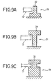
- FIGS. 9A , 9 B, and 9 C are sectional views showing three examples of the first type of inside abutting part 21 .
- This first type of inside abutting part 21 is a stationary column having a groove against which at least one of the top surface and bottom surface of the outer circumference of the disk-shaped storage medium D can slidingly abut.
- FIG. 9A shows a stationary column 22 having a groove against which the bottom surface of the outer circumference of the disk D can slidingly abut
- FIG. 9B shows a stationary column 23 having a groove against which the top surface of the outer circumference of the disk D can slidingly abut
- FIG. 9C shows a stationary column 24 having a groove against which both the top surface of the outer circumference and the bottom surface of the outer circumference of the disk D can slidingly abut.
- FIGS. 10A , 10 B, and 10 C are sectional views showing three examples of the second type of the inside abutting part 21 .
- This second type of inside abutting part 21 is a pulley against which at least one of the top surface and bottom surface of the outer circumference of the disk-shaped storage medium D can rotatably abut.
- FIG. 10A shows a pulley 25 against which the bottom surface of the outer circumference of the disk D can rotatably abut
- FIG. 10B shows a pulley 26 against which the top surface of the outer circumference of the disk D can rotatably abut
- FIG. 10C shows a pulley 26 against which both the bottom surface of the outer circumference and the top surface of the outer circumference of the disk D can rotatably abut.
- FIG. 11A is a plan view showing a second embodiment of the present invention, while FIG. 11B is a front sectional view of the same. Note that to facilitate understanding, parts which originally are not visible are also drawn by solid lines.
- the offset drive function unit 10 in the second embodiment is comprised of an offset loading/ejection drive part (loading/ejection roller) 31 giving a drive force for inserting and taking out the disk-shaped storage medium D and a guide part 32 paired with the loading/ejection roller ( 31 ) and gripping the disk-shaped storage medium D in a transportable manner.
- the width (W) in the vertical plane passing through the axis (X-X) of the loading/ejection roller ( 31 ) forming a space between the cross-sections of the loading/ejection roller ( 31 ) and guide part 32 taken along that vertical plane is made to increase gradually the further toward the offset direction along the axis (X-X) of the loading/ejection roller ( 31 ).
- the guide part 32 is comprised of a guide plate 33 extending horizontally along the above loading/ejection direction (B in FIG. 3 ) and an inside guide rail 34 for pulling and moving the outer circumference of the disk-shaped storage medium D at the inside of an arc to hold the loading/ejection path in an arc shape when the drive of the loading/ejection roller ( 31 ) causes the center O of the disk-shaped storage medium D to draw a substantially arc-shaped loading/ejection path.
- this facing member may also be made a guide roller. This is shown in FIGS. 12A and 12B .
- FIG. 12A is a plan view showing a modification of the second embodiment of the present invention, while FIG. 12B is a front sectional view of the same.
- the guide part 32 in the modification of the second embodiment is comprised of a guide roller 35 which rotates while gripping the disk-shaped storage medium D with the loading/ejection roller ( 31 ) and an inside guide rail 34 which pulls and moves the outer circumference of the disk-shaped storage medium D along the inside of an arc and holds the loading/ejection path at an arc shape when drive of the loading/ejection roller ( 31 ) causes the center O of the disk-shaped storage medium to draw a substantially arc-shaped loading/ejection path.
- the offset loading/ejection drive part 31 and the guide plate 33 or guide roller 35 of the guide part 32 transport the disk D gripped by them so as to draw a curved loading/ejection path.
- the path drawn due to this transport alone will not be an accurate, stable arc. Therefore, the movement of the disk D is linked with the inside guide rail 34 of the guide part 32 as well so as to forcibly correct the path of the disk D to an arc shape.
- the inside surface of the inside guide rail 34 is preferably provided with a rubber member 36 of a suitable hardness. Note that the previously mentioned rollers ( 11 , 31 ) are also preferably made of rubber.
- the third embodiment can be applied in common to the above first embodiment and second embodiment and relates to the outside movement limiting function unit 13 shown in FIG. 1 .
- the outside movement limiting function unit 13 is a final path correcting function unit for making the loading/ejection path of the disk D reliably approach an arc-shaped path (B). It provides beneficial functions in addition to this path correction function too.
- This third embodiment will be explained with reference to the drawings.
- FIGS. 13A , 13 B, 13 C, and 13 D are plan views for explaining the third embodiment of the present invention and show four processes when the disk D is loaded from the opening 3 . To facilitate understanding, however, the processes are assumed to start from ( 13 D), proceed through ( 13 D)->( 13 C)->( 13 B)->and end at ( 13 A).
- an outside movement limiter ( 41 ) (see 3 in FIG. 1 ) holding the loading/ejection path in an arc shape by having the outer circumference of the disk-shaped storage medium D follow the outside of an arc when the aforementioned offset (B) causes the center O of the disk-shaped storage medium D to draw an arc-shaped loading/ejection path.
- the outside movement limiter 41 a guide rail, guide roller, or other various parts may be used, but according to the example shown in FIGS. 13A to 13D , the outside movement limiter 41 is comprised of a lever with one end axially supported by a shaft 42 and with another end able to swing freely in the radial direction R of the disk-shaped storage medium D (see FIG. 13D ).
- the disk moves to the state of FIG. 13C while being corrected in path. That is, the outside movement limiter 41 is pressed against the outer circumference of the disk-shaped storage medium D whereby its other end moves to a predetermined position ( 14 C).
- a detecting function unit is provided for detecting that position ( 14 C).
- This detecting function unit is shown by reference numeral 41 in the figure and specifically is a so-called “limit switch”.
- This limit switch may be a mechanical switch contacting the other end of the lever ( 41 ), but may also be a magnetic type or optical type non-contact switch.
- an inside movement limiting function unit 12 ( 21 to 27 , 34 ) for holding a loading/ejection path in an arc shape by having the outer circumference of the disk D follow along the inside of an arc shape when the center O of the disk D draws an arc-shaped loading/ejection path.
- the distance between the inside movement limiting function unit 12 and the above predetermined position ( 13 C) is set to be slightly smaller than the diameter of the disk D.
- a lever movable holder 43 is changed slightly in orientation in the counterclockwise direction K as shown by FIG. 13B .
- the lever ( 41 ) as a whole also changes in orientation slightly in this direction. Therefore, the clearance between the front end of the lever ( 41 ) and the inside movement limiting function unit 12 widens somewhat and the disk D gently makes a soft landing in a disk holding member 5 ( FIG. 3 ) through its prior inertia.
- the other end of the outside movement limiter 41 can move further outward from that predetermined position.
- the lever movable holder 43 may be made to rotate further in the direction K as shown from FIG. 13B to FIG. 13A .
- outside movement limiter 41 and the detecting function unit 51 shown in FIGS. 13A to 13D are drawn to facilitate understanding of their functions.
- the actual disk device differs from the configuration and layout shown in FIGS. 13A to 13D .
- the present invention can be applied to audio systems or computer systems etc. where a plurality of disk-shaped storage media are stored in a single housing and any of them is automatically loaded, played back/recorded, and then ejected. It is particularly advantageous for reducing the size of the system.
Landscapes
- Automatic Disk Changers (AREA)
- Feeding And Guiding Record Carriers (AREA)
Abstract
Description
-
- (i) The offset
drive function unit 10 has an offset loading/ejection drive part for giving the drive force for inserting and taking out a disk-shaped storage medium D. Here, the offset loading/ejection drive part is comprised of a drive roller. The drive roller is given a substantially V-sectional shape where the radius of the drive roller is gradually increased from the center toward the left and right along the axial direction. Here, - (ii) the substantially V-sectional shape of the drive roller is made a shape left-right asymmetric from the center or
- (iii) the substantially V-sectional shape of the drive roller is made a shape left-right symmetric to from the center.
- (i) The offset
-
- (iv) The offset
drive function unit 10 has a holdingpart 15 paired with the drive roller and holding the disk-shaped storage medium D in a transportable manner. The holding part also has a substantially V-sectional shape at the side facing the drive roller. Here, - (v) the substantially V-sectional shape of the holding
part 15 is made a shape left-right asymmetric from the center or - (vi) the substantially V-sectional shape of the holding
part 15 is made a shape left-right symmetric from the center.
- (iv) The offset
Claims (27)
Applications Claiming Priority (4)
| Application Number | Priority Date | Filing Date | Title |
|---|---|---|---|
| JP2005-049099 | 2005-02-24 | ||
| JP2005049099 | 2005-02-24 | ||
| JP2006031490A JP4740758B2 (en) | 2005-02-24 | 2006-02-08 | Disc-shaped recording medium insertion / extraction mechanism, disc device, and disc autochanger |
| JP2006-031490 | 2006-02-08 |
Publications (2)
| Publication Number | Publication Date |
|---|---|
| US20060190950A1 US20060190950A1 (en) | 2006-08-24 |
| US7600236B2 true US7600236B2 (en) | 2009-10-06 |
Family
ID=36914370
Family Applications (1)
| Application Number | Title | Priority Date | Filing Date |
|---|---|---|---|
| US11/362,293 Expired - Fee Related US7600236B2 (en) | 2005-02-24 | 2006-02-23 | Disk-shaped storage medium loading/ejection mechanism, disk device, and disk autochanger |
Country Status (2)
| Country | Link |
|---|---|
| US (1) | US7600236B2 (en) |
| JP (1) | JP4740758B2 (en) |
Citations (5)
| Publication number | Priority date | Publication date | Assignee | Title |
|---|---|---|---|---|
| US5204849A (en) * | 1989-08-11 | 1993-04-20 | Pioneer Electronic Corporation | Disk playback apparatus with centering device for different disk sizes |
| US5719844A (en) | 1994-11-02 | 1998-02-17 | Alpine Electronics, Inc. | Disc loading/ejecting mechanism and a disc player including same |
| JP2001076408A (en) | 1999-09-08 | 2001-03-23 | Ricoh Co Ltd | Information recording medium drive |
| US20030165104A1 (en) | 2002-02-27 | 2003-09-04 | Shinwa Kabushiki Kaisha | Disk insertion position setting device |
| US20040098735A1 (en) * | 2002-11-14 | 2004-05-20 | Lg Electronics Inc. | Disk loading apparatus for a disk drive |
Family Cites Families (6)
| Publication number | Priority date | Publication date | Assignee | Title |
|---|---|---|---|---|
| JPH0750056A (en) * | 1994-05-23 | 1995-02-21 | Pioneer Electron Corp | Disc player |
| JPH10188431A (en) * | 1996-12-19 | 1998-07-21 | Sony Corp | Disc changer |
| JPH10340513A (en) * | 1997-06-06 | 1998-12-22 | Alpine Electron Inc | Disk device |
| US6418327B1 (en) * | 1999-04-06 | 2002-07-09 | Spike Broadband Systems, Inc. | Methods and determining an optimum sector distribution within a coverage area of a wireless communication system |
| JP3754301B2 (en) * | 2001-01-26 | 2006-03-08 | 三洋電機株式会社 | Disk drive device |
| US6771932B2 (en) * | 2002-05-24 | 2004-08-03 | Omnilux, Inc. | Method and system for automatically determining lines of sight between nodes |
-
2006
- 2006-02-08 JP JP2006031490A patent/JP4740758B2/en not_active Expired - Fee Related
- 2006-02-23 US US11/362,293 patent/US7600236B2/en not_active Expired - Fee Related
Patent Citations (7)
| Publication number | Priority date | Publication date | Assignee | Title |
|---|---|---|---|---|
| US5204849A (en) * | 1989-08-11 | 1993-04-20 | Pioneer Electronic Corporation | Disk playback apparatus with centering device for different disk sizes |
| US5719844A (en) | 1994-11-02 | 1998-02-17 | Alpine Electronics, Inc. | Disc loading/ejecting mechanism and a disc player including same |
| JP2001076408A (en) | 1999-09-08 | 2001-03-23 | Ricoh Co Ltd | Information recording medium drive |
| US20030165104A1 (en) | 2002-02-27 | 2003-09-04 | Shinwa Kabushiki Kaisha | Disk insertion position setting device |
| CN1441426A (en) | 2002-02-27 | 2003-09-10 | 信和株式会社 | Corrector for disc insert position |
| US20040098735A1 (en) * | 2002-11-14 | 2004-05-20 | Lg Electronics Inc. | Disk loading apparatus for a disk drive |
| US20040098736A1 (en) * | 2002-11-14 | 2004-05-20 | Lg Electronics Inc. | Disk loading apparatus for a disk drive |
Non-Patent Citations (2)
| Title |
|---|
| Patent Abstract of Japan, Publication No. 2001076408 A, published Mar. 23, 2001, in the name of Ootsu, et al. |
| Patent Certificate for corresponding Chinese Patent No. CN 100476970C which cites the above-identified listed references. |
Also Published As
| Publication number | Publication date |
|---|---|
| JP2006269047A (en) | 2006-10-05 |
| US20060190950A1 (en) | 2006-08-24 |
| JP4740758B2 (en) | 2011-08-03 |
Similar Documents
| Publication | Publication Date | Title |
|---|---|---|
| US7600236B2 (en) | Disk-shaped storage medium loading/ejection mechanism, disk device, and disk autochanger | |
| US20030235131A1 (en) | Apparatus for loading a disk in an optical disk player | |
| JP2009176385A (en) | Disk drive device | |
| US7162725B2 (en) | Disc centering device | |
| TWI310932B (en) | Disc player | |
| KR100672143B1 (en) | Disc player | |
| CN100476970C (en) | Disk-shaped storage medium loading/ejection mechanism, disk device, and disk autochanger | |
| US7302695B2 (en) | Slot-in type optical disk player | |
| JP2006048837A (en) | Disk player | |
| JP2003257107A (en) | Disk insertion positioning device | |
| JP3949855B2 (en) | Recording medium playback device | |
| JP4106422B2 (en) | Disc guide mechanism and disc playback apparatus using the disc guide mechanism | |
| US7284251B2 (en) | Disc-guiding member provided with a positioning pillar | |
| JP2587459Y2 (en) | Disc-shaped recording medium insertion / ejection device | |
| JP4267616B2 (en) | Disk transport mechanism | |
| JP4246686B2 (en) | Disc insertion restriction device | |
| JP3796215B2 (en) | Disc player | |
| JP4308201B2 (en) | Recording medium driving device | |
| JP2008021381A (en) | Loading mechanism for disk device | |
| JP2006048838A (en) | Disk player | |
| JP3900678B2 (en) | Loading mechanism | |
| JP2004199831A (en) | Disk player | |
| JP2004280959A (en) | Disk player | |
| JP3820934B2 (en) | Optical disk device | |
| KR19980023460A (en) | Disc guiding device for optical disc player |
Legal Events
| Date | Code | Title | Description |
|---|---|---|---|
| AS | Assignment |
Owner name: FUJITSU TEN LIMITED, JAPAN Free format text: ASSIGNMENT OF ASSIGNORS INTEREST;ASSIGNORS:OGAWA, KOUICHI;FUJIMOTO, FUMIHIKO;YAMANAKA, YASUTAKE;AND OTHERS;REEL/FRAME:017489/0668 Effective date: 20060210 Owner name: MURAMOTO INDUSTRY CO., LTD., JAPAN Free format text: ASSIGNMENT OF ASSIGNORS INTEREST;ASSIGNORS:OGAWA, KOUICHI;FUJIMOTO, FUMIHIKO;YAMANAKA, YASUTAKE;AND OTHERS;REEL/FRAME:017489/0668 Effective date: 20060210 |
|
| STCF | Information on status: patent grant |
Free format text: PATENTED CASE |
|
| FEPP | Fee payment procedure |
Free format text: PAYOR NUMBER ASSIGNED (ORIGINAL EVENT CODE: ASPN); ENTITY STATUS OF PATENT OWNER: LARGE ENTITY |
|
| FPAY | Fee payment |
Year of fee payment: 4 |
|
| FPAY | Fee payment |
Year of fee payment: 8 |
|
| FEPP | Fee payment procedure |
Free format text: MAINTENANCE FEE REMINDER MAILED (ORIGINAL EVENT CODE: REM.); ENTITY STATUS OF PATENT OWNER: LARGE ENTITY |
|
| LAPS | Lapse for failure to pay maintenance fees |
Free format text: PATENT EXPIRED FOR FAILURE TO PAY MAINTENANCE FEES (ORIGINAL EVENT CODE: EXP.); ENTITY STATUS OF PATENT OWNER: LARGE ENTITY |
|
| STCH | Information on status: patent discontinuation |
Free format text: PATENT EXPIRED DUE TO NONPAYMENT OF MAINTENANCE FEES UNDER 37 CFR 1.362 |
|
| FP | Lapsed due to failure to pay maintenance fee |
Effective date: 20211006 |