US7597134B2 - Heat dissipation device with a heat pipe - Google Patents
Heat dissipation device with a heat pipe Download PDFInfo
- Publication number
- US7597134B2 US7597134B2 US11/683,373 US68337307A US7597134B2 US 7597134 B2 US7597134 B2 US 7597134B2 US 68337307 A US68337307 A US 68337307A US 7597134 B2 US7597134 B2 US 7597134B2
- Authority
- US
- United States
- Prior art keywords
- fins
- heat
- heat pipes
- portions
- evaporating
- Prior art date
- Legal status (The legal status is an assumption and is not a legal conclusion. Google has not performed a legal analysis and makes no representation as to the accuracy of the status listed.)
- Expired - Fee Related
Links
- 230000017525 heat dissipation Effects 0.000 title claims abstract description 26
- 238000001704 evaporation Methods 0.000 claims abstract description 30
- 229910052751 metal Inorganic materials 0.000 description 7
- 239000002184 metal Substances 0.000 description 7
- 239000007788 liquid Substances 0.000 description 2
- RYGMFSIKBFXOCR-UHFFFAOYSA-N Copper Chemical compound [Cu] RYGMFSIKBFXOCR-UHFFFAOYSA-N 0.000 description 1
- 239000003570 air Substances 0.000 description 1
- 229910052782 aluminium Inorganic materials 0.000 description 1
- XAGFODPZIPBFFR-UHFFFAOYSA-N aluminium Chemical compound [Al] XAGFODPZIPBFFR-UHFFFAOYSA-N 0.000 description 1
- 239000012080 ambient air Substances 0.000 description 1
- 238000013459 approach Methods 0.000 description 1
- 238000001816 cooling Methods 0.000 description 1
- 229910052802 copper Inorganic materials 0.000 description 1
- 239000010949 copper Substances 0.000 description 1
- 239000012530 fluid Substances 0.000 description 1
- 239000007792 gaseous phase Substances 0.000 description 1
- 239000007791 liquid phase Substances 0.000 description 1
- 239000000463 material Substances 0.000 description 1
- 238000000034 method Methods 0.000 description 1
- 239000012071 phase Substances 0.000 description 1
- 239000007787 solid Substances 0.000 description 1
Images


Classifications
-
- F—MECHANICAL ENGINEERING; LIGHTING; HEATING; WEAPONS; BLASTING
- F28—HEAT EXCHANGE IN GENERAL
- F28D—HEAT-EXCHANGE APPARATUS, NOT PROVIDED FOR IN ANOTHER SUBCLASS, IN WHICH THE HEAT-EXCHANGE MEDIA DO NOT COME INTO DIRECT CONTACT
- F28D15/00—Heat-exchange apparatus with the intermediate heat-transfer medium in closed tubes passing into or through the conduit walls ; Heat-exchange apparatus employing intermediate heat-transfer medium or bodies
- F28D15/02—Heat-exchange apparatus with the intermediate heat-transfer medium in closed tubes passing into or through the conduit walls ; Heat-exchange apparatus employing intermediate heat-transfer medium or bodies in which the medium condenses and evaporates, e.g. heat pipes
- F28D15/0275—Arrangements for coupling heat-pipes together or with other structures, e.g. with base blocks; Heat pipe cores
-
- F—MECHANICAL ENGINEERING; LIGHTING; HEATING; WEAPONS; BLASTING
- F28—HEAT EXCHANGE IN GENERAL
- F28D—HEAT-EXCHANGE APPARATUS, NOT PROVIDED FOR IN ANOTHER SUBCLASS, IN WHICH THE HEAT-EXCHANGE MEDIA DO NOT COME INTO DIRECT CONTACT
- F28D15/00—Heat-exchange apparatus with the intermediate heat-transfer medium in closed tubes passing into or through the conduit walls ; Heat-exchange apparatus employing intermediate heat-transfer medium or bodies
- F28D15/02—Heat-exchange apparatus with the intermediate heat-transfer medium in closed tubes passing into or through the conduit walls ; Heat-exchange apparatus employing intermediate heat-transfer medium or bodies in which the medium condenses and evaporates, e.g. heat pipes
- F28D15/0233—Heat-exchange apparatus with the intermediate heat-transfer medium in closed tubes passing into or through the conduit walls ; Heat-exchange apparatus employing intermediate heat-transfer medium or bodies in which the medium condenses and evaporates, e.g. heat pipes the conduits having a particular shape, e.g. non-circular cross-section, annular
-
- H—ELECTRICITY
- H01—ELECTRIC ELEMENTS
- H01L—SEMICONDUCTOR DEVICES NOT COVERED BY CLASS H10
- H01L23/00—Details of semiconductor or other solid state devices
- H01L23/34—Arrangements for cooling, heating, ventilating or temperature compensation ; Temperature sensing arrangements
- H01L23/40—Mountings or securing means for detachable cooling or heating arrangements ; fixed by friction, plugs or springs
- H01L23/4006—Mountings or securing means for detachable cooling or heating arrangements ; fixed by friction, plugs or springs with bolts or screws
-
- H—ELECTRICITY
- H01—ELECTRIC ELEMENTS
- H01L—SEMICONDUCTOR DEVICES NOT COVERED BY CLASS H10
- H01L23/00—Details of semiconductor or other solid state devices
- H01L23/34—Arrangements for cooling, heating, ventilating or temperature compensation ; Temperature sensing arrangements
- H01L23/42—Fillings or auxiliary members in containers or encapsulations selected or arranged to facilitate heating or cooling
- H01L23/427—Cooling by change of state, e.g. use of heat pipes
-
- H—ELECTRICITY
- H01—ELECTRIC ELEMENTS
- H01L—SEMICONDUCTOR DEVICES NOT COVERED BY CLASS H10
- H01L23/00—Details of semiconductor or other solid state devices
- H01L23/34—Arrangements for cooling, heating, ventilating or temperature compensation ; Temperature sensing arrangements
- H01L23/46—Arrangements for cooling, heating, ventilating or temperature compensation ; Temperature sensing arrangements involving the transfer of heat by flowing fluids
- H01L23/467—Arrangements for cooling, heating, ventilating or temperature compensation ; Temperature sensing arrangements involving the transfer of heat by flowing fluids by flowing gases, e.g. air
-
- H—ELECTRICITY
- H01—ELECTRIC ELEMENTS
- H01L—SEMICONDUCTOR DEVICES NOT COVERED BY CLASS H10
- H01L2924/00—Indexing scheme for arrangements or methods for connecting or disconnecting semiconductor or solid-state bodies as covered by H01L24/00
- H01L2924/0001—Technical content checked by a classifier
- H01L2924/0002—Not covered by any one of groups H01L24/00, H01L24/00 and H01L2224/00
Definitions
- the present invention generally relates to heat dissipation devices, and more particularly to a heat dissipation device having a heat pipe for cooling an electronic component, such as an integrated circuit package.
- Electronic components such as central processing units (CPUs) comprise numerous circuits operating at high speed and generating substantial heat. Under most circumstances, it is necessary to cool the CPUs in order to maintain safe operating conditions and assure that the CPUs function properly and reliably.
- various approaches have been used to cool electronic components.
- a finned metal heat sink is attached to an outer surface of the CPU to remove the heat therefrom. The heat absorbed by the heat sink is then dissipated to ambient air.
- the related finned metal heat sink is made of highly heat-conductive metal, such as copper or aluminum, and generally comprises a solid metal base for contacting with the CPU to absorb the heat therefrom and a plurality of fins formed on the base for dissipating the heat.
- U.S. Pat. No. 6,163,073 shows an integrated heat sink with heat pipes.
- the heat sink has a cast base plate and vertically extending fins, the fins being cast integrally with the base plate.
- the base plate has elongated grooves that extend along a bottom of the base plate.
- Elongated heat pipes are disposed in the elongated grooves for contacting with heat sink and the CPU.
- the related art indicates that this structure reduces thermal gradients in the heat sink.
- the area of the base in contact with the CPU is greater than the area of the heat pipe in contact with the CPU. The heat of the base of the heat sink still cannot be transferred to the whole heat sink quickly enough.
- Another technique for dissipating heat includes a base including an envelope filled with working liquid (i.e. vapor chamber).
- This kind of heat dissipation device includes a heat sink in contact with the base.
- the working fluid circulates between a liquid phase and a gaseous phase in the vapor chamber in such a manner that heat is taken up at a point that is in contact with the CPU, and the heat is released at a point in contact with a heat sink.
- This structure has better heat dissipation, but it is complex and expensive.
- a heat dissipation device comprises at least two heat pipes and a plurality of fins thermally connected with the heat pipes.
- Each of the heat pipes comprises a flattened evaporating portion and a condensing portion.
- the evaporating portions are closely connected with each other.
- a flat bottom surface of the evaporating portions of the heat pipes directly engages with an electronic component.
- a flat top surface of the evaporating portions of the heat pipes directly engages with a bottom surface of the fins.
- the condensing portions of the heat pipes extending through the fins.
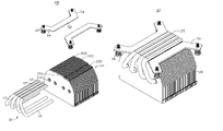
- FIG. 1 is an exploded, isometric view of a heat dissipation device in accordance with a preferred embodiment of the present invention
- FIG. 2 is an inverted view of FIG. 1 ;
- FIG. 3 is an assembled view of FIG. 1 ;
- FIG. 4 is an assembled view of FIG. 2 .
- the heat dissipation device 100 can be mounted to a printed circuit board (not shown) to remove heat from a heat-generating electronic device (not shown) mounted on the printed circuit board, such as a CPU (not shown).
- the heat dissipation device 100 comprises a plurality of fins 20 and four heat pipes 10 connecting the CPU and the fins 20 .
- the heat dissipation device 100 further comprises two locking members 50 soldered to two opposite bottom sides of the fins 20 to secure the heat dissipation device 100 to the printed circuit board.
- the heat pipes 10 are U-shaped. Each heat pipe 10 comprises a horizontal evaporating portion 12 , a condensing portion 14 parallel to the evaporating portion 12 and an adiabatic portion 13 , connecting the evaporating portion 12 and the condensing portion 14 .
- the evaporating portions 12 of the heat pipes 10 are flattened, which means that their bottom surface 125 and top surface 120 are both flat and coplanar.
- the evaporating portions 12 of the heat pipes 10 are closely connected with each other, without a significant gap therebetween. Thus, the evaporating portions 12 act as a base for directly contacting with a top surface of the CPU and a bottom surface of the fins 20 .
- the condensing portions 14 of the heat pipes 10 spread out and extend through the fins 20 .
- the fins 20 are oriented perpendicular to the evaporating portions 12 of the heat pipes 10 and parallel to each other.
- the fins 20 each comprise a thin sheet metal plate 21 which has a U-shaped configuration.
- a central portion of the bottom surface of the fins 20 protrudes perpendicularly and downwardly a protrusion 221 such that a pair of receiving spaces (not labeled) are symmetrically formed at flanks of the protrusion 221 for receiving the corresponding locking members 50 therein.
- Flanges 220 , 225 are bent from the bottom surface of the fins 20 .
- the flanges 225 are engaged with the top surface 120 of the evaporating portions 12 of the heat pipes 10 and the other flanges 220 located at flanks of the flanges 225 are engaged with the locking members 50 .
- the top surface 120 of the evaporating portions 12 of the heat pipes 10 is soldered on the flanges 225 .
- the flanges 220 , 225 separate the fins 20 at uniform intervals.
- the fins 20 define holes 210 in the plates 21 to define channels (not labeled) for receiving the condensing portions 14 of the heat pipes 10 .
- Each locking member 50 comprises a locking beam 52 soldered to the corresponding flanges 220 of the fins 20 and two legs 54 extending outwardly from opposite ends of the locking beam 52 at an angle to the locking beam 52 .
- the legs 54 define apertures therein for extending screws 60 therethrough to engage with a retainer (not shown), thereby mounting the heat dissipation device 100 to the printed circuit board.
- the base formed by the evaporating portions 12 of the heat pipes 10 is disposed on the top surface of the CPU. Heat generated by the CPU is conducted to the evaporating portions 12 via the bottom surface 125 . Then a part of the heat accumulated on the evaporating portions 12 is transferred to the fins 20 via the adiabatic portions 13 and the condensing portions 14 of the heat pipes 10 . Another part of the heat accumulated on the evaporating portions 12 is directly transferred to the fins 20 via the top surface 120 of the evaporating portions 12 . Finally, the heat is dissipated to surrounding air by the fins 20 .
- the flattened evaporating portions 12 of the heat pipes 10 act as the base to have a large area contact with the CPU to absorb heat therefrom; thus, the heat dissipation device 100 can efficiently absorb the heat and dissipate the heat of the CPU.
- the heat dissipation efficiency of the heat dissipation device 100 can be improved.
Abstract
Description
Claims (2)
Priority Applications (1)
| Application Number | Priority Date | Filing Date | Title |
|---|---|---|---|
| US11/683,373 US7597134B2 (en) | 2007-03-07 | 2007-03-07 | Heat dissipation device with a heat pipe |
Applications Claiming Priority (1)
| Application Number | Priority Date | Filing Date | Title |
|---|---|---|---|
| US11/683,373 US7597134B2 (en) | 2007-03-07 | 2007-03-07 | Heat dissipation device with a heat pipe |
Publications (2)
| Publication Number | Publication Date |
|---|---|
| US20080216990A1 US20080216990A1 (en) | 2008-09-11 |
| US7597134B2 true US7597134B2 (en) | 2009-10-06 |
Family
ID=39740474
Family Applications (1)
| Application Number | Title | Priority Date | Filing Date |
|---|---|---|---|
| US11/683,373 Expired - Fee Related US7597134B2 (en) | 2007-03-07 | 2007-03-07 | Heat dissipation device with a heat pipe |
Country Status (1)
| Country | Link |
|---|---|
| US (1) | US7597134B2 (en) |
Cited By (10)
| Publication number | Priority date | Publication date | Assignee | Title |
|---|---|---|---|---|
| US20090178787A1 (en) * | 2008-01-11 | 2009-07-16 | Tsung-Hsien Huang | Cooler module without base panel |
| US20090260782A1 (en) * | 2008-04-17 | 2009-10-22 | Aavid Thermalloy, Llc | Heat sink base plate with heat pipe |
| US20110114293A1 (en) * | 2009-11-16 | 2011-05-19 | Kuo-Len Lin | Manufacturing method, finished product and fixture of coplanar evaporators of multiple heat pipes |
| US20110214842A1 (en) * | 2010-03-05 | 2011-09-08 | Lea-Min Technologies Co., Ltd. | Heat sink |
| CN102573386A (en) * | 2010-12-20 | 2012-07-11 | 富准精密工业(深圳)有限公司 | Cooling module and manufacturing method thereof |
| US20120305221A1 (en) * | 2011-06-02 | 2012-12-06 | Tsung-Hsien Huang | Heat pipe-attached heat sink |
| US20130008629A1 (en) * | 2011-07-05 | 2013-01-10 | Chun-Ming Wu | Thermal module and method of manufacturing same |
| US20130098584A1 (en) * | 2009-09-18 | 2013-04-25 | Golden Sun News Techniques Co., Ltd. | Heat conducting structure with coplanar heated portion, manufacturing method thereof, and heat sink therewith |
| US20230320034A1 (en) * | 2022-03-22 | 2023-10-05 | Baidu Usa Llc | Thermal management device for high density processing unit |
| US20230345669A1 (en) * | 2022-04-20 | 2023-10-26 | Quanta Computer Inc. | Heat-Absorbing Chassis For Fan-Less Electronic Component |
Families Citing this family (15)
| Publication number | Priority date | Publication date | Assignee | Title |
|---|---|---|---|---|
| US7609521B2 (en) * | 2007-09-26 | 2009-10-27 | Fu Zhun Precision Industry (Shen Zhen) Co., Ltd. | Heat dissipation device with a heat pipe |
| US7650929B2 (en) * | 2007-09-30 | 2010-01-26 | Tsung-Hsien Huang | Cooler module |
| EP2211135B1 (en) * | 2009-01-22 | 2013-05-29 | Cpumate Inc. | Fins-type heat sink and method for assembling the same |
| CN101868134A (en) * | 2009-04-14 | 2010-10-20 | 鸿富锦精密工业(深圳)有限公司 | Heat radiator and manufacture method thereof |
| TWI407897B (en) * | 2009-07-29 | 2013-09-01 | Golden Sun News Tech Co Ltd | Method of thermo conductor having coplanar evaporator sections |
| US20140041838A1 (en) * | 2009-09-04 | 2014-02-13 | Golden Sun News Techniques Co., Ltd | Heat pipe assembly and heat dissipation device having the same |
| EP2312626B1 (en) | 2009-09-10 | 2013-07-31 | Cpumate Inc. | Heat pipe assembly |
| TW201037256A (en) * | 2010-05-14 | 2010-10-16 | Asia Vital Components Co Ltd | Heat dissipating device and manufacturing method thereof |
| US20120080169A1 (en) * | 2010-10-04 | 2012-04-05 | Chien-Yen Lu | Heat sink |
| US20130186608A1 (en) * | 2012-01-20 | 2013-07-25 | C.C. Lathe Enterprise Co., Ltd | Heat dissipating device |
| US9379039B2 (en) * | 2013-09-04 | 2016-06-28 | Cisco Technology, Inc. | Heat transfer for electronic equipment |
| US9429370B1 (en) * | 2014-05-27 | 2016-08-30 | Unigen Corporation | Heat sink with flat heat pipe |
| US10045464B1 (en) | 2017-03-31 | 2018-08-07 | International Business Machines Corporation | Heat pipe and vapor chamber heat dissipation |
| CN107968078A (en) * | 2017-11-14 | 2018-04-27 | 华南理工大学 | Heat pipe embedded-type heat-dissipating device and its manufacture method |
| CN116360554A (en) * | 2021-12-28 | 2023-06-30 | 全亿大科技(佛山)有限公司 | Radiator and radiator manufacturing method |
Citations (16)
| Publication number | Priority date | Publication date | Assignee | Title |
|---|---|---|---|---|
| US6717813B1 (en) | 2003-04-14 | 2004-04-06 | Thermal Corp. | Heat dissipation unit with direct contact heat pipe |
| CN2717019Y (en) | 2004-06-04 | 2005-08-10 | 东莞莫仕连接器有限公司 | Heat sink assembly |
| CN2762348Y (en) | 2004-12-31 | 2006-03-01 | 协禧电机股份有限公司 | Heat sink |
| US20060054307A1 (en) * | 2004-09-15 | 2006-03-16 | Foxconn Technology Co., Ltd. | Heat sink |
| CN2769980Y (en) | 2005-01-06 | 2006-04-05 | 富准精密工业(深圳)有限公司 | Liquid cooling radiator |
| CN2770090Y (en) | 2004-10-29 | 2006-04-05 | 鸿富锦精密工业(深圳)有限公司 | Radiating apparatus |
| US7100681B1 (en) * | 2005-10-31 | 2006-09-05 | Foxconn Technology Co., Ltd. | Heat dissipation device having heat pipe |
| US20070006997A1 (en) * | 2005-07-07 | 2007-01-11 | Ama Precision Inc. | Heat sink structure |
| US20070097646A1 (en) * | 2005-11-02 | 2007-05-03 | Xue-Wen Peng | Heat dissipating apparatus for computer add-on cards |
| US20070107871A1 (en) * | 2005-11-17 | 2007-05-17 | Foxconn Technology Co., Ltd. | Heat sink |
| US20070267177A1 (en) * | 2006-05-16 | 2007-11-22 | Kuo-Len Lin | Juxtaposing Structure For Heated Ends Of Heat Pipes |
| US20070267181A1 (en) * | 2006-05-16 | 2007-11-22 | Kuo-Len Lin | Juxtaposing Structure For Heated Ends Of Heat Pipes |
| US20070272395A1 (en) * | 2006-05-25 | 2007-11-29 | Foxconn Technology Co., Ltd. | Heat dissipation device |
| US20080028610A1 (en) * | 2006-07-26 | 2008-02-07 | Shyh-Ming Chen | Method for assembling a vertical heat radiator |
| US20080047693A1 (en) * | 2006-08-22 | 2008-02-28 | Shyh-Ming Chen | Cooler |
| US7394656B1 (en) * | 2006-12-09 | 2008-07-01 | Hong Fu Jin Precision Industry (Shenzhen) Co., Ltd. | Heat dissipation device |
-
2007
- 2007-03-07 US US11/683,373 patent/US7597134B2/en not_active Expired - Fee Related
Patent Citations (16)
| Publication number | Priority date | Publication date | Assignee | Title |
|---|---|---|---|---|
| US6717813B1 (en) | 2003-04-14 | 2004-04-06 | Thermal Corp. | Heat dissipation unit with direct contact heat pipe |
| CN2717019Y (en) | 2004-06-04 | 2005-08-10 | 东莞莫仕连接器有限公司 | Heat sink assembly |
| US20060054307A1 (en) * | 2004-09-15 | 2006-03-16 | Foxconn Technology Co., Ltd. | Heat sink |
| CN2770090Y (en) | 2004-10-29 | 2006-04-05 | 鸿富锦精密工业(深圳)有限公司 | Radiating apparatus |
| CN2762348Y (en) | 2004-12-31 | 2006-03-01 | 协禧电机股份有限公司 | Heat sink |
| CN2769980Y (en) | 2005-01-06 | 2006-04-05 | 富准精密工业(深圳)有限公司 | Liquid cooling radiator |
| US20070006997A1 (en) * | 2005-07-07 | 2007-01-11 | Ama Precision Inc. | Heat sink structure |
| US7100681B1 (en) * | 2005-10-31 | 2006-09-05 | Foxconn Technology Co., Ltd. | Heat dissipation device having heat pipe |
| US20070097646A1 (en) * | 2005-11-02 | 2007-05-03 | Xue-Wen Peng | Heat dissipating apparatus for computer add-on cards |
| US20070107871A1 (en) * | 2005-11-17 | 2007-05-17 | Foxconn Technology Co., Ltd. | Heat sink |
| US20070267177A1 (en) * | 2006-05-16 | 2007-11-22 | Kuo-Len Lin | Juxtaposing Structure For Heated Ends Of Heat Pipes |
| US20070267181A1 (en) * | 2006-05-16 | 2007-11-22 | Kuo-Len Lin | Juxtaposing Structure For Heated Ends Of Heat Pipes |
| US20070272395A1 (en) * | 2006-05-25 | 2007-11-29 | Foxconn Technology Co., Ltd. | Heat dissipation device |
| US20080028610A1 (en) * | 2006-07-26 | 2008-02-07 | Shyh-Ming Chen | Method for assembling a vertical heat radiator |
| US20080047693A1 (en) * | 2006-08-22 | 2008-02-28 | Shyh-Ming Chen | Cooler |
| US7394656B1 (en) * | 2006-12-09 | 2008-07-01 | Hong Fu Jin Precision Industry (Shenzhen) Co., Ltd. | Heat dissipation device |
Cited By (13)
| Publication number | Priority date | Publication date | Assignee | Title |
|---|---|---|---|---|
| US8191612B2 (en) * | 2008-01-11 | 2012-06-05 | Tsung-Hsien Huang | Cooler module without base panel |
| US20090178787A1 (en) * | 2008-01-11 | 2009-07-16 | Tsung-Hsien Huang | Cooler module without base panel |
| US20090260782A1 (en) * | 2008-04-17 | 2009-10-22 | Aavid Thermalloy, Llc | Heat sink base plate with heat pipe |
| US8286693B2 (en) | 2008-04-17 | 2012-10-16 | Aavid Thermalloy, Llc | Heat sink base plate with heat pipe |
| US20130098584A1 (en) * | 2009-09-18 | 2013-04-25 | Golden Sun News Techniques Co., Ltd. | Heat conducting structure with coplanar heated portion, manufacturing method thereof, and heat sink therewith |
| US8978742B2 (en) * | 2009-09-18 | 2015-03-17 | Cpumate Inc. | Heat conducting structure with coplanar heated portion, manufacturing method thereof, and heat sink therewith |
| US20110114293A1 (en) * | 2009-11-16 | 2011-05-19 | Kuo-Len Lin | Manufacturing method, finished product and fixture of coplanar evaporators of multiple heat pipes |
| US20110214842A1 (en) * | 2010-03-05 | 2011-09-08 | Lea-Min Technologies Co., Ltd. | Heat sink |
| CN102573386A (en) * | 2010-12-20 | 2012-07-11 | 富准精密工业(深圳)有限公司 | Cooling module and manufacturing method thereof |
| US20120305221A1 (en) * | 2011-06-02 | 2012-12-06 | Tsung-Hsien Huang | Heat pipe-attached heat sink |
| US20130008629A1 (en) * | 2011-07-05 | 2013-01-10 | Chun-Ming Wu | Thermal module and method of manufacturing same |
| US20230320034A1 (en) * | 2022-03-22 | 2023-10-05 | Baidu Usa Llc | Thermal management device for high density processing unit |
| US20230345669A1 (en) * | 2022-04-20 | 2023-10-26 | Quanta Computer Inc. | Heat-Absorbing Chassis For Fan-Less Electronic Component |
Also Published As
| Publication number | Publication date |
|---|---|
| US20080216990A1 (en) | 2008-09-11 |
Similar Documents
| Publication | Publication Date | Title |
|---|---|---|
| US7597134B2 (en) | Heat dissipation device with a heat pipe | |
| US7753109B2 (en) | Heat dissipation device with heat pipes | |
| US7779897B2 (en) | Heat dissipation device with heat pipes | |
| US20080128118A1 (en) | Heat dissipation device with a heat pipe | |
| US7269014B1 (en) | Heat dissipation device | |
| US7697293B1 (en) | Heat dissipation device | |
| US7395851B2 (en) | Heat dissipation device | |
| US7443677B1 (en) | Heat dissipation device | |
| US7757751B2 (en) | Heat dissipation device | |
| US7440279B2 (en) | Heat dissipation device | |
| US7548426B2 (en) | Heat dissipation device with heat pipes | |
| US8002019B2 (en) | Heat dissipation device | |
| US7609521B2 (en) | Heat dissipation device with a heat pipe | |
| US7595989B2 (en) | Heat dissipation device | |
| US20090059524A1 (en) | Heat dissipation device | |
| US20070272395A1 (en) | Heat dissipation device | |
| US8381801B2 (en) | Heat dissipation device | |
| US8069909B2 (en) | Heat dissipation device | |
| US7537046B2 (en) | Heat dissipation device with heat pipe | |
| US20060273137A1 (en) | Heat dissipation device with heat pipes | |
| US7870890B2 (en) | Heat dissipation device with heat pipe | |
| US20070169919A1 (en) | Heat pipe type heat dissipation device | |
| US20080289799A1 (en) | Heat dissipation device with a heat pipe | |
| US20080142192A1 (en) | Heat dissipation device with a heat pipe | |
| US7580263B2 (en) | Heat dissipation device with a fan holder |
Legal Events
| Date | Code | Title | Description |
|---|---|---|---|
| AS | Assignment |
Owner name: FOXCONN TECHNOLOGY CO., LTD., TAIWAN Free format text: ASSIGNMENT OF ASSIGNORS INTEREST;ASSIGNORS:MIN, XU-XIN;FU, MENG;CHEN, CHUN-CHI;REEL/FRAME:018977/0245 Effective date: 20070305 |
|
| AS | Assignment |
Owner name: FU ZHUN PRECISION INDUSTRY (SHEN ZHEN) CO., LTD., Free format text: ASSIGNMENT OF ASSIGNORS INTEREST;ASSIGNOR:FOXCONN TECHNOLOGY CO., LTD.;REEL/FRAME:022993/0695 Effective date: 20090710 Owner name: FOXCONN TECHNOLOGY CO., LTD., TAIWAN Free format text: ASSIGNMENT OF ASSIGNORS INTEREST;ASSIGNOR:FOXCONN TECHNOLOGY CO., LTD.;REEL/FRAME:022993/0695 Effective date: 20090710 |
|
| FPAY | Fee payment |
Year of fee payment: 4 |
|
| REMI | Maintenance fee reminder mailed | ||
| LAPS | Lapse for failure to pay maintenance fees |
Free format text: PATENT EXPIRED FOR FAILURE TO PAY MAINTENANCE FEES (ORIGINAL EVENT CODE: EXP.) |
|
| STCH | Information on status: patent discontinuation |
Free format text: PATENT EXPIRED DUE TO NONPAYMENT OF MAINTENANCE FEES UNDER 37 CFR 1.362 |
|
| FP | Lapsed due to failure to pay maintenance fee |
Effective date: 20171006 |