US7589976B1 - Expansion card slot structure - Google Patents
Expansion card slot structure Download PDFInfo
- Publication number
- US7589976B1 US7589976B1 US12/109,448 US10944808A US7589976B1 US 7589976 B1 US7589976 B1 US 7589976B1 US 10944808 A US10944808 A US 10944808A US 7589976 B1 US7589976 B1 US 7589976B1
- Authority
- US
- United States
- Prior art keywords
- fixing pin
- end fixing
- expansion card
- slot
- card slot
- Prior art date
- Legal status (The legal status is an assumption and is not a legal conclusion. Google has not performed a legal analysis and makes no representation as to the accuracy of the status listed.)
- Expired - Fee Related
Links
Images


Classifications
-
- H—ELECTRICITY
- H05—ELECTRIC TECHNIQUES NOT OTHERWISE PROVIDED FOR
- H05K—PRINTED CIRCUITS; CASINGS OR CONSTRUCTIONAL DETAILS OF ELECTRIC APPARATUS; MANUFACTURE OF ASSEMBLAGES OF ELECTRICAL COMPONENTS
- H05K9/00—Screening of apparatus or components against electric or magnetic fields
- H05K9/0007—Casings
Definitions
- the present invention relates to an improved expansion card slot structure, and more particularly to an improved expansion card slot structure that increases the number of electromagnetic interference (EMI) contact points and provides a shorter path for grounding and eliminating noises to improve the electromagnetic interference (EMI) effect.
- EMI electromagnetic interference
- an electronic device such as a TV tuner box or a computer usually installs a port (USB port, network port, mouse port or speaker port, etc) on its main board, and a so-called electromagnetic interference (EMI) device such as a conducting plate is provided for grounding and eliminating noises to provide a good signal transmission quality without being affected by the noises.
- a port USB port, network port, mouse port or speaker port, etc
- EMI electromagnetic interference
- the expansion card slot structure 9 includes a slot base 91 , an insert slot disposed at the front end of the slot base 91 , a rear-end port 912 , and a shield bracket 92 installed at the rear-end port 912 for providing an electromagnetic interference (EMI) effect.
- EMI electromagnetic interference
- the slot base 91 comprises a plurality of fixing pins 93 , each having an upper distal edge 931 and a lower distal edge 932 , wherein the lower distal edge 932 includes a latch portion 933 installed on a main board (not shown in the figure).
- the shield bracket 92 comprises a plurality of contact points 921 in contact respectively with the upper distal edge of each fixing pin 93 .
- the foregoing contact points 921 of the shield bracket 92 are electrically coupled with the upper distal edge 931 of the fixing pin 93 for achieving the effect of grounding and eliminating noises (or known as an electromagnetic interference (EMI) effect).
- EMI electromagnetic interference
- the traditional structural design can achieve the effect of grounding and eliminating noises by contacting the contact point 921 of the shield bracket 92 with the upper distal edge 931 of the fixing pin 93 , but the grounding path is limited to two contact points only, and the path for grounding the noises is longer, and thus the electromagnetic interference (EMI) effect is lowered and the life expectancy of the electronic device is affected adversely.
- EMI electromagnetic interference
- the primary objective of the present invention is to overcome the shortcomings of the prior art by providing an improved expansion card slot structure that comprises a slot base, a plurality of rear-end fixing pins and a shield bracket, wherein the slot base includes a front-end insert slot and a rear-end port, and a plurality of rear-end fixing pins are installed at the slot base and disposed proximate to a rear-end port of the slot base, and each rear-end fixing pin includes a main body portion, an upper end and a lower end.
- the shield bracket is installed at the slot base and covered onto the rear-end port of the slot base, and the shield bracket includes a plurality of contact portions and a plurality of elastic arms, wherein each contact portion is in contact with an upper end of each rear-end fixing pin, and each elastic arm is in contact with a main body portion of each rear-end fixing pin and disposed proximate to a lower end of each rear-end fixing pin.
- the electromagnetic interference (EMI) contact points at the plurality of contact portions and the plurality of elastic arms of the shield bracket are increased, wherein the plurality of elastic arms come with a shorter path for grounding and eliminating noises, and thus the invention can improve the electromagnetic interference (EMI) effect and extend the life expectancy of the electronic devices.
- EMI electromagnetic interference
- FIG. 1 is a perspective view of a traditional expansion card slot structure
- FIG. 2 is an enlarged view of FIG. 1 ;
- FIG. 3 is an exploded view of a preferred embodiment of the present invention.
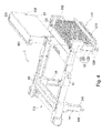
- FIG. 4 is another exploded view of a preferred embodiment of the present invention.
- FIG. 5 is a perspective view of a preferred embodiment of the present invention.
- FIG. 3 shows an exploded view
- FIG. 4 shows another exploded view
- FIG. 5 shows a perspective view of the preferred embodiment of the invention.
- the improved expansion card slot structure 1 comprises a slot base 11 , a plurality of rear-end fixing pins 12 and a shield bracket 13 .
- the slot base 11 includes a front-end insert slot 111 and a rear-end port 112 , wherein the front-end insert slot 111 is a slot for installing an expansion card (not shown in the figure) such as a wireless network card, a memory card and an external hard disk, etc.
- the rear-end port 112 of the slot base 11 includes a plurality of electric pins 113 .
- each rear-end fixing pin 12 is installed at the slot base 11 and disposed proximate to the rear-end port 112 of the slot base 11 , and each rear-end fixing pin 12 includes a main body portion 123 , an upper end 121 and a lower end 122 .
- the shield bracket 13 is installed at the slot base 11 and covered onto the rear-end port 112 of the slot base 11 , and the shield bracket 13 includes a plurality of contact portions 131 and a plurality of elastic arms 132 , wherein each contact portion 131 is in contact with the upper end 121 of each rear-end fixing pin 12 , and each elastic arm 132 is in contact with a main body portion 123 of each rear-end fixing pin 12 and disposed proximate to the lower end 122 of each rear-end fixing pin 12 .
- the improved expansion slot card structure in accordance with the preferred embodiment of the invention further comprises a reinforcing rib 15 and a plurality of front-end fixing pins 14 , wherein the reinforcing rib 15 is installed at the slot base 11 and disposed proximate to the front-end insert slot 111 of the slot base 11 , and a plurality of front-end fixing pins 14 are installed at the slot base 11 and disposed proximate to the front-end insert slot 111 of the slot base 11 .
- two front-end fixing pins 14 are shown.
- each rear-end fixing pin 12 includes a rear-end latch portion 124 .
- each front-end fixing pin 14 includes a lower distal portion 141
- the lower distal portion 141 of each front-end fixing pin 14 includes a front-end latch portion 142 .
- each elastic arm 132 of the shield bracket 13 is in contact with the main body portion 123 of each rear-end fixing pin 12 and disposed proximate to the lower end 122 of each rear-end fixing pin 12 , and thus the invention provides a shorter path for grounding and eliminating the noises, so as to improve the electromagnetic interference (EMI) effect and extend the life expectancy of the electronic devices.
- EMI electromagnetic interference
Landscapes
- Engineering & Computer Science (AREA)
- Microelectronics & Electronic Packaging (AREA)
- Shielding Devices Or Components To Electric Or Magnetic Fields (AREA)
Abstract
Description
Claims (6)
Priority Applications (1)
| Application Number | Priority Date | Filing Date | Title |
|---|---|---|---|
| US12/109,448 US7589976B1 (en) | 2008-04-25 | 2008-04-25 | Expansion card slot structure |
Applications Claiming Priority (1)
| Application Number | Priority Date | Filing Date | Title |
|---|---|---|---|
| US12/109,448 US7589976B1 (en) | 2008-04-25 | 2008-04-25 | Expansion card slot structure |
Publications (1)
| Publication Number | Publication Date |
|---|---|
| US7589976B1 true US7589976B1 (en) | 2009-09-15 |
Family
ID=41058828
Family Applications (1)
| Application Number | Title | Priority Date | Filing Date |
|---|---|---|---|
| US12/109,448 Expired - Fee Related US7589976B1 (en) | 2008-04-25 | 2008-04-25 | Expansion card slot structure |
Country Status (1)
| Country | Link |
|---|---|
| US (1) | US7589976B1 (en) |
Citations (3)
| Publication number | Priority date | Publication date | Assignee | Title |
|---|---|---|---|---|
| US6552913B2 (en) * | 2001-08-14 | 2003-04-22 | Hewlett-Packard Company | Retaining device |
| US6717818B1 (en) * | 2002-11-29 | 2004-04-06 | Hon Hai Precision Ind. Co., Ltd. | Case for portable storage peripheral equipment having improved shielding effect |
| US6985360B2 (en) * | 2003-01-15 | 2006-01-10 | Hon Hai Precision Ind. Co., Ltd | Computer enclosure incorporating expansion card mounting structure |
-
2008
- 2008-04-25 US US12/109,448 patent/US7589976B1/en not_active Expired - Fee Related
Patent Citations (3)
| Publication number | Priority date | Publication date | Assignee | Title |
|---|---|---|---|---|
| US6552913B2 (en) * | 2001-08-14 | 2003-04-22 | Hewlett-Packard Company | Retaining device |
| US6717818B1 (en) * | 2002-11-29 | 2004-04-06 | Hon Hai Precision Ind. Co., Ltd. | Case for portable storage peripheral equipment having improved shielding effect |
| US6985360B2 (en) * | 2003-01-15 | 2006-01-10 | Hon Hai Precision Ind. Co., Ltd | Computer enclosure incorporating expansion card mounting structure |
Similar Documents
| Publication | Publication Date | Title |
|---|---|---|
| US6800805B2 (en) | Noise suppressing structure for shielded cable | |
| US8672710B2 (en) | Gasket with fingers for RJ45 cable connector | |
| TW201711311A (en) | Electrical connector | |
| US20110122595A1 (en) | Electronic device | |
| US20190036253A1 (en) | Electrical connector | |
| CN102740664A (en) | Electronic device | |
| US8657628B2 (en) | Universal serial bus connector | |
| TW201109897A (en) | I/O cover plate and its motherboard module | |
| US8419457B2 (en) | Anti-electromagnetic interference electrical connector and terminal assembly thereof | |
| US7589976B1 (en) | Expansion card slot structure | |
| KR101216025B1 (en) | Flat cable connector | |
| JP3165898U (en) | Shield case for electrical connector | |
| JP4173068B2 (en) | Grounding bracket and grounding structure for electronic equipment jack | |
| JP2012054173A (en) | Connector device having shield effect | |
| JP3863352B2 (en) | Electronic equipment housing | |
| JP2011249206A (en) | High frequency correspondence flexible flat cable | |
| KR102213339B1 (en) | Connector Apparatus having Socket Connector with Socket Shield Member and Plug Connector with Plug Shield Member | |
| US10601186B2 (en) | Plug electrical connector | |
| KR101170428B1 (en) | Connector for connecting flat cable | |
| US8545272B2 (en) | Electrical connector with separating extensions on terminals | |
| CN102157839A (en) | Electric connector | |
| US20080176430A1 (en) | Electrical connector assembly | |
| KR101505027B1 (en) | Electromagnetic waves blocking connector | |
| TWI795983B (en) | Electronic device | |
| KR101133628B1 (en) | Connector for connecting flat cable |
Legal Events
| Date | Code | Title | Description |
|---|---|---|---|
| AS | Assignment |
Owner name: WIESON TECHNOLOGIES CO., LTD., TAIWAN Free format text: ASSIGNMENT OF ASSIGNORS INTEREST;ASSIGNORS:LEE, CHU-HSUEH;CHAN, CHI-JUNG;REEL/FRAME:020855/0594;SIGNING DATES FROM 20080419 TO 20080421 |
|
| STCF | Information on status: patent grant |
Free format text: PATENTED CASE |
|
| FPAY | Fee payment |
Year of fee payment: 4 |
|
| FPAY | Fee payment |
Year of fee payment: 8 |
|
| FEPP | Fee payment procedure |
Free format text: MAINTENANCE FEE REMINDER MAILED (ORIGINAL EVENT CODE: REM.); ENTITY STATUS OF PATENT OWNER: SMALL ENTITY |
|
| LAPS | Lapse for failure to pay maintenance fees |
Free format text: PATENT EXPIRED FOR FAILURE TO PAY MAINTENANCE FEES (ORIGINAL EVENT CODE: EXP.); ENTITY STATUS OF PATENT OWNER: SMALL ENTITY |
|
| STCH | Information on status: patent discontinuation |
Free format text: PATENT EXPIRED DUE TO NONPAYMENT OF MAINTENANCE FEES UNDER 37 CFR 1.362 |
|
| FP | Lapsed due to failure to pay maintenance fee |
Effective date: 20210915 |