US7578159B2 - Controlled cycle-life jaw assembly - Google Patents
Controlled cycle-life jaw assembly Download PDFInfo
- Publication number
- US7578159B2 US7578159B2 US11/575,039 US57503905A US7578159B2 US 7578159 B2 US7578159 B2 US 7578159B2 US 57503905 A US57503905 A US 57503905A US 7578159 B2 US7578159 B2 US 7578159B2
- Authority
- US
- United States
- Prior art keywords
- jaw
- sideplate
- jaw assembly
- assembly
- pivot pin
- Prior art date
- Legal status (The legal status is an assumption and is not a legal conclusion. Google has not performed a legal analysis and makes no representation as to the accuracy of the status listed.)
- Expired - Lifetime, expires
Links
Images




Classifications
-
- H—ELECTRICITY
- H01—ELECTRIC ELEMENTS
- H01R—ELECTRICALLY-CONDUCTIVE CONNECTIONS; STRUCTURAL ASSOCIATIONS OF A PLURALITY OF MUTUALLY-INSULATED ELECTRICAL CONNECTING ELEMENTS; COUPLING DEVICES; CURRENT COLLECTORS
- H01R43/00—Apparatus or processes specially adapted for manufacturing, assembling, maintaining, or repairing of line connectors or current collectors or for joining electric conductors
- H01R43/04—Apparatus or processes specially adapted for manufacturing, assembling, maintaining, or repairing of line connectors or current collectors or for joining electric conductors for forming connections by deformation, e.g. crimping tool
- H01R43/058—Crimping mandrels
-
- B—PERFORMING OPERATIONS; TRANSPORTING
- B21—MECHANICAL METAL-WORKING WITHOUT ESSENTIALLY REMOVING MATERIAL; PUNCHING METAL
- B21D—WORKING OR PROCESSING OF SHEET METAL OR METAL TUBES, RODS OR PROFILES WITHOUT ESSENTIALLY REMOVING MATERIAL; PUNCHING METAL
- B21D39/00—Application of procedures in order to connect objects or parts, e.g. coating with sheet metal otherwise than by plating; Tube expanders
- B21D39/04—Application of procedures in order to connect objects or parts, e.g. coating with sheet metal otherwise than by plating; Tube expanders of tubes with tubes; of tubes with rods
- B21D39/048—Application of procedures in order to connect objects or parts, e.g. coating with sheet metal otherwise than by plating; Tube expanders of tubes with tubes; of tubes with rods using presses for radially crimping tubular elements
-
- B—PERFORMING OPERATIONS; TRANSPORTING
- B25—HAND TOOLS; PORTABLE POWER-DRIVEN TOOLS; MANIPULATORS
- B25B—TOOLS OR BENCH DEVICES NOT OTHERWISE PROVIDED FOR, FOR FASTENING, CONNECTING, DISENGAGING, OR HOLDING
- B25B27/00—Hand tools, specially adapted for fitting together or separating parts or objects whether or not involving some deformation, not otherwise provided for
- B25B27/02—Hand tools, specially adapted for fitting together or separating parts or objects whether or not involving some deformation, not otherwise provided for for connecting objects by press fit or detaching same
- B25B27/10—Hand tools, specially adapted for fitting together or separating parts or objects whether or not involving some deformation, not otherwise provided for for connecting objects by press fit or detaching same inserting fittings into hoses
-
- B—PERFORMING OPERATIONS; TRANSPORTING
- B25—HAND TOOLS; PORTABLE POWER-DRIVEN TOOLS; MANIPULATORS
- B25B—TOOLS OR BENCH DEVICES NOT OTHERWISE PROVIDED FOR, FOR FASTENING, CONNECTING, DISENGAGING, OR HOLDING
- B25B27/00—Hand tools, specially adapted for fitting together or separating parts or objects whether or not involving some deformation, not otherwise provided for
- B25B27/14—Hand tools, specially adapted for fitting together or separating parts or objects whether or not involving some deformation, not otherwise provided for for assembling objects other than by press fit or detaching same
- B25B27/146—Clip clamping hand tools
-
- H—ELECTRICITY
- H01—ELECTRIC ELEMENTS
- H01R—ELECTRICALLY-CONDUCTIVE CONNECTIONS; STRUCTURAL ASSOCIATIONS OF A PLURALITY OF MUTUALLY-INSULATED ELECTRICAL CONNECTING ELEMENTS; COUPLING DEVICES; CURRENT COLLECTORS
- H01R43/00—Apparatus or processes specially adapted for manufacturing, assembling, maintaining, or repairing of line connectors or current collectors or for joining electric conductors
- H01R43/04—Apparatus or processes specially adapted for manufacturing, assembling, maintaining, or repairing of line connectors or current collectors or for joining electric conductors for forming connections by deformation, e.g. crimping tool
- H01R43/042—Hand tools for crimping
- H01R43/0427—Hand tools for crimping fluid actuated hand crimping tools
-
- G—PHYSICS
- G01—MEASURING; TESTING
- G01N—INVESTIGATING OR ANALYSING MATERIALS BY DETERMINING THEIR CHEMICAL OR PHYSICAL PROPERTIES
- G01N2203/00—Investigating strength properties of solid materials by application of mechanical stress
- G01N2203/02—Details not specific for a particular testing method
- G01N2203/06—Indicating or recording means; Sensing means
- G01N2203/0605—Mechanical indicating, recording or sensing means
Definitions
- the present invention is a 35 U.S.C. 371 application of PCT/US2005/031799 filed on Sep. 9, 2005, and claims priority to U.S. Provisional Patent Application Ser. No. 60/608,191 filed Sep. 9, 2004, the contents of all of which are incorporated herein by reference.
- the present invention relates generally to a tool for crimping fittings to connect sections of pipe and, more particularly, to an improved jaw assembly for use in crimping such fittings.
- a compression fitting is typically a tubular sleeve containing seals.
- the fitting is compressed in radial directions to engage the ends of pipes.
- the compression fittings form a leak resistant joint between the pipe ends.
- the joint has considerable mechanical strength and is self-supporting.
- a crimping tool is used.
- a typical crimping tool includes an actuator and pivoting crimp arms or jaws.
- the actuator may be a hydraulic actuator that includes a hydraulic cylinder with a piston.
- the piston includes rollers that contact the crimp arms or jaws.
- a hydraulic pump builds up hydraulic pressure in the cylinder to press the piston with its rollers against the arms or jaws. The rollers engage ends of the jaws in line engagement and cause them to pivot and crimp the compression fitting disposed between the jaws.
- the present disclosure is directed to an improved jaw assembly that will tend to inhibit or avoid the occurrence of a condition where a cracked jaw occurs and/or continues to be used for crimping operations.
- a jaw assembly for use with a crimping tool that includes at least one jaw arm and a sideplate coupled to the jaw arm, where the sideplate includes a stress riser to ensure that the sideplate fails in a manner noticeable to a user of the jaw assembly prior to the anticipated failure of the jaw arm.
- the stress riser comprises a milled slot with a sharp corner formed in the sideplate.
- the stress riser comprises a slot formed in the sideplate, wherein the slot extends across pivot pin openings in a face of the sideplate.
- a crimping tool assembly that includes a first jaw member and a second jaw member, first and second pivot pins, and at least one sideplate having pivot pin openings is described, wherein the first and second jaw members are oriented opposite to each other, the first and second jaw members are coupled to the sideplate through first and second pivot pins, and the sideplate includes a stress riser to ensure that the sideplate fails in a manner noticeable to a user of the jaw assembly prior to the anticipated failure of the jaw arm.
- the stress riser comprises a slot with a sharp corner formed in the sideplate.
- the stress riser comprises a slot that extends across pivot pin openings in a face of the sideplate.
- FIG. 1 generally illustrates an exemplary crimping tool assembly 10 , including a crimping tool 12 and a jaw assembly 14 , constructed in accordance with certain teachings of the present disclosure.
- FIG. 2 generally illustrates the exemplary crimping tool assembly 10 of FIG. 1 , showing jaw assembly 14 removably attached to crimping tool 12 by retaining pin 26 .
- FIG. 3 generally illustrates a side cutaway view of the assembly 10 depicted in FIGS. 1 and 2 .
- FIG. 4 illustrates an exploded view of a crimping jaw assembly 14 in accordance with an embodiment of a sideplate according to the present invention.
- FIG. 5A generally illustrates a top-view of a sideplate having milled slot stress risers 40 A- 40 D completely crossing over the pivot pin openings, in accordance with an aspect of the present invention.
- FIG. 5B illustrates a side view of the sideplate of FIG. 5A .
- FIG. 6 generally illustrates a sideplate with milled slots in accordance with an aspect of the present invention that has failed in an obvious and visible way prior to anticipated failures of the jaws used in an assembly.
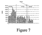
- FIG. 7 generally illustrates life cycle tests for jaw assemblies constructed in accordance with certain teachings of this disclosure.
- FIG. 8A generally illustrates an alternate embodiment of a sideplate with partial slots that extend in only one direction from pivot pin openings are provided as stress risers.
- FIG. 8B generally illustrates a sideview of the sideplate of FIG. 8A , taken along line A-A.
- FIG. 9 generally illustrates an alternate sideplate design where corner radii are adjusted and controlled to achieve the desired cycle life.
- FIG. 10A generally illustrates yet another alternate sideplate design where a fine blanking process is used to create pivot pin openings that are not round, but have small disruptions that act as stress risers.
- FIG. 10B generally illustrates a sideview of the sideplate of FIG. 10A .
- Applicants have conceived of and developed devices and methods that utilize sideplates associated with compression assembly, such as crimping tools, having stress risers formed into them, such stress risers including but not limited to slots, partial slots, and geometric disruptions, so as to ensure that the sideplate fails in a manner noticeable to a user of the compression assembly.
- the devices and methods include original equipment for use with compression assemblies, as well as retrofit equipment to modify existing compression assemblies and devices.
- the assembly 10 includes a crimping tool 12 and a jaw assembly 14 .
- the crimping tool 12 comprises a generally gun-shaped device that includes a hydraulically actuated piston assembly (not shown in FIG. 1 or 2 ) that is used to actuate the jaw assembly 14 in a manner known to of ordinary skill in the art.
- the crimping tool 12 can be battery or cord powered. Examples of known crimping tools that may be used to practice the subject matter of the present disclosure include the Model CT-400 and Model 320-E crimping tools available from Ridge Tool Company (Elyria, Ohio).
- the jaw assembly 14 includes first and second jaw members or arms 16 A and 16 B that are coupled together via first and second sideplates 18 A and 18 B (only sideplate 18 A is visible in FIGS. 1 and 2 ).
- the jaws 16 A and 16 B are coupled to the sideplates 18 A and 18 B through first and second pivot pins 20 A and 20 B positioned in pivot pin openings 21 A, 21 B, 21 C and 21 D defined by the sideplates 18 A and 18 B.
- the pivot pins are held in place through the use of retaining rings 22 A, 22 B, 22 C and 22 D). As reflected in FIG.
- the side plates 18 A and 18 B define an opening 24 for receiving a retaining pin 26 for coupling (e.g., rotatably coupling) the jaw assembly 14 to the crimping tool 12 as is illustrated in FIG. 2 .
- a spring assembly 19 (depicted in FIG. 4 ) can be used to bias the jaws open.
- the jaws may be constructed in accordance with the teachings of published United States Patent Application No. 20040154371, “Compression Tool Jaw Member” and/or United States Patent Application No. 20030046973, “Crimping Assembly”, which are hereby incorporated by reference.
- FIG. 3 generally illustrates a side cutaway view of the assembly 10 depicted in FIGS. 1 and 2 .
- the jaw assembly 14 defines at its peripheral end 15 an opening 34 that is sized and shaped to engage a crimp fitting and to result in a crimping of such fitting when the jaw assembly 14 is actuated.
- the crimping tool 12 includes a hydraulically actuated piston assembly 30 that includes rollers 32 A and 32 B.
- the hydraulically activated piston assembly 30 When the crimping tool 14 is activated, e.g., through the depression of a trigger or switch, the hydraulically activated piston assembly 30 will be moved towards the jaw assembly 14 along a path of travel (illustrated by the arrow) causing the rollers 32 A ad 32 B to engaged the distal end 17 of the jaws 16 A and 16 B, resulting in a closing of the jaws 14 A ad 14 B and, if a crimp fitting was positioned in opening 34 , a crimping of the fitting.
- a path of travel illustrated by the arrow
- failure of the jaws 16 A and 16 B typically results in a crack forming in the jaws and/or deformation of the jaws. In many instances failure of the jaws results in a crack or deformation that either prevents further use of the jaw assembly or that is readily visible to the user of the crimping assembly 10 . In such instances, the potential for an incomplete and improper crimp is typically avoided because the jaw assembly 14 cannot be used or the user of the crimping tool will observe the crack or deformation and thereafter have knowledge that the jaw assembly 14 cannot be relied upon to produce a complete crimp.
- undesirable, inferior or incomplete crimps are reduced or avoided through the use of side plates 18 A and 18 B that are specially constructed to fail in an obvious and visible way before any reasonably anticipated failures of the jaws 16 A and 16 B.
- the anticipated cycle life for the sideplates used in a jaw assembly constructed in accordance with certain teachings of this disclosure should be between about 50% and about 80% of the minimum reasonably anticipated cycle life for the jaw arms.
- the desired cycle life for the side plates would be between about 5,000 to about 8,000 cycles. Such a cycle life range would tend to ensure that the side plate always failed before the jaw arms failed, and would also tend to ensure that the jaw assembly had an appropriate cycle life.
- FIGS. 4 and 5A and 5 B One exemplary jaw assembly that achieves the above goal of a sideplate that will fail in an obvious and visible way prior to anticipate failures of the jaws 16 A and 16 B is depicted in FIGS. 4 and 5A and 5 B.
- the sideplates 18 A and 18 B are formed with engineered stress risers, in the form of sharp corner milled slots 40 A, 40 B, 40 C and 40 D, being located on one side (or face) of the sideplates.
- the dimensions and positioning of the milled slots 40 A- 40 D were selected to ensure that the side plates would crack or fail prior to anticipated fatigue failures of the jaw arms 16 A and 16 B.
- the side plates 18 A and 18 B are constructed from steel, such as fine blanked X 42 NiCrMo 4 , 6 mm thick steel material that is blanked to form the sideplate and then milled, using known milling techniques, to produce the slots 40 A- 40 D.
- steel such as fine blanked X 42 NiCrMo 4 , 6 mm thick steel material that is blanked to form the sideplate and then milled, using known milling techniques, to produce the slots 40 A- 40 D.
- Other materials and methods known to those of skill in the art can be used to produced sideplates 18 A and/or 18 B.
- sideplates 18 A and 18 B include but are not limited to hot working steels such as CrMoV, CoCrWV, NiCrMoV, NiCrTi, WCrV, and the like; cold working steels including X100 CrMoV; MnCrMo steels, such as 21 MnCrMo 4 Grade steel; stainless martensitic steels; stainless ferritic/Austenitic steels; stainless Austenitic steels; cobalt-based alloys; high-temperature Austenitic steels, and combinations thereof.
- the sideplates may be roughly 2.008′′ wide and 1.083′′ high.
- the milled slots 40 A- 40 D are positioned such that they cross the pivot pin openings. This is because it was discovered that, in the absence of stress risers, sideplate failures for jaw assemblies as depicted in FIGS. 4 and 5 typically occur when repeated cycling of the jaw assembly results in the development of a fatigue crack that initiates at the pivot pin opening and propagates (up or down) until the part ultimately fractures.
- milled slot stress risers 40 A- 40 D By positioning the milled slot stress risers 40 A- 40 D such that they partially or, as illustrated, completely, cross over the pivot pin openings, which is the region where cracks naturally tend to initiate, it is possible to control when and where the cracks begin and thus construct a side plate that will fail in a noticeable and visible way within a relatively narrow band of operating cycles, which is beneficial in ensuring that the sideplate will fail prior to any reasonably anticipated failure of the jaw arms 16 A and 16 B.
- FIG. 6 illustrates a side plate, with milled slots, that has failed. As may be noticed, the inclusion of the milled slots has resulted the failure producing a large and visible crack 45 .
- FIG. 7 generally illustrates life cycle tests for jaw assemblies constructed with differing sizes milled slots 40 A- 40 D. Specifically, FIG. 7 reflects life cycles for jaw assemblies having: (a) a slot 0.015′′ deep ⁇ 0.250′′ wide (labeled “0.015 Slot”); (b) a slot 0.030′′ deep ⁇ 0.276 wide (labeled “0.030 Slot”); (c) a slot 0.045′′ deep ⁇ 0.276 wide (labeled “0.045 Slot”); (d) a slot 0.060′′ deep ⁇ 0.276 wide (labeled “0.045 Slot”). In general, these slot sizes were selected based on commonly available milling tooling.
- the dimensions of the milled slots can have a significant impact on the life cycle characteristics of the side plate assembly.
- sideplates formed with the 0.015 Slot slots initially failed within a reasonably narrow range of 7,023 cycles to 7,661 cycles.
- the cycle life of the parts begin to increase and, ultimately, reach and exceed 16,000 cycles, which would not necessarily provide the desired degree of separation between the anticipated cycle life of the sideplate and the anticipate cycle life of the jaw arms. This increase in the anticipated cycle life of the sideplates suggested that the milling currently used to form the slots was wearing out.
- cycle life was within a desirable and relatively narrow range.
- the cycle life of the side plates increased as well. This attribute is not necessarily desirable from a manufacturing standpoint.
- slot dimensions and cycle life results reflected in FIG. 7 are exemplary only and reflect the life cycles for side plates having dimensions and material parameters similar to the side plate generally illustrated in FIGS. 4 , 5 A and 5 B. Sideplates having different overall dimensions, or different material compositions, will likely produce different cycle lifes for different slot dimensions. However, the process described above, of testing different dimensions and multiple side plates, may be used to determine the desirable slot dimensions for a side plate of given dimensions and material composition.
- milled slots discussed above are but one approach that can be taken to introduce stress risers in the sideplates to ensure that the sideplates experience a visibly noticeable failure prior to the anticipated failure of the jaw arms.
- Other approaches can accomplish the same result.
- One such alternate approach would be to adjust the softness of the material from which the sideplates are formed to ensure appropriate failure of the sideplates.
- Another approach would be to use slots (milled or otherwise) that are not the full slots described above, but are partial slots that extend in only in one direction from the pivot pin openings.
- FIGS. 8A and 8B showing partial slots 80 A and 80 B extending in only 1 direction outward from pivot pin openings 21 A and 21 B on a face of a sideplate.
- FIG. 9 generally illustrates an alternate sideplate design where the corner radii 90 A and 90 B are adjusted and controlled to achieve the desired cycle life.
- FIGS. 10A and 10B generally illustrate a design where a fine blanking process is used to create pivot pin openings that are not round, but rather have openings that are, in general, circular, but that have small geometric disruptions 92 A and 92 B that act as stress risers.
- Such geometric disruptions 92 A and 92 B while illustrated in FIG. 10A as being generally semi-circular in shape, can be of any appropriate shape desired in order to act as stress risers.
Landscapes
- Engineering & Computer Science (AREA)
- Mechanical Engineering (AREA)
- Manufacturing & Machinery (AREA)
- Hand Tools For Fitting Together And Separating, Or Other Hand Tools (AREA)
- Manufacturing Of Electrical Connectors (AREA)
- Amplifiers (AREA)
- Crushing And Grinding (AREA)
- Discharge Heating (AREA)
- Vehicle Body Suspensions (AREA)
- Portable Nailing Machines And Staplers (AREA)
- Gripping Jigs, Holding Jigs, And Positioning Jigs (AREA)
- Electrical Discharge Machining, Electrochemical Machining, And Combined Machining (AREA)
- Insertion Pins And Rivets (AREA)
Priority Applications (1)
| Application Number | Priority Date | Filing Date | Title |
|---|---|---|---|
| US11/575,039 US7578159B2 (en) | 2004-09-09 | 2005-09-09 | Controlled cycle-life jaw assembly |
Applications Claiming Priority (3)
| Application Number | Priority Date | Filing Date | Title |
|---|---|---|---|
| US60819104P | 2004-09-09 | 2004-09-09 | |
| US11/575,039 US7578159B2 (en) | 2004-09-09 | 2005-09-09 | Controlled cycle-life jaw assembly |
| PCT/US2005/031799 WO2006031548A2 (en) | 2004-09-09 | 2005-09-09 | Controlled cycle-life jaw assembly |
Publications (2)
| Publication Number | Publication Date |
|---|---|
| US20070214859A1 US20070214859A1 (en) | 2007-09-20 |
| US7578159B2 true US7578159B2 (en) | 2009-08-25 |
Family
ID=35533478
Family Applications (1)
| Application Number | Title | Priority Date | Filing Date |
|---|---|---|---|
| US11/575,039 Expired - Lifetime US7578159B2 (en) | 2004-09-09 | 2005-09-09 | Controlled cycle-life jaw assembly |
Country Status (10)
| Country | Link |
|---|---|
| US (1) | US7578159B2 (de) |
| EP (1) | EP1786598B1 (de) |
| JP (1) | JP2008512265A (de) |
| AT (1) | ATE501430T1 (de) |
| CA (1) | CA2578235C (de) |
| DE (1) | DE602005026821D1 (de) |
| ES (1) | ES2361920T3 (de) |
| RU (1) | RU2402416C2 (de) |
| TW (1) | TWI370045B (de) |
| WO (1) | WO2006031548A2 (de) |
Cited By (21)
| Publication number | Priority date | Publication date | Assignee | Title |
|---|---|---|---|---|
| US20110289998A1 (en) * | 2010-05-28 | 2011-12-01 | Link-tech (Tianjin) Metal Products Co., Ltd. | Crimping/cutting Working Head for Impact Wrench |
| US20140237797A1 (en) * | 2013-02-25 | 2014-08-28 | Designed Metal Connections, Inc. | Pinned Head Swage Tool |
| USD730140S1 (en) * | 2013-09-17 | 2015-05-26 | Cembre S.P.A. | Crimping, cutting, or punching tool |
| US9388885B2 (en) | 2013-03-15 | 2016-07-12 | Ideal Industries, Inc. | Multi-tool transmission and attachments for rotary tool |
| USD805365S1 (en) * | 2016-06-27 | 2017-12-19 | Milwaukee Electric Tool Corporation | Hydraulic tool |
| USD823088S1 (en) * | 2017-02-10 | 2018-07-17 | Hubbell Incorporated | Portable power tool with dieless tool head |
| USD830147S1 (en) * | 2017-02-10 | 2018-10-09 | Hubbell Incorporated | Dieless tool head for power tools |
| US10109971B2 (en) | 2016-04-14 | 2018-10-23 | Hubbell Incorporated | Portable dieless hand held power tools |
| USD835963S1 (en) * | 2016-12-16 | 2018-12-18 | Cembre S.P.A. | Crimping tool |
| US10226826B2 (en) | 2013-10-22 | 2019-03-12 | Milwaukee Electric Tool Corporation | Hydraulic power tool |
| USD845733S1 (en) * | 2017-09-29 | 2019-04-16 | Izumi Products Company | Portable battery operated oil hydraulic tool |
| USD845734S1 (en) * | 2017-09-29 | 2019-04-16 | Izumi Products Company | Portable battery operated oil hydraulic tool |
| USD894703S1 (en) | 2019-01-17 | 2020-09-01 | Hubbell Incorporated | Smart tool housing |
| US20210252581A1 (en) * | 2018-11-05 | 2021-08-19 | Cincinnati Incorporated | 3D Printed Tools And Associated Methods |
| DE102021204604A1 (de) | 2021-03-11 | 2022-09-15 | Ridge Tool Company | Presswerkzeugsystem mit variabler kraft |
| US11458607B2 (en) * | 2016-12-21 | 2022-10-04 | Von Arx Ag | Press device |
| US11473701B2 (en) * | 2018-05-03 | 2022-10-18 | Dasung Tech Co., Ltd. | Connecting device and pipe press-fit connecting apparatus using the same |
| US12224545B2 (en) | 2021-06-21 | 2025-02-11 | Milwaukee Electric Tool Corporation | Systems and methods for evaluating crimp applications |
| US12251802B2 (en) | 2021-03-11 | 2025-03-18 | Ridge Tool Company | Variable force press tool system |
| US12497988B2 (en) | 2015-05-06 | 2025-12-16 | Milwaukee Electric Tool Corporation | Hydraulic power tool |
| US12627107B2 (en) | 2021-08-11 | 2026-05-12 | Milwaukee Electric Tool Corporation | System and methods for determining crimp applications and reporting power tool usage |
Families Citing this family (12)
| Publication number | Priority date | Publication date | Assignee | Title |
|---|---|---|---|---|
| USD598259S1 (en) * | 2006-07-25 | 2009-08-18 | Emerson Electric Co. | Dual operation crimp and press jawset |
| DE102007006929A1 (de) * | 2007-02-05 | 2008-08-07 | REMS-WERK Christian Föll und Söhne GmbH & Co KG | Presszange |
| US20080289394A1 (en) * | 2007-05-23 | 2008-11-27 | Emerson Electric Co. | Compression jaw set with failure mode preventing reuse |
| DE102007061164B4 (de) * | 2007-12-17 | 2010-03-04 | Viega Gmbh & Co. Kg | Presswerkzeug mit bistabilem Spannungsmechanismus |
| DE202011103530U1 (de) * | 2011-07-21 | 2012-10-22 | Novopress Gmbh Pressen Und Presswerkzeuge & Co. Kg | Handgeführtes Presswerkzeug |
| ES2642388T3 (es) * | 2012-07-10 | 2017-11-16 | Gustav Klauke Gmbh | Herramienta de prensado |
| DE102014112869B3 (de) * | 2014-09-08 | 2016-01-07 | Viega Gmbh & Co. Kg | Presswerkzeug mit zuschaltbarem bistabilen Spannmechanismus |
| EP3246130B2 (de) | 2016-05-19 | 2022-02-09 | Geberit International AG | Pressvorrichtung |
| USD820060S1 (en) * | 2016-09-27 | 2018-06-12 | Milwaukee Electric Tool Corporation | Jaw assembly |
| US20180175575A1 (en) * | 2016-12-16 | 2018-06-21 | Ridge Tool Company | Tool heads and tool systems |
| US12172271B2 (en) * | 2021-07-22 | 2024-12-24 | Ojjo, Inc. | Portable crimping device for joining foundation components |
| CN120569274A (zh) * | 2023-01-18 | 2025-08-29 | 米沃奇电动工具公司 | 用于液压动力工具的工具头 |
Citations (8)
| Publication number | Priority date | Publication date | Assignee | Title |
|---|---|---|---|---|
| US3345856A (en) * | 1964-12-23 | 1967-10-10 | Amp Inc | Tool for crimping electrical connectors |
| US4641877A (en) * | 1985-09-18 | 1987-02-10 | Cooper Industries, Inc. | Lifting clamp cam wear indicator and method |
| US5279140A (en) * | 1992-05-18 | 1994-01-18 | Burndy Corporation | Tool handles having wear indication |
| US5611229A (en) * | 1995-02-13 | 1997-03-18 | Burndy Corporation | Abuse indicator for excessive handle loading |
| DE19918219C1 (de) | 1999-04-22 | 2001-01-18 | Dornier Gmbh | Lebensdauer-Indikator für hochbeanspruchte Leichtbau-Strukturen |
| US20030046973A1 (en) | 2001-09-11 | 2003-03-13 | Hamm James E. | Crimping assembly |
| US20040154371A1 (en) | 2003-02-12 | 2004-08-12 | Emerson Electric Co., A Missouri Corporation | Compression tool jawarm member |
| US7434440B2 (en) * | 2005-04-20 | 2008-10-14 | Murray Corporation | Heavy-duty PEX clamp installation tool |
Family Cites Families (1)
| Publication number | Priority date | Publication date | Assignee | Title |
|---|---|---|---|---|
| RU2146813C1 (ru) * | 1996-10-03 | 2000-03-20 | Институт механики Уфимского научного центра РАН | Способ оценки поврежденности деформируемого материала |
-
2005
- 2005-09-09 ES ES05812014T patent/ES2361920T3/es not_active Expired - Lifetime
- 2005-09-09 RU RU2007112692/02A patent/RU2402416C2/ru not_active IP Right Cessation
- 2005-09-09 DE DE602005026821T patent/DE602005026821D1/de not_active Expired - Lifetime
- 2005-09-09 JP JP2007531287A patent/JP2008512265A/ja active Pending
- 2005-09-09 TW TW094131237A patent/TWI370045B/zh not_active IP Right Cessation
- 2005-09-09 US US11/575,039 patent/US7578159B2/en not_active Expired - Lifetime
- 2005-09-09 WO PCT/US2005/031799 patent/WO2006031548A2/en not_active Ceased
- 2005-09-09 AT AT05812014T patent/ATE501430T1/de not_active IP Right Cessation
- 2005-09-09 CA CA2578235A patent/CA2578235C/en not_active Expired - Fee Related
- 2005-09-09 EP EP05812014A patent/EP1786598B1/de not_active Expired - Lifetime
Patent Citations (11)
| Publication number | Priority date | Publication date | Assignee | Title |
|---|---|---|---|---|
| US3345856A (en) * | 1964-12-23 | 1967-10-10 | Amp Inc | Tool for crimping electrical connectors |
| US4641877A (en) * | 1985-09-18 | 1987-02-10 | Cooper Industries, Inc. | Lifting clamp cam wear indicator and method |
| US5279140A (en) * | 1992-05-18 | 1994-01-18 | Burndy Corporation | Tool handles having wear indication |
| US5611229A (en) * | 1995-02-13 | 1997-03-18 | Burndy Corporation | Abuse indicator for excessive handle loading |
| DE19918219C1 (de) | 1999-04-22 | 2001-01-18 | Dornier Gmbh | Lebensdauer-Indikator für hochbeanspruchte Leichtbau-Strukturen |
| US6578430B1 (en) | 1999-04-22 | 2003-06-17 | Dornier Gmbh | Service life indicator for highly stressed light-weight structures |
| US20030046973A1 (en) | 2001-09-11 | 2003-03-13 | Hamm James E. | Crimping assembly |
| US7155955B2 (en) | 2001-09-11 | 2007-01-02 | Emerson Electric Co. | Crimping assembly |
| US20040154371A1 (en) | 2003-02-12 | 2004-08-12 | Emerson Electric Co., A Missouri Corporation | Compression tool jawarm member |
| US7000448B2 (en) | 2003-02-12 | 2006-02-21 | Emerson Electric Co. | Compression tool jawarm member |
| US7434440B2 (en) * | 2005-04-20 | 2008-10-14 | Murray Corporation | Heavy-duty PEX clamp installation tool |
Non-Patent Citations (1)
| Title |
|---|
| Search Report and Written Opinion for corresponding International Application No. PCT/US2005/031799. |
Cited By (25)
| Publication number | Priority date | Publication date | Assignee | Title |
|---|---|---|---|---|
| US8342001B2 (en) * | 2010-05-28 | 2013-01-01 | Link-tech (Tianjin) Metal Products Co., Ltd. | Crimping/cutting working head for impact wrench |
| US20110289998A1 (en) * | 2010-05-28 | 2011-12-01 | Link-tech (Tianjin) Metal Products Co., Ltd. | Crimping/cutting Working Head for Impact Wrench |
| US9737982B2 (en) * | 2013-02-25 | 2017-08-22 | Dmc Power, Inc. | Pinned head swage tool |
| US20140237797A1 (en) * | 2013-02-25 | 2014-08-28 | Designed Metal Connections, Inc. | Pinned Head Swage Tool |
| US9388885B2 (en) | 2013-03-15 | 2016-07-12 | Ideal Industries, Inc. | Multi-tool transmission and attachments for rotary tool |
| USD730140S1 (en) * | 2013-09-17 | 2015-05-26 | Cembre S.P.A. | Crimping, cutting, or punching tool |
| US10226826B2 (en) | 2013-10-22 | 2019-03-12 | Milwaukee Electric Tool Corporation | Hydraulic power tool |
| US11833597B2 (en) | 2013-10-22 | 2023-12-05 | Milwaukee Electric Tool Corporation | Hydraulic power tool |
| US12497988B2 (en) | 2015-05-06 | 2025-12-16 | Milwaukee Electric Tool Corporation | Hydraulic power tool |
| US10109971B2 (en) | 2016-04-14 | 2018-10-23 | Hubbell Incorporated | Portable dieless hand held power tools |
| US12244113B2 (en) | 2016-04-14 | 2025-03-04 | Hubbell Incorporated | Portable dieless hand held power tools |
| USD805365S1 (en) * | 2016-06-27 | 2017-12-19 | Milwaukee Electric Tool Corporation | Hydraulic tool |
| USD835963S1 (en) * | 2016-12-16 | 2018-12-18 | Cembre S.P.A. | Crimping tool |
| US11458607B2 (en) * | 2016-12-21 | 2022-10-04 | Von Arx Ag | Press device |
| USD823088S1 (en) * | 2017-02-10 | 2018-07-17 | Hubbell Incorporated | Portable power tool with dieless tool head |
| USD830147S1 (en) * | 2017-02-10 | 2018-10-09 | Hubbell Incorporated | Dieless tool head for power tools |
| USD845733S1 (en) * | 2017-09-29 | 2019-04-16 | Izumi Products Company | Portable battery operated oil hydraulic tool |
| USD845734S1 (en) * | 2017-09-29 | 2019-04-16 | Izumi Products Company | Portable battery operated oil hydraulic tool |
| US11473701B2 (en) * | 2018-05-03 | 2022-10-18 | Dasung Tech Co., Ltd. | Connecting device and pipe press-fit connecting apparatus using the same |
| US20210252581A1 (en) * | 2018-11-05 | 2021-08-19 | Cincinnati Incorporated | 3D Printed Tools And Associated Methods |
| USD894703S1 (en) | 2019-01-17 | 2020-09-01 | Hubbell Incorporated | Smart tool housing |
| DE102021204604A1 (de) | 2021-03-11 | 2022-09-15 | Ridge Tool Company | Presswerkzeugsystem mit variabler kraft |
| US12251802B2 (en) | 2021-03-11 | 2025-03-18 | Ridge Tool Company | Variable force press tool system |
| US12224545B2 (en) | 2021-06-21 | 2025-02-11 | Milwaukee Electric Tool Corporation | Systems and methods for evaluating crimp applications |
| US12627107B2 (en) | 2021-08-11 | 2026-05-12 | Milwaukee Electric Tool Corporation | System and methods for determining crimp applications and reporting power tool usage |
Also Published As
| Publication number | Publication date |
|---|---|
| TW200618953A (en) | 2006-06-16 |
| ES2361920T3 (es) | 2011-06-24 |
| WO2006031548A3 (en) | 2006-05-04 |
| EP1786598A2 (de) | 2007-05-23 |
| CA2578235A1 (en) | 2006-03-23 |
| CA2578235C (en) | 2010-08-10 |
| WO2006031548A9 (en) | 2006-06-22 |
| TWI370045B (en) | 2012-08-11 |
| RU2402416C2 (ru) | 2010-10-27 |
| JP2008512265A (ja) | 2008-04-24 |
| DE602005026821D1 (de) | 2011-04-21 |
| US20070214859A1 (en) | 2007-09-20 |
| ATE501430T1 (de) | 2011-03-15 |
| EP1786598B1 (de) | 2011-03-09 |
| RU2007112692A (ru) | 2008-11-10 |
| WO2006031548A2 (en) | 2006-03-23 |
Similar Documents
| Publication | Publication Date | Title |
|---|---|---|
| CA2578235C (en) | Controlled cycle-life jaw assembly | |
| EP1444061B1 (de) | Crimpanordnung | |
| US7434440B2 (en) | Heavy-duty PEX clamp installation tool | |
| US20110173810A1 (en) | Pneumatic compression tool and method of usingthe compression tool to attach a cable connector | |
| US20080216543A1 (en) | Enhanced Press Apparatus | |
| US7318334B2 (en) | Powered pipe flaring tool | |
| US7260975B2 (en) | Compression tool jawset | |
| JPH06341585A (ja) | 減圧部材を有するクイックカップリング要素 | |
| KR101077580B1 (ko) | 이동플랜지를 갖는 밸브 | |
| US6108883A (en) | Retaining ring removal tool | |
| US12253175B2 (en) | Metal bellows for downhole use | |
| US5611236A (en) | Crimping tool with means to keep jaws parallel | |
| WO2002076869A2 (en) | Chains | |
| AU2012350674A1 (en) | Method for producing a pipe connection by means of press fitting, and pressing tool | |
| JPH05205842A (ja) | 寿命指示可能な圧着工具及びその寿命指示方法 | |
| CN221696742U (zh) | 一种拔管钳子 |
Legal Events
| Date | Code | Title | Description |
|---|---|---|---|
| STCF | Information on status: patent grant |
Free format text: PATENTED CASE |
|
| FPAY | Fee payment |
Year of fee payment: 4 |
|
| FPAY | Fee payment |
Year of fee payment: 8 |
|
| MAFP | Maintenance fee payment |
Free format text: PAYMENT OF MAINTENANCE FEE, 12TH YEAR, LARGE ENTITY (ORIGINAL EVENT CODE: M1553); ENTITY STATUS OF PATENT OWNER: LARGE ENTITY Year of fee payment: 12 |