US7568620B2 - Imager kit with MICR head for hybrid printer - Google Patents
Imager kit with MICR head for hybrid printer Download PDFInfo
- Publication number
- US7568620B2 US7568620B2 US11/160,794 US16079405A US7568620B2 US 7568620 B2 US7568620 B2 US 7568620B2 US 16079405 A US16079405 A US 16079405A US 7568620 B2 US7568620 B2 US 7568620B2
- Authority
- US
- United States
- Prior art keywords
- imaging media
- imaging
- media
- printer
- path
- Prior art date
- Legal status (The legal status is an assumption and is not a legal conclusion. Google has not performed a legal analysis and makes no representation as to the accuracy of the status listed.)
- Expired - Fee Related, expires
Links
Images


Classifications
-
- B—PERFORMING OPERATIONS; TRANSPORTING
- B41—PRINTING; LINING MACHINES; TYPEWRITERS; STAMPS
- B41J—TYPEWRITERS; SELECTIVE PRINTING MECHANISMS, i.e. MECHANISMS PRINTING OTHERWISE THAN FROM A FORME; CORRECTION OF TYPOGRAPHICAL ERRORS
- B41J13/00—Devices or arrangements of selective printing mechanisms, e.g. ink-jet printers or thermal printers, specially adapted for supporting or handling copy material in short lengths, e.g. sheets
- B41J13/10—Sheet holders, retainers, movable guides, or stationary guides
- B41J13/12—Sheet holders, retainers, movable guides, or stationary guides specially adapted for small cards, envelopes, or the like, e.g. credit cards, cut visiting cards
-
- B—PERFORMING OPERATIONS; TRANSPORTING
- B41—PRINTING; LINING MACHINES; TYPEWRITERS; STAMPS
- B41J—TYPEWRITERS; SELECTIVE PRINTING MECHANISMS, i.e. MECHANISMS PRINTING OTHERWISE THAN FROM A FORME; CORRECTION OF TYPOGRAPHICAL ERRORS
- B41J11/00—Devices or arrangements of selective printing mechanisms, e.g. ink-jet printers or thermal printers, for supporting or handling copy material in sheet or web form
- B41J11/0095—Detecting means for copy material, e.g. for detecting or sensing presence of copy material or its leading or trailing end
-
- B—PERFORMING OPERATIONS; TRANSPORTING
- B41—PRINTING; LINING MACHINES; TYPEWRITERS; STAMPS
- B41J—TYPEWRITERS; SELECTIVE PRINTING MECHANISMS, i.e. MECHANISMS PRINTING OTHERWISE THAN FROM A FORME; CORRECTION OF TYPOGRAPHICAL ERRORS
- B41J11/00—Devices or arrangements of selective printing mechanisms, e.g. ink-jet printers or thermal printers, for supporting or handling copy material in sheet or web form
- B41J11/48—Apparatus for condensed record, tally strip, or like work using two or more papers, or sets of papers, e.g. devices for switching over from handling of copy material in sheet form to handling of copy material in continuous form and vice versa or point-of-sale printers comprising means for printing on continuous copy material, e.g. journal for tills, and on single sheets, e.g. cheques or receipts
- B41J11/50—Apparatus for condensed record, tally strip, or like work using two or more papers, or sets of papers, e.g. devices for switching over from handling of copy material in sheet form to handling of copy material in continuous form and vice versa or point-of-sale printers comprising means for printing on continuous copy material, e.g. journal for tills, and on single sheets, e.g. cheques or receipts in which two or more papers or sets are separately fed in the same direction towards the printing position
-
- B—PERFORMING OPERATIONS; TRANSPORTING
- B41—PRINTING; LINING MACHINES; TYPEWRITERS; STAMPS
- B41J—TYPEWRITERS; SELECTIVE PRINTING MECHANISMS, i.e. MECHANISMS PRINTING OTHERWISE THAN FROM A FORME; CORRECTION OF TYPOGRAPHICAL ERRORS
- B41J3/00—Typewriters or selective printing or marking mechanisms characterised by the purpose for which they are constructed
- B41J3/44—Typewriters or selective printing mechanisms having dual functions or combined with, or coupled to, apparatus performing other functions
Definitions
- the present invention generally relates to hybrid printers, such as printers that print text on media, such as a receipt, and also scan an image of media, such as a check.
- Check processing is fast progressing from methods that require transportation from the place of payment to the account holder's mailbox, including numerous intermediate physical handlings.
- the driving force is cost, since it is much less expensive to send electronic data than it is to move physical items. This transition has been on-going for several years and the latest inducement is in the Check 21 Act, which gives legal status to recreating a check from image data if paper is still required at any point to complete the journey.
- Transitioning to processing in digital form is based on acquisition of electronic equipment for this, and because this is a costly change and requires significant logistical and training support, it is occurring over a period of time, even within small stores and bank branches.
- a consideration in planning for document digitization is where that digitization should be done; and if that target is at the point of first presentment of (financial) documents whether to replace devices with new ones that already have the needed features or with devices that can be upgraded at the actual start-of-use time with the needed features.
- the present invention provides a hybrid printer having printing capabilities at its back end and imaging capabilities at its front end.
- a conventional receipt printer with a MICR read head has been modified by replacing its front cover with a cover having the same planform but that incorporates a pair of opposed imagers, a second MICR read head, and rollers for moving media therethrough.
- a printed circuit board embedded with the firmware needed to operate the imagers is plugged into the existing control board of the printer and is hard wired to the instructional hardware driving the imagers and MICR read head.
- Various combination of connector options can be included on the upgraded board and control board, such as RS232, USB, or Ethernet.
- the imager cover includes a media introduction point formed in its front surface, in addition to maintaining the traditional bottom and side/top media introduction points.
- the front introduction point accommodates media of varying thickness and rigidity, and passes the media presented therethrough directly past the imagers and second MICR read head.
- Media such as paper checks, plastic cards, credit card slips, and the like may be presented to the unit through this front presentment point. Due to the relatively straight path this presentment point follows, more rigid media, such as the plastic cards, can be effectively processed, as opposed to the curved path the media follows when presented through either the bottom or side/top presentment points.
- the top of the cover includes a pair of opposed imagers mounted in vertically spaced relation to one another and separated by a predetermined distance that is sufficient to accommodate media of varying thicknesses therebetween but that is not so great as to lose image quality of any media having an acceptable thickness.
- Two sets of vertically opposed rollers are positioned laterally adjacent to the outer edges of the two imagers for purposes of frictionally engaging the media and moving it through the imagers.
- a pair of media sensors are positioned adjacent the outer edges of the roller sets to sense the leading and trailing edges of the media as it passes through the imaging module, and communicate this positional information to the motors driving the rollers, thus ensuring the media will fully pass through the imager module at a desired rate of speed.
- the imager module is equipped with a MICR read head that is positioned on the opposite side of the media path as the MICR read head present in the base printer, thus providing the retrofit printer with the ability to read MICR code present on either side of the media.
- FIGS. 1A-1D are perspective views of a prior art hybrid transaction printer
- FIGS. 2A and 2B are both perspective views of the present invention taken along different orthogonal angles and with the scanner module cover open;
- FIG. 3 is a top plan view thereof
- FIG. 4 is a front elevation view thereof
- FIGS. 5A and 5B are opposite side elevation views thereof
- FIG. 6A-6C are cross-sectional side elevation views of the imaging module, and FIG. 6D is a bottom perspective view of the imaging module;
- FIG. 7 is a sectional view taken along section line ZZ-ZZ of FIG. 6C ;
- FIG. 8 is a schematic representation of the imaging module
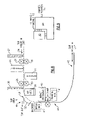
- FIG. 9 is a schematic representation of the printed circuit board structure associated with the present invention.
- FIGS. 2-8 a hybrid printer, designated generally by reference numeral 10 , generally comprising an imaging module 12 positioned at the printer's front end, and a receipt printer portion 14 positioned at the printer's rear end.
- Imaging module 12 is adapted to scan media, such as a check, and produce a digital image thereof that can be stored in memory and electronically transmitted for further processing or storage.
- Printer portion 14 is conventional in the transaction printer industry and is adapted to print text, graphics, or combinations of the two on media, such as receipt paper.
- Printer portion 14 is identical to the printer portion of the model number A776 hybrid printer manufactured by TPG, Inc. of Ithaca, N.Y.
- imaging module 12 comprises a cover assembly 16 hingedly interconnected to the body 18 of printer 10 .
- Assembly 16 serves as housing for an upper imager 20 for digitally scanning the upwardly facing surface of media passing through module 12 , a lower imager 22 for digitally scanning the downwardly facing surface of the media and that is positioned in laterally and vertically spaced relation to upper imager 20 when assembly 16 is closed relative to body 18 , a pair of vertically opposed media feed rollers 24 , 26 positioned adjacent the outwardly facing edge of imager 20 , a pair of vertically opposed media feed rollers 28 , 30 positioned adjacent the outwardly facing edge of imager 22 , a media senor 32 positioned outwardly adjacent vertically aligned roller pairs 24 , 26 at the inlet of the front slip path 34 , and a media sensor 36 positioned outwardly adjacent vertically adjacent roller pairs 28 , 30 adjacent the exit of slip path 34 .
- sensor 32 senses the presence of media when it is inserted in slip path 34 and sends an electrical signal to the motors driving rollers 24 and 28 , thereby actuating the motors for a predetermined period of time and causing the opposed roller sets to grasp and advance the media past imagers 20 and 22 and MICR readers 38 and 40 .
- Sensor 36 senses the presence of the media and, more importantly, the lack of media, thus determining when the media has full passed imagers 20 and 22 .
- sensor 36 sends an electrical signal to the motors driving rollers 24 and 28 that will result in the motors turning off, thereby stopping the rollers after a predetermined period of time after the signal has been sent.
- Imaging module 12 includes standard bottom entrance and side/top entrance slip paths 42 , 44 , respectively, and further includes front entrance slip path 34 .
- Slip paths 42 and 44 each require the media to travel through a curved path in order to be fully imaged and MICR scanned, but front load slip path 34 provides an essentially straight travel path for the media. Due to this relatively straight path, media that is more rigid than paper, such as plastic cards, can be processed through this path. Furthermore, because the relative thickness of more rigid media is generally greater than the traditional paper media, slip path 34 is of a dimension that accepts a range of media thicknesses without compromising the quality of the image captured by imagers 20 and 22 .
- cantilevered springs 45 and 47 are mounted at opposing ends of, and positioned vertically below, thereby exerting an upward bias force on roller 26
- cantilevered springs 49 and 51 are mounted at opposing ends of, and positioned vertically below, thereby exerting an upward bias force on roller 30 .
- Springs 45 , 47 , 49 , and 51 collectively permit rollers 26 and 30 to flex a sufficient amount to maintain frictionally engaged relation to media passing thereover.
- the spring constant associated with springs 45 , 47 , 49 , and 51 is sufficiently low, preferably about 4 pounds/inch, to prevent over-stressing the motor driving rollers 24 and 28 .
- a deflector assembly 50 In order to ensure that media passing through the side/top or bottom load slip paths do pass by imagers 20 and 22 , a deflector assembly 50 is provided.
- Deflector assembly 50 includes a curved media deflector body 52 that is mounted to the body of printer 10 for pivotal movement about an axis X-X that extends transverse to the longitudinal axis of the printer. Media that passes through the top/side and bottom load slip paths are directed by curved body 52 into the slip path 34 that will cause the media to become engaged by roller pairs 24 , 26 and 28 , 30 , and pass by imagers 20 and 22 , and MICR readers 38 , 40 .
- the firmware and circuitry associated with imaging module 12 is preferably contained on its own printed circuit board 42 , although it is possible to accommodate the firmware necessary to operate imaging module on the same PCB that contains the firmware and circuitry for driving receipt portion 14 .
- interconnecting PCB 42 to the printed circuit board 44 containing the printer's control circuitry via a conventional interconnect module in a mezzanine arrangement is preferred.
- PCBs 42 and 44 can contain any combination of RS232, Ethernet, and USB connectors.
- Imaging module 12 can be originally provided with printer 10 , or it may be retrofit into pre-existing printers that contain less functionality than that offered by module 12 .
- the hybrid printer model number A776 manufactured and sold by TPG, Inc. of Ithaca, N.Y., illustrated in FIGS. 1A-1D , identified by reference numeral 100 is identical to printer 10 except that its front cover 102 does not contain any imaging capabilities, nor a front loading slip path (and consequently does not have an imaging PCB since it does not perform imaging.) Instead, printer 100 contains the same printer portion 14 as contemplated by printer 10 , a cover 104 for a slip processing portion having a MICR reader 106 positioned adjacent the exit of the slip path.
- Imaging media may be processed through one of two available slip paths; either a bottom loading path 106 or a top/side path 108 .
- printer 10 adds the front loading slip path 34 which permits processing of more rigid imaging media due to its relatively straight travel path versus the curved paths through which the media must travel in order to be processed through printer 100 .
- module 12 /cover assembly 16 is simply substituted for cover 102 , PCB 42 is connected to PCB 44 , and cabling electrically interconnects imaging module 12 to PCB 42 . Because cover assembly 16 is virtually identical in scale to cover 102 and in the manner it hingedly connects to the body of printer 10 / 100 , no other structural modification is necessary to complete the retrofit. Ribbon cable or other common data transfer cabling is then extended between module 12 and PCB 42 to provide the necessary instruction to imagers 20 , 22 and other associated hardware in module 12 in a manner that is readily apparent to one skilled in the art.
Landscapes
- Accessory Devices And Overall Control Thereof (AREA)
- Printers Characterized By Their Purpose (AREA)
Abstract
Description
Claims (11)
Priority Applications (1)
| Application Number | Priority Date | Filing Date | Title |
|---|---|---|---|
| US11/160,794 US7568620B2 (en) | 2004-11-15 | 2005-07-08 | Imager kit with MICR head for hybrid printer |
Applications Claiming Priority (2)
| Application Number | Priority Date | Filing Date | Title |
|---|---|---|---|
| US62803904P | 2004-11-15 | 2004-11-15 | |
| US11/160,794 US7568620B2 (en) | 2004-11-15 | 2005-07-08 | Imager kit with MICR head for hybrid printer |
Publications (2)
| Publication Number | Publication Date |
|---|---|
| US20060102723A1 US20060102723A1 (en) | 2006-05-18 |
| US7568620B2 true US7568620B2 (en) | 2009-08-04 |
Family
ID=36385214
Family Applications (1)
| Application Number | Title | Priority Date | Filing Date |
|---|---|---|---|
| US11/160,794 Expired - Fee Related US7568620B2 (en) | 2004-11-15 | 2005-07-08 | Imager kit with MICR head for hybrid printer |
Country Status (1)
| Country | Link |
|---|---|
| US (1) | US7568620B2 (en) |
Families Citing this family (2)
| Publication number | Priority date | Publication date | Assignee | Title |
|---|---|---|---|---|
| ITTO20030042U1 (en) * | 2003-03-12 | 2004-09-13 | Tecnost Sistemi S P A | ELECTRONIC TERMINAL PROVIDED WITH A TOP COVER WITH A DISPLAY SCREEN. |
| JP5198942B2 (en) * | 2008-06-05 | 2013-05-15 | 日本電産サンキョー株式会社 | Information media processing device |
Citations (4)
| Publication number | Priority date | Publication date | Assignee | Title |
|---|---|---|---|---|
| US5808645A (en) * | 1992-11-25 | 1998-09-15 | Tektronix, Inc. | Removable applicator assembly for applying a liquid layer |
| US6123260A (en) * | 1998-09-17 | 2000-09-26 | Axiohm Transaction Solutions, Inc. | Flagging unverified checks comprising MICR indicia |
| US6126073A (en) * | 1998-08-07 | 2000-10-03 | Axiohm Transaction Solutions, Inc. | Point-of-sale MICR printing and reading |
| US7210630B2 (en) * | 2003-11-10 | 2007-05-01 | Seiko Epson Corporation | Image scanning apparatus and a hybrid processing apparatus incorporating the image scanning apparatus |
-
2005
- 2005-07-08 US US11/160,794 patent/US7568620B2/en not_active Expired - Fee Related
Patent Citations (4)
| Publication number | Priority date | Publication date | Assignee | Title |
|---|---|---|---|---|
| US5808645A (en) * | 1992-11-25 | 1998-09-15 | Tektronix, Inc. | Removable applicator assembly for applying a liquid layer |
| US6126073A (en) * | 1998-08-07 | 2000-10-03 | Axiohm Transaction Solutions, Inc. | Point-of-sale MICR printing and reading |
| US6123260A (en) * | 1998-09-17 | 2000-09-26 | Axiohm Transaction Solutions, Inc. | Flagging unverified checks comprising MICR indicia |
| US7210630B2 (en) * | 2003-11-10 | 2007-05-01 | Seiko Epson Corporation | Image scanning apparatus and a hybrid processing apparatus incorporating the image scanning apparatus |
Also Published As
| Publication number | Publication date |
|---|---|
| US20060102723A1 (en) | 2006-05-18 |
Similar Documents
| Publication | Publication Date | Title |
|---|---|---|
| US8018632B2 (en) | Scanner/imager | |
| EP0606959B1 (en) | Article depositing apparatus | |
| US5507491A (en) | Gaming terminal | |
| CA2047579A1 (en) | Table top image based document processing machine and methods of processing documents | |
| US9776428B2 (en) | Multi-purpose printer | |
| JP2003520715A (en) | Passport making system and method | |
| US20090159659A1 (en) | Methods of operating an image-based self-service check depositing terminal to provide enhanced check images and an apparatus therefor | |
| EP1062642A1 (en) | Teller scanner | |
| GB2417120A (en) | Universal card reader apparatus and method | |
| CN102131031A (en) | Optical reading device, control method for an optical reading device, and program | |
| CN107743639B (en) | Core module for automatic transaction machine and automatic transaction machine | |
| CN101987535B (en) | Transportation alignment device, control method for a transportation alignment device, and recording device | |
| US7568620B2 (en) | Imager kit with MICR head for hybrid printer | |
| US8186516B2 (en) | Document processing system having a turn-around loop with component repositioning | |
| CN102398785A (en) | Deposit book type issuing module and deposit book type processing device | |
| US6304796B1 (en) | Vending machine operated by a chip card | |
| EP0895181A3 (en) | ID Card image reader | |
| US7633605B1 (en) | Prism sensor and method of operating a prism sensor for a check processing module of a self-service check depositing terminal | |
| CN208077325U (en) | A kind of multi-functional double-screen intelligent touch cash register all-in-one machine | |
| US7182249B2 (en) | Apparatus and method for obtaining data from a document | |
| CN108257332A (en) | A kind of multi-functional double-screen intelligent touches cash register all-in-one machine | |
| US8098391B2 (en) | Document processing system having improved operational sequencing | |
| GB2131353A (en) | Cheque printing apparatus | |
| US20100019027A1 (en) | Methods of processing a last check of a bunch of checks deposited at a self-service terminal during a bunch-check deposit transaction | |
| CN218630889U (en) | Ticket scanning and identifying equipment |
Legal Events
| Date | Code | Title | Description |
|---|---|---|---|
| AS | Assignment |
Owner name: ATSI HOLDINGS, INC., NEW YORK Free format text: ASSIGNMENT OF ASSIGNORS INTEREST;ASSIGNORS:DELANEY, ROBERT;KOEPELE, JEFFREY;SMITH, MICHAEL;AND OTHERS;REEL/FRAME:017011/0894 Effective date: 20050913 |
|
| STCF | Information on status: patent grant |
Free format text: PATENTED CASE |
|
| CC | Certificate of correction | ||
| AS | Assignment |
Owner name: COGNITIVETPG, LLC, NEW YORK Free format text: ASSIGNMENT OF ASSIGNORS INTEREST;ASSIGNOR:ATSI HOLDINGS, INC.;REEL/FRAME:028830/0528 Effective date: 20120822 |
|
| AS | Assignment |
Owner name: TOMPKINS TRUST COMPANY, NEW YORK Free format text: SECURITY AGREEMENT;ASSIGNOR:COGNITIVETPG, LLC F/K/A CTPG OPERATING, LLC;REEL/FRAME:028840/0274 Effective date: 20120822 |
|
| AS | Assignment |
Owner name: COGNITIVETPG, LLC, NEW YORK Free format text: CHANGE OF NAME;ASSIGNOR:CTPG OPERATING, LLC;REEL/FRAME:028915/0020 Effective date: 20120822 Owner name: CTPG OPERATING, LLC, NEW YORK Free format text: ASSIGNMENT OF ASSIGNORS INTEREST;ASSIGNOR:COGNTIVE TPG, LLC;REEL/FRAME:028896/0971 Effective date: 20120822 |
|
| AS | Assignment |
Owner name: PINE STREET CAPITAL PARTNERS II, LP, NEW YORK Free format text: SECURITY AGREEMENT;ASSIGNOR:COGNITIVETPG, LLC;REEL/FRAME:028921/0225 Effective date: 20120822 |
|
| FPAY | Fee payment |
Year of fee payment: 4 |
|
| FPAY | Fee payment |
Year of fee payment: 8 |
|
| AS | Assignment |
Owner name: COGNITIVETPG, LLC, NEW YORK Free format text: RELEASE BY SECURED PARTY;ASSIGNOR:PINE STREET CAPITAL PARTNERS II, LP;REEL/FRAME:054052/0646 Effective date: 20201014 |
|
| FEPP | Fee payment procedure |
Free format text: MAINTENANCE FEE REMINDER MAILED (ORIGINAL EVENT CODE: REM.); ENTITY STATUS OF PATENT OWNER: SMALL ENTITY |
|
| LAPS | Lapse for failure to pay maintenance fees |
Free format text: PATENT EXPIRED FOR FAILURE TO PAY MAINTENANCE FEES (ORIGINAL EVENT CODE: EXP.); ENTITY STATUS OF PATENT OWNER: SMALL ENTITY |
|
| STCH | Information on status: patent discontinuation |
Free format text: PATENT EXPIRED DUE TO NONPAYMENT OF MAINTENANCE FEES UNDER 37 CFR 1.362 |
|
| FP | Lapsed due to failure to pay maintenance fee |
Effective date: 20210804 |