EP0606959B1 - Article depositing apparatus - Google Patents
Article depositing apparatus Download PDFInfo
- Publication number
- EP0606959B1 EP0606959B1 EP94200081A EP94200081A EP0606959B1 EP 0606959 B1 EP0606959 B1 EP 0606959B1 EP 94200081 A EP94200081 A EP 94200081A EP 94200081 A EP94200081 A EP 94200081A EP 0606959 B1 EP0606959 B1 EP 0606959B1
- Authority
- EP
- European Patent Office
- Prior art keywords
- deposit
- transport
- deposits
- processing device
- document
- Prior art date
- Legal status (The legal status is an assumption and is not a legal conclusion. Google has not performed a legal analysis and makes no representation as to the accuracy of the status listed.)
- Expired - Lifetime
Links
Images


Classifications
-
- G—PHYSICS
- G07—CHECKING-DEVICES
- G07F—COIN-FREED OR LIKE APPARATUS
- G07F19/00—Complete banking systems; Coded card-freed arrangements adapted for dispensing or receiving monies or the like and posting such transactions to existing accounts, e.g. automatic teller machines
- G07F19/20—Automatic teller machines [ATMs]
- G07F19/202—Depositing operations within ATMs
-
- B—PERFORMING OPERATIONS; TRANSPORTING
- B65—CONVEYING; PACKING; STORING; HANDLING THIN OR FILAMENTARY MATERIAL
- B65H—HANDLING THIN OR FILAMENTARY MATERIAL, e.g. SHEETS, WEBS, CABLES
- B65H29/00—Delivering or advancing articles from machines; Advancing articles to or into piles
- B65H29/58—Article switches or diverters
-
- G—PHYSICS
- G07—CHECKING-DEVICES
- G07D—HANDLING OF COINS OR VALUABLE PAPERS, e.g. TESTING, SORTING BY DENOMINATIONS, COUNTING, DISPENSING, CHANGING OR DEPOSITING
- G07D11/00—Devices accepting coins; Devices accepting, dispensing, sorting or counting valuable papers
- G07D11/009—Depositing devices
- G07D11/0096—Accepting paper currency or other valuables in containers, e.g. in code-marked envelopes
-
- G—PHYSICS
- G07—CHECKING-DEVICES
- G07D—HANDLING OF COINS OR VALUABLE PAPERS, e.g. TESTING, SORTING BY DENOMINATIONS, COUNTING, DISPENSING, CHANGING OR DEPOSITING
- G07D11/00—Devices accepting coins; Devices accepting, dispensing, sorting or counting valuable papers
- G07D11/50—Sorting or counting valuable papers
-
- G—PHYSICS
- G07—CHECKING-DEVICES
- G07D—HANDLING OF COINS OR VALUABLE PAPERS, e.g. TESTING, SORTING BY DENOMINATIONS, COUNTING, DISPENSING, CHANGING OR DEPOSITING
- G07D7/00—Testing specially adapted to determine the identity or genuineness of valuable papers or for segregating those which are unacceptable, e.g. banknotes that are alien to a currency
- G07D7/004—Testing specially adapted to determine the identity or genuineness of valuable papers or for segregating those which are unacceptable, e.g. banknotes that are alien to a currency using digital security elements, e.g. information coded on a magnetic thread or strip
-
- G—PHYSICS
- G07—CHECKING-DEVICES
- G07D—HANDLING OF COINS OR VALUABLE PAPERS, e.g. TESTING, SORTING BY DENOMINATIONS, COUNTING, DISPENSING, CHANGING OR DEPOSITING
- G07D7/00—Testing specially adapted to determine the identity or genuineness of valuable papers or for segregating those which are unacceptable, e.g. banknotes that are alien to a currency
- G07D7/04—Testing magnetic properties of the materials thereof, e.g. by detection of magnetic imprint
-
- B—PERFORMING OPERATIONS; TRANSPORTING
- B65—CONVEYING; PACKING; STORING; HANDLING THIN OR FILAMENTARY MATERIAL
- B65H—HANDLING THIN OR FILAMENTARY MATERIAL, e.g. SHEETS, WEBS, CABLES
- B65H2408/00—Specific machines
- B65H2408/10—Specific machines for handling sheet(s)
- B65H2408/11—Sorters or machines for sorting articles
- B65H2408/112—Sorters or machines for sorting articles with stationary location in space of the bins and in-feed member movable from bin to bin
- B65H2408/1121—Sorters or machines for sorting articles with stationary location in space of the bins and in-feed member movable from bin to bin pivoting in-feed member
Description
- The present invention relates generally to an article depositing apparatus, and more particularly to an apparatus for receiving, processing and sorting envelopes and single document deposits. The invention is particularly suitable for an unmanned operation of accepting a deposit or receiving payments into a bank or like establishment, in conjunction with conventionally known automatic teller machines (ATM) and will be described with particular reference thereto. It is understood, however, that the present invention has other broader applications, and may be used to receive utility bills, notes, or other single sheet documents in other business situations.
- Automatic teller machines (ATM's) are widely used by banks and like establishments to provide unmanned cash dispensing to customers.
- European patent application 0 430 679 discloses a sheet and envelope processing device comprising first and second transports, printers, path-controlling gate members, and different storages. A common entry slot receives envelopes and single sheets. Transports move deposit items along a common feed path to a printer. A sheet aligner aligns sheets with a read head. Envelopes are fed to one container, and sheets are directed to one of two further containers.
- Business transactions with ATM' s are typically initiated by a customer using actuating keys on the ATM after the customer's identification has been established by means of a magnetic card having a customer's identification number and other pertinent information encoded thereon. ATM's have become extremely popular with banking and other financial institutions and their customers as a quick and convenient method of dispensing cash.
- However, for depositing money into a bank, or for paying utilities or like bills at a bank, it is generally necessary for such transactions to be handled by a bank teller during normal business hours. The present invention overcomes this and other problems and provides an article depositing apparatus for the acceptance of both envelopes and single document deposits, which machine can align and duplex single document deposits, sort deposits by kind, apply identification information to each deposit, magnetically scan and read single document deposits, obtain an image of one or both sides of a single document deposit, and the machine being compact and suitable for use with conventional ATM's.
- According to the present invention there is provided a deposit processing module comprising a first transport having a first end for receiving envelopes and single document deposits and a second end from which the deposits are discharged, and a second transport operatively positioned for receiving and returning single document deposits to and from the first transport. Print means are provided for printing information onto each deposit, magnetic charge/read means are provided for charging and reading magnetic information and coded on the deposits and an imager is provided to obtain an image of one or both sides of the deposits. A gate mechanism associated with the second end of the first transport is movable between a first position wherein envelopes and single document deposits may be discharged from the module and a second position wherein single document deposits may be transferred between the first transport and the second transport.
- In accordance with another aspect of the present invention, there is provided a deposit processing device for receiving envelope deposits and single document deposits. The deposit processing device includes a deposit processing module having a deposit receiving end and a deposit discharge end. A first transport path extends from the deposit receiving end to the deposit discharge end and is dimensioned to receive envelope deposits or single document deposits. Printer means are disposed along the first transport path for printing information onto said envelope deposit or the single document deposit. A second transport path is provided adjacent the first transport path dimensioned to receive single document deposits. Magnetic scanning means are disposed along the second transport path for scanning a single document deposit for coded information thereon. Imager means are disposed along the second transport path for obtaining an image of a single deposit thereon. Conveyor means are provided for conveying envelope deposits and single document deposits along the first transport path and for conveying single document deposits along the second transport path. Gate means operatively connects the first transport path with the second transport path to permit single document deposits to be conveyed therebetween. The deposit processing device further includes a deposit storage module adjacent the deposit discharge end of the deposit processing module having a plurality of storage locations including at least one envelope storage location and at least one single document storage location. Means for moving the deposit processing module relative to the deposit storage module are provided to position the discharge end of the document processing module adjacent one of the storage locations together with means for duplexing single document deposits to permit scanning and imaging of both sides of a single document deposit.
- In accordance with another aspect of the present invention, there is provided a deposit processing module comprising a first transport having a first end for receiving envelope deposits and single document deposits and a second end from which the deposits are discharged. Printing means are disposed along the first transport for printing deposit information on the deposits. A second transport having an end positioned adjacent the second end of the first transport is provided for receiving and returning single document deposits to and from the first transport. A magnetic charge/read head is disposed along the second transport for charging and reading magnetic information on the single document deposits and an imager is disposed along the second transport for imaging one side of the single document deposit. A gate mechanism is associated with the second end of the first transport, the gate mechanism being movable between a first position wherein envelope deposits and single document deposits may be discharged from the processing module from the second end of the first transport and a second position wherein single document deposits may be transported between the first transport and the second transport.
- In accordance with yet another aspect of the present invention, there is provided a depository for receiving envelopes, checks, utility bills, or other sheet notes comprising a deposit storage module having a plurality of deposit storage locations therein and a deposit receiving module. The deposit receiving module includes a printer for printing deposit information on a deposit, a magnetic charge and read head for magnetically charging and reading coded information on a deposit and an imager for copying the surface of a deposit. The deposit receiving module has a receiving end for receiving deposits and a discharge end for discharging the deposits to the deposit storage module. Means are provided for pivoting the receiving module about a fixed axis among a number of positions corresponding to the deposit storage locations.
- In accordance with a still further aspect of the present invention, there is provided a deposit processing module comprised of an elongated platen having opposite facing elongated planar surfaces and an endless belt encircling the platen having a first belt run extending along one of the opposite facing elongated surfaces and a second belt run extending along the other of the opposite facing surface. Reversible drive means are provided for conveying the belt around the platen. A first plate means is disposed adjacent one of the opposite facing elongated surfaces in operative engagement with the first belt run to define a first transport. A second plate means is disposed adjacent the other of the opposite facing elongated planar surfaces in operative engagement with the second belt run to define a second transport. A gate member is provided at one end of the platen and being movable relative thereto, the gate member having a contoured surface positionable adjacent the belt for conveying deposits between the first transport and the second transport.
- In accordance with a still further aspect of the present invention, there is provided a deposit processing module having a deposit receiving end, a deposit discharge end, a first deposit transport path extending between the deposit receiving end and the deposit discharge end and a second deposit transport path having one end positioned adjacent the deposit discharge end. Printer means are provided for printing information onto a deposit, magnetic scanning means are provided for scanning a deposit for coded information thereon, and imager means are provided for obtaining an image of a deposit, the printer means, magnetic scanning means and the imager means being positioned along the first and second transport paths. Reversible conveyor means are provided for conveying a deposit along the first and second transport paths. A gate member is movable to a position wherein the first deposit transport path is connected to the second deposit transport path and means for pivoting the device about a fixed axis are provided to move the deposit discharge end to a plurality of locations.
- It is an object of the present invention to provide a deposit processing device for receiving envelopes and single document deposits.
- It is another object of the present invention to provide a deposit processing device as described above which can sort like documents and envelopes.
- Another object of the present invention is to provide a deposit processing device as described above which can apply transaction identification information onto the deposit in a configurable location.
- Another object of the present invention is to provide a deposit processing device as described above which can magnetically charge and scan a deposit for magnetically coded information thereon.
- Another object of the present invention is to provide a deposit processing device as described above which can scan a deposit and record the image on one or both sides thereof.
- A still further object of the present invention is to provide a deposit processing device as described above which can duplex a single document deposit.
- A still further object of the present invention is to provide a deposit processing device as described above which includes means for justifying a deposit along a registration edge. A still further object of the present invention is to provide a document processing device as described above which includes first and second linear transports which are generally parallel to each other and which together are angularly pivotable about a fixed axis.
- A still further objection of the present invention is to provide a deposit processing device as described above which is capable of sorting and storing deposits into a plurality of storage locations.
- A still further objection of the present invention is to provide a deposit processing device as described above which is capable of receiving deposits in other than a single orientation.
- A still further objection of the present invention is to provide a deposit processing device as described above which is compact in size and is separable to expose internal components for ease of serviceability.
- These and other objects and advantages will become apparent from the following description of a preferred embodiment taken together with the accompanying drawings.
- The invention may take physical form in certain parts and arrangement of parts, a preferred embodiment of which will be described in detail in the specification and illustrated in the accompanying drawings which form a part hereof and wherein:
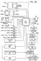
- FIG. 1 is an exploded perspective view of a deposit processing device illustrating a preferred embodiment of the present invention and showing a document processing module, a document storage module, and a main printed circuit board;
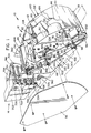
- FIG. 2 is an enlarged perspective view of the deposit processing module shown in FIG. 1;
- FIG. 3 is a schematic side elevational view of the deposit processing device shown in FIG. 1 showing one side of the device;
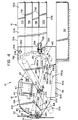
- FIG. 4 is a schematic side elevational view of the deposit processing device shown in FIG. 1 showing the other side of the device;
- FIG. 5 is a top, plan view of the deposit processing device shown in FIG. 1;
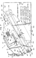
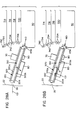
- FIG. 6 is an enlarged, partially broken away side elevational view of the deposit processing module and a portion of the deposit storage module showing the deposit processing module oriented to a top storage bin position;
- FIG. 7 is a side elevational view of the deposit processing module and deposit storage module showing an opposite view of that shown in FIG. 6;
- FIG. 8 is a top, plan view of the deposit processing module when positioned as shown in FIG. 7;
- FIG. 9 is a longitudinal sectional view taken along line 9-9 of FIG. 8;
- FIG. 10 is a plan view taken along line 10-10 of FIG. 9 showing portions of an upper transport;
- FIG. 11 is a plan view taken along line 11-11 of FIG. 9 showing portions of a lower transport;
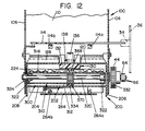
- FIG. 12 is a sectional view taken along line 12-12 of FIG. 9;
- FIG. 13 is a sectional view taken along line 13-13 of FIG. 9;
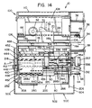
- FIG. 14 is an end view taken along line 14-14 of FIG. 9;
- FIG. 15 is an enlarged view showing the gate mechanism;
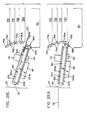
- FIG. 16 is a fragmentary, further enlarged view of FIG. 9 showing the gate mechanism in a first position;
- FIG. 17 is an enlarged view showing the gate mechanism in a position for conveying a document between the upper transport and the lower transport;
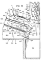
- FIG. 18 is a view similar to FIG. 16 showing the document processing module in a gate full "up" position from which a single document may be sent to a select location or be received therefrom;
- FIG. 19 is an end elevational view taken along line 19-19 of FIG. 18;
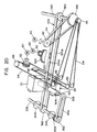
- FIG. 20 is a schematic, perspective view showing motor drive arrangement for moving components of the document processing module.
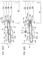
- FIGS. 21A-21C are schematic views of the deposit processing device shown in FIG. 1 illustrating successive positions of the deposit processing module when an envelope deposit is processed;
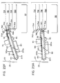
- FIGS. 22A-22F are schematic views of the deposit processing device shown in FIG. 1 illustrating successive positions of the deposit processing module when a single document deposit process;
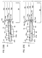
- FIGS. 23A-23D are schematic views of the deposit processing device as shown in FIG. 1, showing the successive positions of the deposit processing module when duplexing (i.e., inverting) a single document deposit;
- FIG. 24 is a perspective view of the deposit processing module showing the module opened for service;
- FIG. 25 is a block diagrammic representation of the electronic control system for the document processing device shown;
- FIG. 26 is a side elevational, sectional view of the receiving end of a document processing module according to the present invention, illustrating a modification to the document processing module to enable it to receive and process rigid or semi-rigid cards;
- FIG. 27 is a view taken along lines 27-27 of FIG. 26;
- FIGS. 28A and 28B are schematic views of the deposit processing module as shown in FIGS. 26 and 27, showing several positions of the deposit processing module when receiving a rigid or semi-rigid card; and
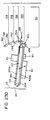
- FIGS. 29A and 29B are schematic views of a deposit processing module according to the present invention, together with an automatic document feeder for use therewith.
- Referring now to the drawings wherein the showing is for the purpose of illustrating a preferred embodiment of the invention only, and not for the purpose of limiting same, the drawings show a compact,
deposit processing apparatus 10 according to the present invention.Apparatus 10 is adapted to receive deposits such as envelopes containing currency or the like, and single document deposits, such as checks, utility bills, or other single sheet documents. In this respect, as used hereinafter, the term "deposit" shall generally refer to both envelopes and single sheet documents, the specific type of deposit being identified later in the specification when necessary to explain the operation ofapparatus 10.Apparatus 10 is preferably for use in conjunction with a conventional automatic teller machine (ATM), wherein access to the ATM is by means of a conventional magnetic identification card. As will be appreciated from a further reading of the specification, however,apparatus 10 has other uses and applications and may find advantageous application in situations not involving ATMS or ATMS requiring credit card access. -
Apparatus 10 would typically be situated adjacent ahousing facia 22 within a housing (not shown).Housing facia 22 includes aplate 24 having adeposit entry slot 26 which is accessible to a customer formed therein. In the drawings (see FIGS. 3 and 4),apparatus 10 is shown resting upon asupport surface 28 which is schematically illustrated. Anenvelope storage bin 30 is positioned to one side and belowapparatus 10 to receive and store envelope deposits which have been processed therethrough.Apparatus 10 is primarily comprised of adeposit processing module 12, and adeposit storage module 14 which is attachable thereto. - Referring to FIG. 3,
deposit processing module 12 is adapted to receive deposits throughdeposit receiving slot 26 and after processing same, to discharge the deposits intodeposit storage module 14 or theenvelope storage bin 30. Hereinafter, the end ofdeposit processing module 12 adjacent the housing facia shall be referred to as "the receiving end" or "front end" of the module, and the portion of the module adjacentdeposit storage module 14 shall be referred to as the "discharge end" or "back end" of the module.Apparatus 10 is positioned so that the receiving end thereof is adjacentdeposit entry slot 26. - Broadly stated,
deposit processing module 12 is generally comprised of three (3) sections or components, each of which is pivotally attached at one end to permit separation from each other for servicing as will be described in greater detail below. More specifically,deposit processing module 12 is generally comprised of anupper module section 100, alower module section 200, and a transport andgate assembly 300 which is positioned therebetween. - As shown in FIG. 2,
upper module 100 is generally comprised of asupport housing 102 having two spaced-apart,parallel sidewalls spacer bar 108 and acover plate 110 extend betweensidewalls Sidewalls transport motor 40, apivot motor 50, and ashuttle motor 60.Transport motor 40 andpivot motor 50 are mounted to sidewall 104 with their respective drive shafts extending therethrough.Shuttle motor 60 is mounted on an inward extendingpanel 112 cut fromsidewall 106. Adjacent tomotors circuit board 114 is provided and mounted on inward extending tabs (not shown) formed in thesidewalls circuit board 116 is provided at the discharge end ofupper module section 100. - Printed
circuit board sidewall 104, as best seen in FIGS. 1 and 2. Cover 110 (best illustrated in FIG. 9) is mounted to thesidewalls motors circuit board 114. Thelower end 118 ofcover plate 110 adjacent the receiving end ofdeposit processing module 12 is inturned toward the center thereof, as best seen in FIG. 9. - Forming part of
upper module section 100 is a floatingplate 120. Floatingplate 120 is generally U-shaped (as best seen in FIG. 13) and is dimensioned to be received betweensidewalls housing 102 ofupper module section 100. In the embodiment shown, floatingplate 120 is formed of a single metal sheet having the ends and sides bent to a desired configuration. In this respect, several components comprising the present invention, primarily the structural housings and support members, are preferably formed from single metal plates into complex shapes by cutting and bending such plates by conventionally known forming techniques. It is believed that the forming of such components is within the ability of those skilled in the art of metal forming and that the shapes of the components and how they may be formed is discernible from the drawings of the present invention. For this reason, and because the specific shapes of the structural components in and of themselves are not a primary aspect of the present invention, they shall not be described in great detail. Atransverse slot 122, shown in FIG. 8, is formed in floatingplate 120 to receive aprinter shuttle 70. In this respect, portions of floatingplate 120 along the sides ofslot 122 are bent upward to definerails 124 which act as guides and mounting surfaces forprinter shuttle 70. Anauxiliary mounting bracket 126, shown in FIG. 9, is attached to the upper surface of floatingplate 120 to provide an additional guide surface forprinter shuttle 70 and to confineprinter shuttle 70 within theslot 122. In this respect, the upper end of the auxiliary mounting bracket defines a generally L-shapedrail 126a along which printer shuttle may slide. - The receiving end of the floating
plate 120, i.e. the end of the floating plate adjacent thedeposit receiving slot 26, has an upturnedleading edge 128 which is formed to mesh with the inturnedlower end 118 ofcover plate 110. A centrally located,non-continuous rail 130 extends along the length of floatingplate 120.Rail 130 is generally comprised of two (2)rail sections slot 122.Rail sections plate 120, and are dimensioned to extend slightly below the lower surface ofprinter shuttle 70. The receiving end ofrail 130 is upturned and dimensioned to extend into slots (not shown) in theinturned end 118 ofcover plate 110. Anidle guide roller 136 extends through a slot (not shown) in the leading edge ofrail section 132.Guide roller 136 is mounted on aroller strut 138, shown in FIG. 12, which is mounted torail section 132 and is pivotable relative thereto. - Referring now to FIGS. 15 and 24,
rail section 134 at the discharge end of floatingplate 120 is best shown.Rail section 134 is comprised of afirst portion 134a which is fixedly secured to floatingplate 120 and asecond portion 134b which is formed to be slidably received byportion 134a.Rail portion 134b is attached to aflexible deflector 150 which is provided at the discharge end of floatingplate 120.Deflector 150 is preferably of a molded plastic construction and is shaped to be positioned on the upper surface of floatingplate 120 and extend downward over the end thereof. A flat coiledleaf spring 152 secured to floatingplate 120 biases the overextending end ofdeflector 150 downward to the position shown in FIG. 9. Arectangular pin 154 extends laterally outward from each side of deflector throughrectangular slots 156 formed insidewalls housing 102, as shown in FIGS. 2 and 6. In this respect,deflector 150 is movable withinsupport housing 102 onrectangular pins 154 sliding inslots 156 ofsidewalls deflector 150 is attached to railportion 134b such that the free end of floatingplate 120 is confined therebetween and slidable relative thereto. - As a result, the discharge end of floating
plate 120 is reciprocally movable, to a limited extent, towarddeposit storage module 14, i.e. to the right in FIG. 9, in addition to being movable in a vertical direction (i.e. by movement ofrectangular pins 154 in slots 156). The receiving end of floatingplate 120 is likewise movable relative tohousing 102. In this respect, the receiving end of floatingplate 120 is mounted tohousing 102 by means ofpins 162 projecting outward from the sides thereof which pins 162 extend throughinclined slots 164 insidewalls housing 102, as best seen in FIG. 7.Pins 162 which extend throughsidewalls helical spring 166 topins 168 which are fixedly mounted to the outer surfaces ofsidewalls pin 172 extends from the side of floatingplate 120past sidewall 104 and is connected byhelical spring 174 to apin 176 extending fromsidewall 104, as best seen in FIG. 6.Springs bias floating plate 120 downward to a normal position, as generally shown in FIG. 9. - Referring more specifically to
printer shuttle 70, a conventionally known print head is mounted withinprinter shuttle 70 for marking deposits with transaction code and/or customer information.Printer shuttle 70 is formed to include a plurality of aligned slots to operatively receiverails printer shuttle 70 is adapted to be freely movable alongrails printer shuttle 70 includes an outward extendingcam surface 72 which is positioned to engage apin 74 mounted to a plate onhousing 102.Pin 74 engagescam surface 72 whenprinter shuttle 70 is in a predetermined position withinslot 122. In this respect,cam surface 72 andpin 74 are dimensioned to cause theprinter shuttle 70 and floatingplate 120 to move upward relative to thelower module section 200 and transport andgate assembly 300 of thedocument processing module 12 as will be described in greater detail below during the discussion of the operation of the present invention. - Referring now to FIGS. 9, 11 and 13,
lower module section 200 ofdocument processing module 12 may be best seen.Lower module section 200 includes a generallyU-shaped housing 202 comprised of aflat plate 204 and two (2) downward extendingsidewalls flanges sidewalls plate 204. In the embodiment shown,flanges plate 204 and result invoids 216 being formed therein. Eachflange hub 218 which is in axial alignment with the other. The receiving end ofplate 204 is formed into a triangular shape, best seen in FIG. 9, having abarrier portion 222 and aguide portion 224.Guide portion 224 of theplate 204 includes serrated edges to mesh with other module components (best seen in FIG. 10) as will be discussed later. In this respect, the discharge end of theplate 204 is also serrated (as best seen in FIG. 11) and formed to operatively interact with other module components. - Two (2) generally
parallel transfer slots plate 204 and extend transverse to the longitudinal axis thereof.Slot 232 is dimensioned to a portion of ascanning imager 80.Scanning imager 80 is disposed below theplate 204 and between the sidewalls thereof with ascanning window 82 extending into theslot 232 and being flush with the upper surface of theplate 204. -
Slot 234 is provided to receive a magnetic ink character recognition (MICR)shuttle 90. To this end, portions of theplate 204 definingslot 234 are formed as spaced-apartrails 236 on whichMICR shuttle 90 is mounted and can slide.Rails 236 are dimensioned such that theMICR shuttle 90 is flush with the upper surface of theplate 204. As best seen in FIG. 11,rails 236 are formed to extend beyond thesidewall 206 of thehousing 202 to enable theMICR shuttle 90 to move sufficiently towardssidewall 206 such that the operative components of the MICR can magnetically charge or read information from a deposit position to that side of the plate. -
MICR shuttle 90 is comprised of a housing having slots dimensioned to receive therails 236. The operative portion of the MICR head is designated 240 in the drawings. Adjacent the MICR head on MICR shuttle 90 asensor 242 is provided. In the embodiment shown,sensor 242 is a retro-reflective sensor which is capable of detecting objects (i.e. sheet documents) passing thereover. BelowMICR shuttle 90, asolenoid 250, best seen in FIG. 11, is mounted belowplate 204.Solenoid 250 includes a reciprocallymovable pin 252 and a sensor 254 (shown schematically in FIG. 25) to monitor movement ofpin 252. Printedcircuit boards plate 204 adjacent the distal ends thereof as seen in the drawings. - Referring now to FIGS. 9-14, transport and
gate assembly 300 are best shown. The transport andgate assembly 300 is generally comprised of an elongated, hollow, box-like platen 310 and agate 410 which is pivotably mounted to the discharge end ofplaten 310. In the embodiment shown,platen 310 is formed from a generallyU-shaped bottom member 312 and a flattop member 314 which are secured to each other (by means not shown) to form a structure having a rectangular, box-like cross-section as best seen in FIG. 13. The distal ends ofplaten 310 are serrated to operatively mesh with the components located adjacent the ends thereof. Specifically, the receiving end ofplaten 310 meshes with the serrations formed onguide portion 224 ofplate 204, as shown in FIG. 10, and the discharge end of theplaten 310 meshes with serrations formed ongate 410, which is best seen in FIG. 10. - According to the present invention, a
drive shaft 320 extends through the receiving end of theplaten 310. As is best seen in FIG. 12,shaft 320 extends throughbushings 322 mounted through the sides of theU-shaped bottom member 312 so as to enableplaten 310 to be freely pivotally movable ondrive shaft 320. Driveshaft 320 extends beyond the sides ofplaten 310 and includes a pair ofouter bushings 324 which extend through thesidewalls housing 102 of theupper module section 100 and thehousing 202 of thelower module section 200. In this respect, theupper module section 100 and thelower module section 200 and theplaten 310 are all pivotally mounted ontodrive shaft 320, with thedrive shaft 320 being freely rotatable relative to each. - At one end of
shaft 320, atooth drive gear 332 is fixedly secured. Asecond tooth gear 334 is fixedly mounted near the middle ofdrive shaft 320.Gear 334 extends through slots formed in the upper and the lower surfaces ofplaten 310. - Referring now to the discharge end of
platen 310, asecond shaft 336 is provided, as shown in FIG. 14.Shaft 336 extends throughbushings 338 in the sides ofU-shaped member 312 to facilitate free rotation ofshaft 336 relative to platen 310. Atooth gear 342 is fixedly mounted toshaft 336 near the middle thereof to be in alignment withgear 334 ondrive shaft 320 . A pair ofconical rollers 344 are mounted onshaft 336 for rotation therewith and are positioned on opposite sides ofgear 342. A pair ofgears shaft 336. As shown in FIG. 10, atiming belt 356 connectsgear 352 to agear 358 on ashaft 362 which extends throughplaten 310. Aroller 364, which spans the width ofplaten 310, is mounted toshaft 362 for rotation therewith, as shown in FIG. 9.Shaft 362 androller 364 are positioned to be above the track ofMICR shuttle 90.Roller 364 extends slightly below the lower surface ofplaten 310 through a slot formed therein. - As best seen in FIG. 10, a
rail 368, which is aligned with and extends between thegears drive shaft 320 andshaft 336, projects from the upper surface ofplaten 310.Rail 368 is provided to support acontinuous transport belt 370 which encirclesplaten 310 lengthwise. In this respect,transport belt 370 is mounted ongears shafts Transport belt 370 has afirst belt run 370a acrossrail 368 on the upper surface ofplaten 310 and asecond belt run 370b along the lower surface ofplaten 310. Importantly, according to the present invention,shaft 336 androller 364 are positioned withinplaten 310 such that agap 380 is formed betweenbelt run 370b and the upper surface ofplate 204, as best seen in FIGS. 15 and 16.Gap 380 extends generally from the discharge end 18 ofplaten 310 to underMICR shuttle 90. BeyondMICR shuttle 90 to the receivingend 16 ofplaten 310,belt run 370b generally engages the upper surface ofplate 204. - Referring now to FIGS. 9, 10 and 15-17,
gate 410 is best illustrated.Gate 410 includes abarrier portion 412 which extends across the front ofplaten 310, as shown in FIG. 10, and a pair offlat arms 414 which extend along the sides of theplaten 310.Arms 414 are pivotally mounted toplaten 310 on pins for pivotable rotation relative thereto. In the embodiment shown,arms 414 are generally J-shaped and are secured tobarrier portion 412 by fasteners (not shown).Arms 414 project upward above theupper surface 310 of the platen and are joined tobarrier portion 412 such thatarms 414 extend thereabove. A temperedmetal rod 416 extends from the sides ofplaten 310 up over the upper surface ofbarrier portion 412 and acts as a spring tobias gate 410 in a downward direction. In this respect,arms 414 are formed to include alower edge 422, shown in FIG. 16, which acts as a stop againstshaft 336 to limitgate 410 in its downward direction to neutral position as shown in FIG. 16.Arms 414 likewise include asecond surface 424 which limits the upward movement ofgate 410 through engagement withshaft 336, as shown in FIG. 18.Barrier portion 412 has a generally flatupper surface 426 and is dimensioned such thatupper surface 426 is aligned with the upper surface ofplaten 310 when thegate 410 is in the neutral (home) position. As best seen in FIG. 10, the ends ofupper surface 426 are serrated to mesh with the edges ofplaten 310 and portions ofdeposit storage module 14. In addition, notches are formed ingate 410 to enable it to move without contacting theconical rollers 344 ortransport belt 370, as shown in the drawings. - When the
gate 410 is in its neutral position, as shown in FIGS. 9 and 16, anupper discharge slot 430 is defined between theupper surface 426 of thegate 410 and the lower surface ofdeflector 150. - Referring now to FIG. 15,
barrier portion 412 includes an arcuateinner surface 432 facing and encompassing the end ofplaten 310. Arcuate surfaces 432 merges with a flatlower surface 434. A generallyflat plate 436 is provided belowbarrier portion 412. In the embodiment shown,flat plate 436 is formed as part ofarms 414.Plate 436 is spaced fromlower surface 434 ofbarrier portion 412 and defines alower discharge slot 440 therewith. The ends oflower surface 434 and ofplate 436 are likewise serrated to mesh with the ends ofplaten 310 as well as components ondeposit storage module 14. As best seen in FIG. 16, a curved, outward facingsurface 442 is formed on the sidearm.Surface 442 faces towards thedeposit storage module 14 and is recessed slightly below the outer facing surface ofbarrier portion 412. Aninclined abutment surface 444 is formed at the upper portion ofbarrier portion 412 and merges withcurved surface 442. - As set forth above,
upper module section 100,lower module section 200, and the transport andgate assembly 300 which have heretofore been described separately, are pivotally mounted to driveshaft 320, which is best seen in FIG. 24.Upper module section 100, thelower module section 200, and the transport andgate assembly 300 are adapted to be joined together in operative engagement with each other. To this end, pairs oflatch elements 452, 454 (best seen in FIG. 6) are mounted on each side ofhousing 102 of theupper module section 100 to lock ontotabs 456 extending outward from the sides of thehousing 202 of thelower module section 200. Arelease bar 458 spans sidewalls 104, 106 ofhousing 102 ofupper module section 100 to connect thelatch elements 452 on each side thereof. - When united,
upper module section 100 andplaten 310 define a first transport therebetween, andlower section 200 andplaten 310 define a second transport therebetween, which is best seen in FIG. 9. More specifically, a first transport is defined between floatingplate 120 and the upper surface of theplaten 310. In this respect,transport belt 370 is operatively disposed againstrail 130 on floating plate 120 (i.e. envelopes and deposits) to capture documents therebetween and to transport the deposits alongrail section plate 120 between the receiving end and the discharge end ofdocument processing module 12. The second transport is defined by the lower surface ofplaten 310 andplate 204 ofhousing 202 of thelower module section 200. - In accordance with the present invention,
document processing module 12 is pivotally mounted to asupport frame 500, best seen in FIGS. 4, 6, 7 as 13. As shown in FIG. 13,support frame 500 is generally U-shaped and includes abottom wall 502 and two (2) sidewalls 504, 506 which are generally parallel to each other and spaced apart to receive thedocument processing module 12 therebetween.Document processing module 12 is pivotally mounted to supportframe 500 by means ofpins 512 extending throughsidewalls hubs 218 onhousing 202 ofbottom module section 200. In the embodiment shown, a major portion ofsidewall 504 is cut away to permit components ofdocument processing module 12, such as theend shafts gear block 522 having anarcuate rack gear 524 formed along the upper edge thereof is mounted tosidewall 504.Rack gear 524 is positioned to operatively engage apinion gear 52 on the shaft ofpivot motor 50.Adjacent gear block 522,sidewall 504 is formed to have acurved edge 532 having a plurality of notches andwindows 534 formed therethrough. -
Sidewall 506 of theU-shaped support frame 500 includes a plurality of apertures, designated 550a, 550b, 550c, 550d, 550e, 550f, and 550g which are arranged in an arcuate pattern, as best seen in FIG. 7.Apertures pin 252 ofsolenoid 250 so as to lockdeposit processing module 12 in one of a plurality of specific positions relative todeposit storage module 14, as will be described in greater detail below.Sidewalls notches 562 which are provided to locate and attachdocument storage module 14 to thedocument processing module 12. - Referring now to FIG. 20, a schematic view of the motor drive assemblies for the respective components of the
document processing module 12 is shown. In FIG. 20, thetransport motor 40, andpivot motor 50 andshuttle motor 60 are all schematically illustrated. According to the present invention, each motor is preferably a reversible stepping motor wherein the relative rotational position of it may be monitored, and thus the position of components driven thereby may be monitored. As indicated above,transport motor 40 is mounted to sidewall 104 ofupper module section 100 with its drive shaft extending therethrough. Agear 42 is mounted to the shaft oftransport motor 40 to drive atiming belt 44 which connectsgear 42 to gear 332 ondrive shaft 320. In this respect,transport motor 40 is operable to rotatedrive shaft 320 which in turn rotatesshaft 336 by means oftransport belt 370.Shaft 336 in turn drivesshaft 362, androller 364 thereon, by means oftiming belt 356. Thus,transport belt 370,conical rollers 344 androller 364 are simultaneously driven in the same direction bytransport motor 40. - As described above,
pivot motor 50 is operable to drivepinion gear 52 acrossrack 524 onplate 522, which in turn is operable to causedeposit processing module 12 to pivot about axis A onpins 512 and to angularly orientdeposit processing module 12 to one of theseveral positions -
Shuttle motor 60 is provided to reciprocally moveprinter shuttle 70 andMICR shuttle 90 across the width ofplaten 310. To this end, adrum 62 is mounted on the shaft ofmotor 60. The ends of acable 64 are mounted to drum 62 and wound around drum 62 to enablecable 64 to be wound or unwound in each direction depending upon the rotation ofshuttle motor 60. As shown in FIG. 20,cable 64 is wrapped over a system of pulleys, designated 66 in the drawings.Pulleys 66 are positioned to define form a continuous cable circuit, portions of which are adjacent, and run parallel to, the direction of movement ofprinter shuttle 70 andMICR shuttle 90. Idler pulleys 66 are mounted to driveshaft 320 to direct the cable therearound.Printer shuttle 70 andMICR shuttle 90 fixedly attached tocable 64 so as to move therewith. - To monitor the operation of
deposit processing module 12, as well as the position and configuration of deposits, a plurality of sensors are provided. According to the present invention, the sensors, and the circuitry associated therewith, have been arranged to facilitate ease of mounting and simple access thereto for maintenance purposes. In this respect, as set forth above,document processing module 12 includes a plurality of printedcircuit boards circuit boards document processing module 12, andcircuit board 114 being above andcircuit board 264 being belowplaten 310.Circuit board 264 includes a pair of light emitters, designated 264a, 264b in the drawings, as best shown in FIG. 11. As best shown in FIG. 9, openings inplate 204,platen 310 and inturned portion ofcover 110 permit a light beam to be directed fromemitters light receivers circuit board 114. In this respect,emitters receivers deposit processing module 12, three (3)light emitters lower circuit board 266 to direct individual beams of light through openings inplate 204,platen 310 and floatingplate 120 towardlight receivers circuit board 116. As shown in the drawings,emitters respective receivers platen 310.Light emitter 266a and itsrelated receiver 116a (not shown) is generally disposed along one edge ofplaten 310, as best seen in FIG. 11. - In addition to the above-identified emitters and receivers, additional sensors are provided to monitor the relative position of selected components of
deposit processing module 12. A generally U-shapedmodule rotation sensor 182, best seen in FIGS. 6 and 11, is provided to receivecurved edge 532 ofsidewall 504.Sensor 182 is operable to monitor the angular position ofdeposit processing module 12 by sensing the position ofwindows 534 with respect thereto. Conventionally known retro-reflective switches shown schematically and designated 184 and 186 in FIG. 25, are also preferably provided to sense a home position forprint shuttle 70 and forMICR shuttle 90 the home position beingadjacent sidewall 104 ofhousing 102. Asensor 188 is also preferably provided to sense a "gate up" position, i.e. whengate 410 is in its uppermost position. An additional sensor, designated 190 in FIG. 25, may also be provided to indicate whenlatch elements lower module sections gate assembly 300. Still further, a sensor, designated 192 in FIG. 25 is also preferably provided onprint shuttle 70 to sense the edge of a deposit for the purpose of locatingprint shuttle 70 relative to the deposit when information is to be printed thereon. - As indicated above,
light emitters light receivers circuit board Circuit boards motors printer shuttle 70,scanner imager 80 andMICR shuttle 90 by flex circuits (not shown) which can flex and bend asdeposit processing module 12, and various components thereof, move and operate. A portion of thecircuit boards sidewall 104 of thedocument processing module 12, as best seen in FIG. 1. These extending portions ofcircuit boards female connectors 34 on amaster circuit board 36.Master circuit board 36 is adapted to be mounted onspacer posts 38 extending outward from thedocument processing module 12, as best seen in FIG. 14, wherein themaster circuit board 36 and afemale connector 34 are shown in phantom. - Referring now to FIG. 25, a block diagrammic representation of the internal control system for the
document processing module 12 is shown. The physical operation ofdeposit processing module 12 are basically controlled by acentral processing unit 600 which is programmed to control operations of the various components ofdeposit processing module 12 by means of a program stored therein.Central processing unit 600 is connected to light emitters and receivers, and tomotors motors central processing unit 600 to monitor the relative position of the components, as well as to identify and monitor deposits placed therein.Central processing unit 600 is connected to the printer withinprinter shuttle 70 to provide instructions and information to be printed on a deposit.Scanner imager 80 is connected to the control processing unit (CPU) of the ATM to receive information in coded form for present transmission to an external database, such as a bank or similar financial institution, or for display to the ATM user on the CRT of the ATM, or for storage within memory of the CPU of the ATM for transmission at a later time.Central processing unit 600 is likewise connected to the MICR read head to receive information typically present on checks or other similar documents in coded text. A separatedecoding processing unit 610 is provided to decode and translate information obtained from a deposit to provide information identifiable tocentral processing unit 600 or to the external database. - Referring to FIGS. 4 and 5,
deposit storage module 14 is a rectangular, box-like structure having two spaced-apartparallel sidewalls top wall 706, and abottom wall 708. A plurality of spaced-apartshelves 712 extend betweensidewalls compartments Sidewall 704,top wall 706 andbottom wall 708 are formed so as to define an open corner for access tocompartments side panel 722 is spaced-apart and mounted tosidewall 702. Mounting lugs 724 extend fromsidewall 704 andpanel 722 and are positioned so as to be received within mountingnotches 562 onsupport frame 500 ofdeposit processing module 12. In this respect, mountinglugs 724 are provided to positiondeposit storage module 14 adjacent to depositprocessing module 12. To ensure accurate positioning, and to maintain accurate alignment between thedeposit storage module 14 anddeposit processing module 12, latchelements deposit storage module 14 in engagement withdeposit processing module 12. - In the embodiment shown, compartments 714, 716 and 718 are adapted to receive single document deposits from
deposit processing module 12, as shown in FIGS. 16 and 17. At the entrance to eachcompartments drive shaft 732 having a plurality ofdrive rollers 734 thereon is provided. Eachdrive shaft 732 extends betweensidewalls sidewall 702 andpanel 722. Agear 736 is mounted on the end of eachdrive shaft 732 and meshes with a secondintermediate gear 738 which is also confined betweenpanel 722 andsidewall 702.Gears 738 of eachcompartment gear 354 onshaft 336 ofplaten 310. In this respect,drive shaft 732 and driverollers 734 at the entrance tocompartments gear 354 onplaten 310 when platen 310 is aligned with a specific compartment.Idle rollers 742 mounted onshafts 744 are provided above and in mating engagement withdrive rollers 734.Deflectors 746 are provided betweendrive rollers 734 andidle rollers 742 to direct single document deposits into the associated compartment. The leading edges of the deflectors are serrated to mesh with the leading edges ofplaten 310. - According to one aspect of the present invention, the
lowermost compartment 720 is provided to enabledocument processing module 12 to duplex, i.e. to invert, single document deposits. To this end, a pair ofdrive shafts 752 are provided at the entrance tocompartment 720. Eachdrive shaft 752 includesdrive rollers 754 which mate withrollers 754 on theopposite drive shaft 752. Adrive gear 756 is provided at the end of eachshaft 752 and meshes with anintermediate gear 758 which is operable to engagegear 354 onshaft 336 ofplaten 310. - Referring now to FIGS. 15-18, a pair of
similar gate actuators 760 are mounted to the inner surfaces ofsidewalls Gate actuators 760 are mounted on a pair ofpins actuator 760. A biasingspring 766, having a predetermined spring force, urgesactuators 760 upward to a neutral position as shown in FIG. 15. As shown in the drawings, the upper slot is generally L-shaped, while the lower slot is straight. Eachactuator 760 is formed to have a pair of cam surfaces 772, 774 which are dimensioned to operatively engage and interact respectively with surfaces ongate 410 as will be described in greater detail below. In this respect, the slots ingate actuator 760 are configured such that when a downward force sufficient to overcome the biasing force ofspring 766 is exerted on theinclined cam surface 772 ofactuator 760,actuator 760 is forced downward and back (i.e. away from gate 410). In other words, one slot is inclined relative to the other slot to impart a slight rotation ofactuator 760 as it moves downwards. In addition, the L-shaped slot allowsactuator 760 to pivot backward aboutlower pin 764 when an upward force is exerted onlower cam surface 774, as will be described in greater detail below. - Referring now to the operation of the present invention,
apparatus 10 is preferably integrated as part of an automatic teller machine (ATM), wherein access toapparatus 10 may be accomplished by using conventionally known magnetically coded cards and utilizing keypads typically provided on the ATM to establish the identity of a customer. Authorization to useapparatus 10 may be obtained from a remote, external database, such as in a bank or other financial institution or from records maintained in memory within the central processing unit of the ATM. Importantly, system and hardware for accessingapparatus 10 in and of itself forms no part of the present invention. Moreover, it will be appreciated after understanding the operation of the present invention, thatapparatus 10, need not be part of an automatic teller machine (ATM), but may be used as a stand alone unit for other applications wherein access to the apparatus may be by means other than a magnetically encoded card. - With respect to the operation and use of
apparatus 10,deposit processing module 12 is adapted to operate in conjunction withdeposit storage module 14. Importantly, according to the present invention, specific operations ofdeposit processing module 12 are accomplished through interactive engagement between thegate 410 ofdocument processing module 12 andgate actuator 760 ondeposit storage module 14. In this respect, according to the present invention,deposit processing module 12 is pivotally movable about axis A to a plurality of positions relative todeposit storage module 14. In the embodiment shown,deposit processing module 12 is movable to seven (7) specifically defined positions relative todeposit storage module 14. In each position,deposit processing module 12 is locked into proper alignment withdeposit storage module 14 by means ofpin 252 onsolenoid 250 which projects into one of locatingapertures sidewall 506 ofsupport frame 500. In this respect, eachaperture support frame 500 represents a specific position ofdeposit processing module 12. For the purposes of illustrating operation of the present invention, in FIG. 7, eachaperture deposit processing module 12 in such position. - In general, the upper three (3)
apertures compartments deposit storage module 14,aperture 550a also being a "home position" fordeposit processing module 12.Aperture 550d represents a single document deposit "aligning position" and a position wherein single document deposit is conveyed between the upper transport and the lower transport.Aperture 550e represents a gate full "up" position and a position wherein single document deposits are conveyed from the lower transport to pinchrollers 754 and visa versa.Aperture 550f represents a "facia-aligned position". This position also allows document deposits to be sent or received frompinch rollers 754 to the upper transport.Aperture 550g represents an "envelope deposit position". FIG. 4 generally showsdeposit processing module 12 in the "facia-aligned position" for receiving a deposit, but also shows the range of movement ofdeposit processing module 12 by illustrating (in phantom) the positions oftransport belt 370, (i.e. platen 310) would assume whendocument processing module 12 is in its extreme, uppermost and lowermost positions. - As discussed previously,
apparatus 10 is adapted to receive envelope deposits which may contain currency or other documents of value, or single document deposits, such as checks, utility bills, or other notes of value. With the present invention, envelope deposits are handled differently than single document deposits. Accordingly, hereinafter "envelope deposits" shall be referred to as such and designated "ED" in the drawings, and deposits such as a check, utility bills, or some other single note of value shall be referred to as a "single document deposit" and designated "DD" in the drawings. - Referring now to the processing of a deposit, an authorization signal to allow access to
apparatus 10 is conveyed tocentral processing unit 600 from an external source. As indicated above, such signal may be received from an automatic teller machine (ATM), a bank, or other financial institution or some other source. Oncecentral processing unit 600 has received instructions to accept receipt of a deposit,central processing unit 600 instructspivot motor 50 to pivotdeposit processing module 12 about axis "A" to move same to the facia-aligned position, a position illustrated in FIG. 4. More specifically, pivotal movement ofdeposit processing module 12 is accomplished bypinion gear 52 being driven overarcuate rack gear 524. The relative position ofdeposit processing module 12 is monitored bycentral processing unit 600 based upon information received from steppingmotor 50 and from information received fromangular position sensor 182. With such information,central processing unit 600 may determine the relative location ofdeposit processing module 12 relative to deposit receivingslot 26 inhousing facia 22, as well as the relative position ofdeposit processing module 12 relative to depositstorage module 14. Whendeposit processing module 12 has pivoted to the "facia-aligned position",pivot motor 50 is stopped andsolenoid 250 is actuated such thatpin 252 thereon extends throughaperture 550f insupport housing 500. In this respect, deposit processing module is thus locked and aligned into a deposit receiving position, wherein the upper transport is aligned withdeposit receiving slot 26 throughhousing facia 22. - With
deposit processing module 12 in the "facia-aligned" position,central processing unit 600 initiatestransport motor 40, to initiate movement oftransport belt 370 in a direction to draw a deposit into the upper transport. - According to the present invention,
deposit processing module 12 is capable of identifying the type of deposit inserted therein, i.e. envelope deposit ED or single document deposit DD, by means of the optical sensors provided at the receiving end ofdeposit processing module 12. In this respect, as the leading end of the deposit enters the upper transport, it passes betweenlight emitters light receivers emitters receivers central processing unit 600 information as to the length, width and opacity ( which provides an indication of thickness) of the inserted deposit, with whichcentral processing unit 600 can identify whether the deposit is an envelope or single document based upon such information. - If an envelope deposit ED is detected,
transport motor 40 proceeds to transportdrive belt 370 to convey the envelope deposit ED to a position underprinter shuttle 70. Envelope deposit ED is drawn alongrail 130 of floatingplate 120 through frictional engagement withtransport belt 370. Importantly, becausetransport belt 370 andrail 130 on floatingplate 120 project above their respective surfaces, the upper transport has ample clearance on either side of transport belt 370 (i.e. between floatingplate 120 and platen 310) to facilitate the passage of envelope deposits ED which have lumps or enlargements to one side ofdrive belt 370. More importantly, becauseupper plate 120 effectively "floats" relative tohousing 102 ofupper module section 100, and may move away fromtransport belt 370, the upper transport can accommodate the passage of relatively thick envelope deposits ED. Importantly, floatingplate 120 not only moves upward away fromtransport belt 370 to receive thick deposits, it also shifts in the direction of movement of the thick deposit. In this respect,slots 164, through which pegs 162 extend, are slanted to allow floatingplate 120 to shift upward and in the direction of movement of the deposit. Such movement is facilitated because the dispensing end of floatingplate 120 may slide betweendeflector 150 andrail section 134a. -
Central processing unit 600 is programmed to position the envelope deposit belowprinter shuttle 70 by controllingtransport motor 40. Positioning envelope deposit ED belowprinter shuttle 70 can be accomplished by using the optical sensors, i.e.light emitters light receivers deposit processing module 12. With the envelope deposit ED positioned belowprinter shuttle 70,central processing unit 600 may activateshuttle motor 60 to positionprint head 70 to a desired location relative to the envelope deposit ED.Shuttle motor 60 is operable to moveprinter shuttle 70 transverse to the path of envelope deposit ED by wrappingcable 64 ontodrum 62. At this point, it should be noted that operation ofshuttle motor 60 also movesMICR shuttle 90 along its respective track. In this respect,printer shuttle 70 andMICR shuttle 90 move in tandem acrossplaten 310. A proximity sensor (not shown) adjacent one side ofdeposit processing module 12 is used to establish a "home position" for bothprinter shuttle 70 andMICR shuttle 90. - The
central processing unit 600 activatespivot motor 50 to rotatedeposit processing module 12 to the lowest position, i.e. the envelope deposit position as schematically illustrated in FIG. 21C. In this position,gate member 410 is in its neutral, lowermost position wherein theupper discharge slot 430 ofgate 410 is aligned with the first transport.Transport motor 40 is then actuated to drive the envelope deposit ED intoenvelope storage bin 30 for later retrieval by a bank employee or otherwise authorized individuals who can verify the content of the envelope deposit against the information entered by the user by retrieving the transaction information from memory ofcentral processing unit 600. Information is printed onto envelope deposit ED by passing envelope deposit ED beneath printer shuttle 70 (by means of transport belt 370) and simultaneously activating the print head withinprinter shuttle 70. The information printed onto envelope deposit ED would typically include a transaction number, the date and/or other coded information relating to the transaction and/or customer. As will be appreciated, the information printed on the envelope deposit ED is likewise maintained in memory or transferred to an external database for later retrieval. - Referring now to FIGS. 22A-22F, the processing of a single document deposit is illustrated. When a single document deposit such as a check or utility bill is inserted into the deposit receiving slot, it is drawn into the upper transport (the document processing module being in the facia aligned position) and conveyed toward the printer head. As the document deposit DD passes between
light emitters receivers platen 310 nearsidewall 104 ofhousing 102. - According to the present invention, "justification" or "alignment" of the document deposit DD is accomplished by first identifying the amount and direction of misalignment of document deposit DD. This is accomplished utilizing
light emitters receivers transport belt 370 past each corresponding pair oflight emitters receivers belt 370,central processing unit 600, by processing a trigonometric calculation can determine the amount and direction of misalignment of document deposit DD. Specifically, it can determine whether the leading edge of document deposit DD is away from side wall 104 (i.e. with the trailing edge being near side wall 104) or whether the trailing edge of document deposit DD is angled away fromside wall 104. Once the position of the document is established, "justification" or "alignment" of the document is generally accomplished by repeatedly transporting the misaligned end of document deposit DD, i.e. the end of the document outermost or furthest fromside wall 104 overconical rollers 344, shown in FIG. 10, between the upper and lower transport. - To this end,
document processing module 12 is moved to its "aligning position", best seen in FIG. 17 and schematically illustrated in FIG. 22C. As shown in FIG. 17, whendocument processing module 12 is in its "aligning position",cam surface 772 ofgate actuator 760 engages abuttingsurface 444 ofgate 410 andforces gate 410 upward into a position whereinarcuate deflecting surface 432 ofgate 410 is aligned with the upper surface oftransport belt 370. In this respect, biasingspring 766 onactuator 760 has sufficient spring force to counteract the biasing effect of temperedrods 416 which biasgate 410 to a downward position.Shuttle motor 60 is actuated to move printer shuttle 70 (together with the MICR shuttle 90) to a position where cam surface 72 onshuttle housing 70 rides up ontopin 74 extending fromsupport housing 102 to lift floatingplate 120 away from the single document deposit. -
Plate 120 is lifted away frombelt 370 to reduce the friction drive exerted bybelt 370 on document deposit DD. In this respect, in its normal position, i.e.plate 120 resting ontransport belt 370, a "high frictional drive" condition exists between the deposits andtransport belt 370 to drive deposits along the first transport. Withplate 120 lifted away fromtransport belt 370, a "low frictional drive" condition exists betweentransport belt 370 and the deposit. A "low frictional drive" is required to enableconical rollers 344 to shift a document deposit DD towardside wall 104. In this respect, conical rollers are designed to exert a relatively small lateral force, in the order of 1 ounce, on document deposit DD. This relatively small lateral force is necessary to avoid forcing and crumbling the document deposit DD intoside wall 104. Because the force ofconical rollers 344 is so small, the frictional force exerted on document deposit DD bytransport belt 370 must be removed to enable the document deposit DD to be moved byconical rollers 344. - If a document deposit DD is misaligned and the leading edge of the document deposit DD is disposed away from
side wall 104, document deposit DD is conveyed bytransport belt 370 to a position where the leading edge thereof is overconical roller 344. -
Transport motor 40 is then repeatedly driven, first in a forward direction and then in a reverse direction, to repeatedly convey the leading edge of single document deposit DD overconical rollers 344.Arcuate surface 432 ofgate 410 causes the leading edge to be guided around the end ofplaten 310 between the respective transports. As the leading edge of the single document deposit DD is reciprocally conveyed overconical rollers 344, the tapered surfaces ofsuch rollers 344 causes the leading edge of the document deposit DD to shift towards one side ofplaten 310. The optical sensor comprised oflight emitter 266a andlight receiver 116a which are positioned along the edge ofplaten 310, as best seen in FIG. 14, indicate when the single document deposit DD is aligned along the edge ofplaten 310. The document deposit is considered "aligned" or "registered" along the edge of the platen when eighty percent (80%) of the deposit is determined to be along the edge ofplaten 310. The inner surface ofside arm 414 ofgate 410 acts as a step and prevents the edge of the document deposit from shifting past the edge ofplaten 310. - If a document deposit DD is misaligned and the trailing edge of document deposit DD is oriented away from
side wall 104, the document deposit DD is conveyed from upper transport to the lower transport until such trailing edge is overconical roller 344. In this position, the leading edge of the document deposit DD would be captured betweenMICR shuttle 90 andtransport belt 370, and a major portion of the document would be withingap 380 which is defined betweentransport belt 370 andplate 204. Importantly,gap 380 creates a "low friction drive" condition such that when the trailing edge of document deposit DD is repeatedly driven overconical rollers 344, the trailing edge is forced into alignment byconical rollers 344 in a manner as described above. In this respect, the leading edge of the document deposit DD, which is captured betweenMICR shuttle 90 andtransport belt 370, experiences a "high frictional drive" condition which generally maintains the leading end of the document deposit in its original position as the trailing edge is conveyed into alignment byconical roller 344. - With respect to the aforementioned aligning process, the relative position of the document deposit during alignment is monitored by means of the optical sensors, i.e.
emitters receivers sensor 242 mounted to theMICR shuttle 90. - Once the document deposit is aligned along the edge of
platen 310, it is then conveyed from the upper transport to the lower transport as illustrated in FIG. 22D, again utilizingarcuate surface 432 ofgate 410 as a guide. As the document deposit DD is driven into the second transport, it passes overMICR shuttle 90 wherein the MICR head is energized to magnetize the document deposit wherein any code number thereon would be magnetized. In this respect, documents such as checks or utility bills typically include information set forth thereon in an ANSI standard bar code, wherein the bar code is printed with a magnetizable ink. Information typically found on commercial checks or utility bills would include: (1) institutional information regarding the institution issuing the check or bill, (2) an account number, and (3) a check number, bill number or statement number relating to the particular document. Larger institutions may also include (4) the amount of the check or bill, as part of the bar code information. As the document deposit passes over the MICR head, it also passes overwindow 82 ofscanner imager 80. As it does so, an image of the downward facing side of the document deposit is obtained and conveyed to central processing unit of the ATM via the scanner card for storage in memory, or is immediately transferred to external memory at the bank or financial institution. In this respect,transport belt 370 conveys the entire document deposit overimage scanner 80. When the leading edge of the document deposit has reached the optical sensors at the receiving end of lower transport,transport drive motor 40 is reversed to convey the document deposit back over the MICR head so that the above-identified magnetized, coded information may be removed therefrom. Generally, the coded information is typically provided at specific locations on a certain type of document.Central processing unit 600 is programmed to position theMICR shuttle 90 initially to a location wherein the coded information would be expected on the document deposit. In the event that the coded information is not found where expected,central processing unit 600 causestransport belt 370 to continually reverse itself to pass the document over theMICR shuttle 90, while at the same time, causingshuttle motor 60 to relocateMICR shuttle 90 along its rails to a position wherein the coded information might be found. In other words,central processing unit 600 is programmed to reposition the MICR head to search the document for the coded information. When the appropriate information has been obtained from the document, such information may be immediately transferred to the external memory of the financial institution, stored in memory by the central processing unit of the ATM to be downloaded to an external central database at a later time, or utilized in an immediate transaction with a customer. - Once the appropriate information is obtained from the document deposit, the document deposit is transported by
transport belt 370 back to the upper transport as illustrated in FIG. 22E, again usingarcuate surface 432 ofgate 410 as a guide. As the document deposit is returned to the upper transport, transaction information is printed thereon as it passes beneathprint shuttle 70. With the information obtained from the document deposit DD, and utilizing either preset instructions stored in memory, or instructions provided from an external source such as a central computer in a financial institution or the like,central processing unit 600 would select one of the threecompartments deposit storage module 12 into which document deposit DD is to be conveyed. - With the desired compartment identified by
central processing unit 600,pivot motor 50 is actuated to causedocument processing module 12 to be pivoted into alignment with the desired compartment. Asdocument processing module 12 moves from its "deposit aligning position, as shown in FIGS. 17 and 22E, toward one of the three (3) compartments 714, 716, 718, as shown in FIG. 22F (wherein the upper transport is aligned with compartment 716) and FIG. 16 (wherein the upper transport is aligned with compartment 714),gate 410 movespast gate actuator 760. In this respect, the upper end ofgate actuator 760 merely pivots aboutpin 764 out of the way of the lower portion ofgate 410 as it moves thereby. Importantly, asgate 410 moves away from, and out of engagement with,gate actuator 760,gate 410 is permitted to return to its normal (down) position wherein theupper discharge slot 430 ofgate 410 is in alignment with the upper transport. - Referring now to FIG. 16, the relative positions of
platen 310 andgate 410 ofdocument processing module 12 when in alignment withcompartment 714 ofdeposit storage module 14 are shown. In this position, the upper transport is in alignment withcompartment 714 such that a document deposit conveyed from the upper transport would be directed between thedrive rollers 734 andidle rollers 742. Importantly,intermediate gear 738 which meshes withgear 736 ondrive shaft 732 operatively engagesgear 354 on the end ofshaft 336 onplaten 310. Thus, astransport belt 370 is being driven bytransport motor 40 and simultaneously rotatesshaft 336 throughplaten 310 andgear 354 on end thereof which engages and drivesgear 738.Gear 738 in turn drivesrollers 734. The document deposit is thus caught betweenrotating drive rollers 734 andidle rollers 742, and conveyed intocompartment 714. When the trailing end of the document deposit has passed the optical sensors at the discharge end ofplaten 310,transport motor 40 continues to operate for a predetermined period of time to ensure that the document is conveyed entirely intocompartment 714. In this respect, a document deposit can be conveyed into any of the upper three (3) storage compartments in a similar manner. For example, FIG. 22F schematically illustrates a document deposit being driven intocompartment 716. As shown in the drawing,transport belt 370 is driven to convey the document deposit toward thedeposit storage module 14 whereindrive roller 734 at the entrance to the compartment withidle rollers 742 catch the leading edge of the document deposit and pull the document deposit into the compartment. - In accordance with another aspect of the present invention,
apparatus 10 includes means for "duplexing" or inverting a document deposit therein. Such feature is particularly applicable when a document deposit has been placed intodocument processing module 12 in an improper orientation, or merely to reorient a document deposit so as to enable both sides of the document deposit to be scanned or imaged by theMICR shuttle 90 or by theimage scanner 80. In this respect, FIGS. 23A-23D illustrate a procedure for "duplexing" a document withindocument processing module 12. In this respect, originally a document deposit would typically be processed discussed above. In this respect, the document deposit would first be "aligned" in a manner as previously described. It would then be conveyed from the upper transport (as shown in FIG. 23A) to the lower transport (as shown in FIG. 23B) to locate and obtain information from a bar code or magnetic code on the document deposit. In the event that the document has been inserted improperly into the document processing module, i.e. upside down, the MICR head would be unable to locate or read the bar code (which would be facing platen 310). If the MICR head is unable to locate or read a bar code,central processing unit 600 would initiate the "duplex" procedure. - To duplex the document deposit,
central processing unit 600 would initiate pivot drivemotor 50 to movedocument processing module 12 from its aligning position as shown in FIG. 17 to its "duplex position" as shown in FIG. 18. In this position,surface 772 ofgate actuator 760 has causedgate 410 to move to its uppermost position. In this respect,spring 766 which is attached togate actuator 760 has a spring force greater than the biasing force exerted byspring rods 416 ongate member 410, and therefore movesgate 410 upward wherein lower discharge slot 440 (i.e. the slot defined bylower surface 434 ofgate 410 and lower plate member 436) ofgate member 410 is in alignment withcompartment 720. In this position,gear 354 at the end ofshaft 336 operatively engagesintermediate gear 758 associated withupper drive shaft 752.Transport motor 40 is then initiated to causetransport belt 370 to convey the document deposit towarddrive rollers 754 at the entrance ofcompartment 720, as illustrated in FIG. 18. Importantly, the position of the trailing edge of the document deposit is monitored as it is being conveyed from the lower transport intolower compartment 720. In this respect,transport motor 40 is shut off once the document deposit has exitedlower discharge slot 440 ofgate 410. Importantly, the end of the document deposit is maintained betweendrive rollers 754 at the entrance tocompartment 720 as illustrated in FIG. 23C. - Once the document deposit has cleared the lower transport,
central processing unit 600 causespivot motor 50 to movedocument processing module 12 from its "duplex position" to the "facia-aligned. position", as illustrated in FIG. 9, wherein the upper transport is essentially aligned withlower compartment 720. In this respect,document processing module 12 is moved from its "duplex position" to the "facia-aligned position",gate actuator 760 is forced backward by abuttingsurface 444 ofgate member 410. In this respect,spring 766 whichbiases gate actuator 760 does not have sufficient strength to resist the overall movement ofdocument processing module 12. Accordingly, as described above,gate actuator 760 moves downward and shifts to the rear to enablegate 410 to move thereby whendocument processing module 12 moves to a lower position, i.e. the "facia-aligned position" or the "envelope deposit position". In the "facia-aligned position",document processing module 12 is oriented such thatdrive gear 354 onshaft 336 throughplaten 310 is in operative engagement withintermediate gear 758 connected to the lower set ofdrive rollers 754. In this position,transport motor 40 is actuated to cause the document deposit to be conveyed fromlower compartment 720 into the upper transport, as schematically illustrated in FIG. 23D. - With the document deposit conveyed back into the upper transport, the optical sensors on the discharge end of
document processing module 12 indicate when the trailing end of the document deposit has entered the upper transport.Central processing unit 600 then instructs thedocument processing module 12 to return to the "aligning position" wherein the document deposit may be transported from the upper transport to the lower transport in a manner as previously discussed. As will be appreciated, as the document deposit is conveyed from the upper transport to the lower transport, the side of the document which was originally facing away from image/scanner 80 andMICR shuttle 90 is now facing image/scanner 80 andMICR shuttle 90. In this position, it may be magnetically charged and read, or imaged in a manner as previously discussed. With the appropriate information obtained and after transaction information is printed thereon, the document deposit is then conveyed to one of the storage compartments 714, 716, 718, as discussed above. The invention as heretofore described, thus provides a single document processing apparatus capable of receiving envelope deposits, as well as document deposits such as checks, utility bills, or other valued notes. More importantly, an apparatus according to the present invention can scan, image and print onto one or both sides of a document deposit and accomplishes such scanning, imaging and printing, utilizing only one magnetic read head, one image/scanner and one print head. In this respect, the ability to duplex a document deposit reduces the necessity of duplicate components. - Moreover, the use of a bi-directional transport as well as a movable MICR head and print head enables the present invention to read account code information off documents inserted to the document processing module in any orientation. In addition, the movable shuttles, particularly the
MICR shuttle 90, enable variable print locations on deposited documents to be located and scanned. - With respect to the alignment mechanism, the use of conical shaped rollers and a bi-directional transport enables justification and straightening of documents against the registration edge for searching the location of coded information on deposits. Still further, by justifying the document around a curved path (i.e. between the upper transport and the lower transport) document rigidity is ensured to provide better transport and alignment of all types of sheet material.
- More importantly, the present invention accomplishes the foregoing by a relatively simple, compact mechanism. In this respect, a single common belt drive conveys documents through both the upper and lower transport. In addition, the pivotable document processing module enables storage of like documents in specific compartments and bins and simplifies transporting of documents by means of a gate which is movable by means of rotation of the document processing module. In addition to processing sheet document deposits DD and envelope deposits ED, a
document processing module 12 according to the present invention is also capable of processing rigid or semi-rigid cards such as a laminated driver's license or a plastic identification card. In this respect, the receiving end ofdocument processing module 12 may be modified to include arectangular slot 802, as seen in FIGS. 26 and 27.Slot 802 is formed inbarrier portion 222 ofplate 204 and is positioned to be in registry with the second transport, which is defined byplate 204 and the lower surface ofplaten 310. Referring now to FIGS. 28A and 28B,document processing module 12 is shown in its "envelope deposit position." In this position,slot 802 is in registry withdeposit entry slot 26 inhousing facia 22. A rigid or semi-rigid card, which is designated CD in the drawings, may be inserted into the second transport throughslots transport belt 370 andplate 204, and may be conveyed bytransport belt 370 over scanner/imager 80, where an image of the card CD may be obtained. In this respect,document processing module 12 may be used to copy and store identification information or authorization information from a rigid or semi-rigid card CD. Upon completion of the imaging, card CD would be returned to the user by reversingdrive belt 370. As will be appreciated, card CD could include magnetic information in coded form which could be read by the MICR head. Still further, according to the present invention, card CD may be transferred from the second transport to the upper transport to print thereon, in a manner similar to that described above to transfer sheet document during the duplexing procedure. - In this respect,
document processing module 12 would be moved to its "duplex position", as shown in FIG. 18.Transport motor 40 is then initiated to causetransport belt 370 to convey card CD betweendrive roller 754 at the entrance ofcompartment 720, the trailing edge of card CD being held betweendrive roller 754.Document processing module 12 is then moved to its "facia aligned position", as illustrated in FIG. 9, and card CD is conveyed into the first transport, where information may be printed onto the upward facing side of card CD. To return card CD to the customer, the sequence is reversed and card CD is conveyed from the first transport intobin 720 where its trailing edge is held byrollers 754, and then fromroller 754 into the second transport from where it may be returned to the customer. This present invention thus provides a document processing device which can receive and return an identification card or authorization card from a customer, and is capable of scanning such card for magnetic information, obtaining an image of such card and printing information onto such card. - Referring now to FIGS. 29A and 29B, a document feeding mechanism for picking a document from a stack and conveying the individual document to document
processing module 12 is schematically shown. In this respect, in some applications it may be desirable to utilize a document processing device according to the present invention to automatically process a stack of like documents. For example, a bank may wish to identify, image and sort checks drawn on accounts maintained at the bank. To this end, anautomatic document feeder 900 is shown.Document feeder 900 includes atray 902 for receiving a stack of documents DD to be processed. Apicker roller 904 is provided at the bottom oftray 902 to remove single documents from the bottom of the stack.Roller 904 includes agear 906, which meshes with anintermediate gear 908.Intermediate gear 908 is positioned to mesh with agear 910 provided onshaft 320 ofdocument processing module 12. - When
document module 12 is in its "facia-aligned position",gear 910 meshes withintermediate gear 908 as shown in FIG. 29A. Astransport belt 370 is driven,gear 910 drivesintermediate gear 908 which in turn drivesgear 906 onpicker roller 904.Picker roller 904 conveys a single document into first transport. Once the document is withindocument processing module 12,document processing module 12 is pivoted to another position such thatgear 910 disengagesintermediate gear 908. The document may then be processed in any preset manner and conveyed to a storage location as shown in FIG. 29B. - A deposit processing device as described above finds advantageous application with a conventional automated teller machine (ATM) for processing checks and/or utility bills. A conventional ATM would typically include a display monitor having a screen for displaying information to a customer, a card reader for reading information from an identification card, and a keypad for use by a customer for inputting information. A customer with an ATM card would access the ATM by inserting the card into the card reader and then utilizing the keypad to insert a personal identification code. Magnetic information on the ATM card would typically include the customer's name and an account number. Through a menu driven user interface, the customer may use the keypad (or touch designated areas on the screen) to input instructions to the ATM's central processor.
- According to the present invention, if a check is to be cashed by a customer, the scanner/imager of the deposit processing module would scan the face of the check in a manner as described above. The scanning process creates digital image data which would be conveyed to the ATM's central processor. According to a predetermined program, one or more select fields of information from the digital image data can be displayed on the monitor screen of the ATM. Specifically, in a check cashing procedure, the field showing the amount of the check is preferably displayed for the convenience of the customer. All or part of the check may then be cashed by the customer, with any remaining balance being credited to the customer's account.
- As indicated above, some institutional checks would include the amount of the check within the bar coded information thereon. In such situations, the central processor may compare the amount requested for withdrawal by the customer with the amount of the check and proceed with the currency dispensing if the amount requested by the customer is within the value of the check. In situations where the amount of the check is not within the bar coded information, a computer program may be provided wherein the digital image data information provided to the ATM is analyzed to determine the amount of the check. In this respect, the characters set forth in the "check amount" field would be analyzed to determine the amount of the check. Once the amount of the check is determined, the ATM's central processor again compares the amount requested by the customer with the amount of the check to determine whether sufficient funds exist therein to proceed with the check cashing procedure.
- A less complex program may be provided wherein the digital image data is analyzed to determine the number of characters preceding a delimiter character, i.e. the decimal point, in the identified "check amount" field. For example, the processor may determine that two numbers exist before the decimal point in the check amount field. With this information, the computer can recognize that the maximum amount of the check could be $99.99 and the minimum amount of the check would be $10.00. With this range of value, the central processor would analyze the amount requested by the customer. If the amount requested falls within the acceptable range, and if sufficient funds exist within the customer's account to overcome any possible shortfall in the amount of the check, the ATM may authorize cashing of the check for the amount requested by the customer. Thus, the ATM processor could be programmed to analyze general information and compare such information to a customer's account and base an authorization or denial of check cashing based upon programmed criteria.
- In addition to the foregoing advantages, the present invention, through its specific design, lends itself to easy maintenance by being pivotally hinged at one end wherein the operative components of the document processing module are accessible. In this respect, FIG. 24 shows how the upper and
lower module sections gate assembly 300. - The present invention thus provides a document processing module which is compact and extremely versatile. As indicated above, the present apparatus is capable of receiving envelope deposits, rigid or semi-rigid cards, and more importantly, may receive document deposits such as checks, utility bills, or other valued.notes. Importantly, with respect to single document deposits, the versatility of the present apparatus facilitates receipt of a wide range of varied types of document deposits and the ability of the document processing module to duplex the document facilitates financial transactions heretofore unavailable with existing devices.
- The present invention has been described with reference to a preferred embodiment. Other modifications and alterations will occur to those skilled in the art upon a reading and understanding of the present specification. It is intended that all such modifications and alterations be included insofar as they come within the scope of the appended claims or equivalents thereof.
Claims (29)
- A deposit processing device (10) for receiving deposits including envelope deposits and single document deposits comprising:
a deposit processing module (12) having a deposit receiving end and a deposit discharge end, said deposit processing module including:a first transport path (120,310) extending from said deposit receiving end to said deposit discharge end dimensioned to receive envelope deposits or single document deposits,printer means (70) disposed along said first transport path for printing information onto said envelope deposit or said single document deposit,a second transport path (204,310) adjacent said first transport path dimensioned to receive single document deposits,magnetic scanning means (90) for scanning a single document deposit for coded information thereon, conveyor means (370) for conveying envelope deposits and single document deposits along said first transport path and for conveying single document deposits along said second transport path,gate means (410,760) for operatively connecting said first transport path with said second transport path to permit single document deposits to be conveyed therebetween, anda deposit storage module (14) adjacent said deposit discharge end of said deposit processing module having a plurality of storage locations (714,716,718,720),
characterized in that said deposit processing module further comprises:imager means (80) disposed along said second transport path for obtaining an image of a single document deposit thereon,means (252,500a-500g) for moving said deposit processing module relative to said deposit storage module to position said discharge end of said document processing module adjacent one of said storage locations, andmeans (752,754,756,758,354,336) for duplexing single document deposits to permit scanning and imaging on both sides of a single document deposit. - A deposit processing device as defined in claim 1 wherein said deposit processing module is pivotally movable about a fixed axis among a plurality of positions relative to said deposit storage module.
- A deposit processing device as defined in claim 1 wherein said first and second transport paths are flat, linear paths and are generally parallel to each other.
- A deposit processing device as defined in claim 1 wherein said gate means includes a movable gate member positioned at said discharge end of said first transport, said gate member including an arcuate surface for directing single document deposits between first transport path and said second transport path.
- A deposit processing device as defined in claim 4 wherein said gate member has:a first position for conveying deposits between said deposit processing module and said deposit storage module,a second position for conveying a single document deposit between said first transport path and said second transport path, anda third position to facilitate duplexing a single document deposit.
- A deposit processing device as defined in claim 5 wherein said deposit storage module includes an actuator positioned to engage said gate member and move said gate member as said deposit processing module moves relative to said deposit storage module.
- A deposit processing device as defined in claim 1 wherein said printer means and said magnetic scanner means are movable relative to said first and second transport paths.
- A deposit processing device as defined in claim 1 further comprising sensing means for sensing the position of deposits along said first and second transport paths.
- A deposit processing device as defined in claim 1 wherein the deposit processing module includes:an elongated platen having opposite facing elongated planar surfaces,an endless belt encircling said platen having a first belt run extending along one of said opposite facing elongated surfaces and a second belt run extending along the other of said opposite facing surface,reversible drive means for moving said belt around said platen,first plate means adjacent said one of said opposite facing elongated surfaces in operative engagement with said first belt run to define said first transport path and being operable to move said envelope deposits and single document deposits along said platen, andsecond plate means adjacent said other of said opposite facing elongated planar surfaces in operative engagement with said second belt run to define said second transport path and being operable to move single document deposits along said platen.
- A deposit processing device as defined in claim 9 wherein the first plate means is yieldably mounted relative to said platen.
- A deposit processing device according to any one of claims 1-10, whereinthe magnetic scanning means includes a magnetic charge/read head (240) for charging and reading magnetic information on said single document deposits, andthe said gate means include a gate mechanism (760) associated with said second end of said first transport, said gate mechanism being movable between a first position wherein envelope deposits and single document deposits may be discharged from said processing module from said second end of said first transport and a second position wherein single document deposits may be transported between said first transport and said second transport,and that the imager (80) disposed along said second transport is capable to image one side of said single document deposits, andsaid magnetic charge/read head (240) is disposed along said second transport.
- A deposit processing device as defined in claim 11 wherein each of said transports defines a generally flat path, and the paths of said first and second transports are generally parallel to each other.
- A deposit processing device as defined in claim 11 wherein the deposit processing module is pivotally movable about a fixed axis between a plurality of angular positions.
- A deposit processing device as defined in claim 11 further comprising a plurality of deposit storage locations disposed adjacent said second end of said first transport, said deposit processing module is pivotally movable about a fixed axis between said plurality of deposit storage locations.
- A deposit processing device as defined in claim 11 further comprising aligning means for moving one edge of said single document deposit into registry with a registration edge.
- A deposit processing device as defined in claim 6 wherein said aligning means is comprised of conical discs which urge said single document deposits in a direction transverse to the path of said transports.
- A deposit processing device as defined in claim 11 further comprising means for duplexing a single document deposit.
- A deposit processing device as defined in claim 11 wherein the deposit processing module includes:an elongated platen having opposite facing elongated planar surfaces,an endless belt encircling said platen having a first belt run extending along one of said opposite facing elongated surfaces and a second belt run extending along the other of said opposite facing surface,reversible drive means for moving said belt around said platen,first plate means adjacent said one of said opposite facing elongated surfaces in operative engagement with said first belt run to define said first transport and being operable to move said envelope deposits and single document deposits along said platen, andsecond plate means adjacent said other of said opposite facing elongated planar surfaces in operative engagement with said second belt run to define said second transport and being operable to move single document deposits along said platen.
- A deposit processing device as defined in claim 18 wherein said magnetic charge/read head is transversely movable relative to the direction of said belt.
- A deposit processing device as defined in claim 18 wherein said printer is transversely movable relative to the direction of said belt.
- A deposit processing device as defined in claim 18 wherein said first plate means is yieldably mounted relative to said platen.
- A deposit processing device (10) according to any one of the preceding claims for processing envelopes, checks, utility bills, or other sheet notes comprising:
a deposit receiving module (12) having:the printer (70) for printing deposit information on a deposit,the magnetic charge and read head (240) for magnetically charging and reading coded information on a deposit,a receiving end for receiving deposits,a discharge end for discharging said deposits to the deposit storage module,characterized in that said deposit receiving
module further comprises:
means (50,52,524) for pivoting said receiving module (50,52,52') about a fixed axis (A) among a number of positions (550a-550g) corresponding to said deposit storage locations. - A deposit processing device according to any one of the previous claims comprising:sensor means (264a,264b,114a,114b,266a,266b, 116a,116b) for sensing the position, thickness, width and opacity of a document,transport means (370) for conveying the document past the sensor means, the magnetic scanning means, and the printer means, anda processing means (600) being connected to said sensor means, said magnetic scanning means, said printing means and said transport means for controlling their operation,characterized bymaging means (80) for obtaining digitized image data of said document, andmemory means for storing said digitized image data obtained by said image means, whereby said processing means is connected to said memory means, and thatsaid transport means (370) conveys documents past said imaging means.
- A deposit processing device as defined in claim 23 wherein said deposit processing device further comprises an ATM, connected to said processing means, including input means for inputting a user identification code and an input value, a display means, and a cash dispensing means.
- A deposit processing device as defined in claim 24, wherein said processing means identifies image data corresponding to a predetermined field of said digital image data stored in said memory means, and displays said identified image data on said display means.
- A deposit processing device as defined in claim 25, wherein said processing means computes a maximum value based upon a determination of a number of characters preceding a delimiter character in said identified image data.
- A deposit processing device as defined in claim 26 wherein said processing means compares an input value input by a user through said input means to said maximum value, in order to determine whether to dispense cash to said user through said cash dispensing means.
- A deposit processing device as defined in claim 26, wherein processing means searches a remote memory means, and retrieves user data corresponding to a user identification code input by said user through said input means.
- A deposit processing device as defined in claim 28 wherein said processing means determines whether to dispense cash to said user through said cash dispensing means based upon said maximum value, an input value input by a user through said input means, and said user data.
Applications Claiming Priority (2)
| Application Number | Priority Date | Filing Date | Title |
|---|---|---|---|
| US08/004,829 US5422467A (en) | 1993-01-15 | 1993-01-15 | Article depositing apparatus |
| US4829 | 1998-01-09 |
Publications (3)
| Publication Number | Publication Date |
|---|---|
| EP0606959A2 EP0606959A2 (en) | 1994-07-20 |
| EP0606959A3 EP0606959A3 (en) | 1994-09-21 |
| EP0606959B1 true EP0606959B1 (en) | 1997-12-03 |
Family
ID=21712729
Family Applications (1)
| Application Number | Title | Priority Date | Filing Date |
|---|---|---|---|
| EP94200081A Expired - Lifetime EP0606959B1 (en) | 1993-01-15 | 1994-01-14 | Article depositing apparatus |
Country Status (7)
| Country | Link |
|---|---|
| US (3) | US5422467A (en) |
| EP (1) | EP0606959B1 (en) |
| JP (1) | JPH0749976A (en) |
| AU (2) | AU664130B2 (en) |
| CA (1) | CA2113588C (en) |
| DE (1) | DE69407062T2 (en) |
| ES (1) | ES2113605T3 (en) |
Families Citing this family (152)
| Publication number | Priority date | Publication date | Assignee | Title |
|---|---|---|---|---|
| GB9313640D0 (en) * | 1993-07-01 | 1993-08-18 | Ncr Int Inc | Document transaction apparatus |
| GB9323709D0 (en) * | 1993-11-15 | 1994-01-05 | Ncr Int Inc | Depository apparatus for envelopes and single sheets |
| US5788348A (en) | 1994-03-15 | 1998-08-04 | Interbold | Automated teller machine with enhanced service access |
| US7152045B2 (en) * | 1994-11-28 | 2006-12-19 | Indivos Corporation | Tokenless identification system for authorization of electronic transactions and electronic transmissions |
| US6363164B1 (en) | 1996-05-13 | 2002-03-26 | Cummins-Allison Corp. | Automated document processing system using full image scanning |
| JP3126656B2 (en) * | 1996-02-29 | 2001-01-22 | ローレルバンクマシン株式会社 | Banknote handling machine |
| US8162125B1 (en) | 1996-05-29 | 2012-04-24 | Cummins-Allison Corp. | Apparatus and system for imaging currency bills and financial documents and method for using the same |
| US7187795B2 (en) | 2001-09-27 | 2007-03-06 | Cummins-Allison Corp. | Document processing system using full image scanning |
| US20050276458A1 (en) | 2004-05-25 | 2005-12-15 | Cummins-Allison Corp. | Automated document processing system and method using image scanning |
| US6290070B1 (en) | 1997-11-28 | 2001-09-18 | Diebold, Incorporated | Currency recycling automated banking machine |
| US6607081B2 (en) * | 1996-11-15 | 2003-08-19 | Diebold, Incorporated | Automated transaction machine system |
| US6273413B1 (en) * | 1997-11-28 | 2001-08-14 | Diebold, Incorporated | Automated banking machine with sheet directing apparatus |
| US7438219B1 (en) | 1999-11-30 | 2008-10-21 | Diebold Self-Service Systems Division Of Diebold, Incorporated | Check accepting and cash dispensing automated banking machine system and method |
| US5850075A (en) * | 1996-11-27 | 1998-12-15 | Interbold | Receipt transport and retrieval system for automated banking machine |
| US8478020B1 (en) | 1996-11-27 | 2013-07-02 | Cummins-Allison Corp. | Apparatus and system for imaging currency bills and financial documents and method for using the same |
| GB9624895D0 (en) * | 1996-11-29 | 1997-01-15 | Ncr Int Inc | Automatic teller machines |
| US6149056A (en) * | 1997-02-06 | 2000-11-21 | Mr. Payroll Corporation | Automatic check cashing using biometric identification verification |
| US6145738A (en) * | 1997-02-06 | 2000-11-14 | Mr. Payroll Corporation | Method and apparatus for automatic check cashing |
| JPH10217562A (en) * | 1997-02-06 | 1998-08-18 | Seiko Epson Corp | Paper end detection mechanism |
| US6012048A (en) * | 1997-05-30 | 2000-01-04 | Capital Security Systems, Inc. | Automated banking system for dispensing money orders, wire transfer and bill payment |
| US7653600B2 (en) | 1997-05-30 | 2010-01-26 | Capital Security Systems, Inc. | Automated document cashing system |
| US6023225A (en) * | 1997-07-17 | 2000-02-08 | Jeffrey V. Boley | Golf equipment inventory device |
| US5844483A (en) * | 1997-07-17 | 1998-12-01 | Boley; Jeffrey V. | Golf equipment inventory device |
| DE29812793U1 (en) * | 1997-09-17 | 1998-10-01 | Siemens Nixdorf Inf Syst | Device for evaluating machine-readable vouchers |
| EP1950712A1 (en) | 1997-11-28 | 2008-07-30 | Diebold, Incorporated | Automated banking machine with self auditing capabilities and system |
| US6170818B1 (en) | 1997-11-28 | 2001-01-09 | Diebold, Incorporated | Currency recycling automated banking machine media gate |
| WO1999028846A1 (en) | 1997-11-28 | 1999-06-10 | Diebold, Incorporated | Automated banking machine with self auditing capabilities and system |
| US6682068B1 (en) * | 1997-11-28 | 2004-01-27 | Diebold, Incorporated | Document alignment mechanism for currency recycling automated banking machine |
| US5974930A (en) * | 1998-01-06 | 1999-11-02 | Axiohm Transaction Solutions, Inc. | Miniature cutting apparatus for receipt printer |
| DE59810336D1 (en) * | 1998-01-23 | 2004-01-15 | Beb Ind Elektronik Ag Oberburg | Device for processing objects similar to securities |
| ES2212221T3 (en) | 1998-02-19 | 2004-07-16 | Innovative Technology Limited | CURRENCY PAPER VALIDATION DEVICE. |
| US7353988B1 (en) * | 1998-04-17 | 2008-04-08 | Diebold Self-Service Systems Division Of Diebold, Incorporated | Financial check with an electronic ink display |
| US6405929B1 (en) | 1998-05-29 | 2002-06-18 | Hand Held Products, Inc. | Material detection systems for security documents |
| US7900823B1 (en) | 1998-10-09 | 2011-03-08 | Diebold, Incorporated | Banking system controlled by data bearing records |
| US7533805B1 (en) | 1998-10-09 | 2009-05-19 | Diebold, Incorporated | Data bearing record based capture and correlation of user image data at a card reading banking system machine |
| US7389914B1 (en) | 1998-10-09 | 2008-06-24 | Diebold, Incorporated | Method of capturing and communicating correlated data of check transaction at card reading automated banking machine |
| US7229012B1 (en) * | 1998-10-09 | 2007-06-12 | Diebold, Incorporated | System and method for capturing and searching image data associated with transactions |
| GB9825510D0 (en) * | 1998-11-20 | 1999-01-13 | Ncr Int Inc | Self-service terminal |
| US7883005B2 (en) * | 1998-11-25 | 2011-02-08 | Diebold, Incorporated | Banking system controlled by data bearing records |
| US20040016796A1 (en) * | 1998-11-25 | 2004-01-29 | Diebold, Incorporated | Automated banking apparatus and method |
| US6761308B1 (en) * | 1998-11-25 | 2004-07-13 | Diebold, Incorporated | Automated merchant banking apparatus and method |
| DE19904536A1 (en) | 1999-02-04 | 2000-08-17 | Siemens Nixdorf Banking Syst | Process and arrangement for processing notes of value |
| JP2002538559A (en) * | 1999-03-03 | 2002-11-12 | キャッシュコード カンパニー インコーポレーテッド | Bill validator |
| US6142284A (en) * | 1999-03-22 | 2000-11-07 | Cashcode Company Inc. | Modular bill acceptor |
| US6167231A (en) * | 1999-03-31 | 2000-12-26 | Hewlett-Packard Company | Print recording apparatus having modular autoduplex mechanism |
| JP3744719B2 (en) * | 1999-04-15 | 2006-02-15 | 日立オムロンターミナルソリューションズ株式会社 | Medium issuing device and card issuing device |
| US7068832B1 (en) * | 1999-05-11 | 2006-06-27 | The Chase Manhattan Bank | Lockbox imaging system |
| US7067037B2 (en) | 1999-10-12 | 2006-06-27 | Com-Pac International, Inc | Modular reciprocating heat seal jaw assembly |
| US6863754B2 (en) * | 1999-10-12 | 2005-03-08 | Com-Pac International, Inc. | Apparatus and method for manufacturing reclosable bags utilizing zipper tape material |
| US6554185B1 (en) * | 1999-11-30 | 2003-04-29 | Diebold, Incorporated | Deposit accepting apparatus and system for automated banking machine |
| US6474548B1 (en) * | 1999-11-30 | 2002-11-05 | Diebold, Incorporated | Deposit accepting and storage apparatus and method for automated banking machine |
| DE10005752A1 (en) * | 2000-02-09 | 2001-08-23 | Schuler Pressen Gmbh & Co | Assembly for stacking large sheet plate components from a press station has direction change points to divert the pressed workpieces into two or more stacking belts in a start/stop feed to gripping transfer units or for manual removal |
| US8701857B2 (en) | 2000-02-11 | 2014-04-22 | Cummins-Allison Corp. | System and method for processing currency bills and tickets |
| US6985617B1 (en) * | 2000-04-20 | 2006-01-10 | Vectorsgi, Inc. | Method and system for emulating a check sorter |
| US6608274B1 (en) * | 2000-04-20 | 2003-08-19 | Sterling Commerce, Inc. | Method and system for online communication between a check sorter and a check processing system |
| GB2369914A (en) * | 2000-12-08 | 2002-06-12 | Ncr Int Inc | An automated teller machine network |
| GB0105509D0 (en) * | 2001-03-06 | 2001-04-25 | Rue De Int Ltd | Detector system and method |
| US20020152165A1 (en) * | 2001-04-12 | 2002-10-17 | International Business Machines Corporation | Method and apparatus for bill payments at an automatic teller machine |
| US20020152164A1 (en) * | 2001-04-12 | 2002-10-17 | International Business Machines Corporation | Method and apparatus for processing a check within a financial system |
| US20020152170A1 (en) * | 2001-04-12 | 2002-10-17 | International Business Machines Corporation | Method and apparatus for processing checks at an automatic teller machine for electronic transfer |
| US7555462B2 (en) * | 2001-04-12 | 2009-06-30 | International Business Machines Corporation | Method and apparatus for incorporating scanned checks into financial applications |
| US7177840B2 (en) | 2001-06-01 | 2007-02-13 | Vectorsgi, Inc. | Method and system for processing images for a check sorter |
| US7647275B2 (en) | 2001-07-05 | 2010-01-12 | Cummins-Allison Corp. | Automated payment system and method |
| CN1545675A (en) | 2001-08-21 | 2004-11-10 | ����ϲ�� | ATM deposit verification method |
| US8433123B1 (en) | 2001-09-27 | 2013-04-30 | Cummins-Allison Corp. | Apparatus and system for imaging currency bills and financial documents and method for using the same |
| US8437530B1 (en) | 2001-09-27 | 2013-05-07 | Cummins-Allison Corp. | Apparatus and system for imaging currency bills and financial documents and method for using the same |
| US8944234B1 (en) | 2001-09-27 | 2015-02-03 | Cummins-Allison Corp. | Apparatus and system for imaging currency bills and financial documents and method for using the same |
| US8428332B1 (en) | 2001-09-27 | 2013-04-23 | Cummins-Allison Corp. | Apparatus and system for imaging currency bills and financial documents and method for using the same |
| US8437529B1 (en) | 2001-09-27 | 2013-05-07 | Cummins-Allison Corp. | Apparatus and system for imaging currency bills and financial documents and method for using the same |
| GB0130480D0 (en) * | 2001-12-20 | 2002-02-06 | Ncr Int Inc | Self service terminal |
| US8171567B1 (en) | 2002-09-04 | 2012-05-01 | Tracer Detection Technology Corp. | Authentication method and system |
| US8627939B1 (en) | 2002-09-25 | 2014-01-14 | Cummins-Allison Corp. | Apparatus and system for imaging currency bills and financial documents and method for using the same |
| US8225989B1 (en) * | 2002-11-25 | 2012-07-24 | Diebold Self-Service Systems Division Of Diebold, Incorporated | Banking apparatus controlled responsive to data bearing records |
| US8453924B1 (en) * | 2002-11-25 | 2013-06-04 | Diebold Self-Service Systems Division Of Diebold, Incorporated | Banking apparatus controlled responsive to data bearing records |
| ITTO20030032U1 (en) * | 2003-02-27 | 2004-08-28 | Panini Spa | SCANNER APPARATUS FOR SCANNING BANK CHECKS. |
| CN101425199B (en) * | 2003-03-10 | 2012-12-19 | 迪布尔特有限公司 | Cash dispensing automated banking machine deposit accepting system and method |
| US20050097046A1 (en) | 2003-10-30 | 2005-05-05 | Singfield Joy S. | Wireless electronic check deposit scanning and cashing machine with web-based online account cash management computer application system |
| DE202004020440U1 (en) * | 2003-12-12 | 2005-06-09 | Wincor Nixdorf International Gmbh | Value ticket machine |
| US7205894B1 (en) | 2004-06-22 | 2007-04-17 | Savage Paul A | Missing golf club reminder and wireless golf bag alarm system |
| GB2416903A (en) * | 2004-07-29 | 2006-02-08 | Itautec Philco S A | Self-service deposit equipment for banking |
| GB0427693D0 (en) * | 2004-12-17 | 2005-01-19 | Ncr Int Inc | An automated teller machine |
| US7651083B2 (en) | 2006-09-21 | 2010-01-26 | Digital Check Corporation | Conveying apparatus and method |
| EP2076459A2 (en) * | 2006-10-18 | 2009-07-08 | Talaris Holdings Limited | Document handling apparatus |
| US8708227B1 (en) | 2006-10-31 | 2014-04-29 | United Services Automobile Association (Usaa) | Systems and methods for remote deposit of checks |
| US7873200B1 (en) | 2006-10-31 | 2011-01-18 | United Services Automobile Association (Usaa) | Systems and methods for remote deposit of checks |
| US7876949B1 (en) | 2006-10-31 | 2011-01-25 | United Services Automobile Association | Systems and methods for remote deposit of checks |
| US8351677B1 (en) | 2006-10-31 | 2013-01-08 | United Services Automobile Association (Usaa) | Systems and methods for remote deposit of checks |
| US8799147B1 (en) | 2006-10-31 | 2014-08-05 | United Services Automobile Association (Usaa) | Systems and methods for remote deposit of negotiable instruments with non-payee institutions |
| US7885451B1 (en) | 2006-10-31 | 2011-02-08 | United Services Automobile Association (Usaa) | Systems and methods for displaying negotiable instruments derived from various sources |
| JP5089138B2 (en) * | 2006-11-09 | 2012-12-05 | 日立オムロンターミナルソリューションズ株式会社 | Banknote handling device |
| CA2677714C (en) | 2007-03-09 | 2014-12-23 | Cummins-Allison Corp. | Document imaging and processing system |
| US8538123B1 (en) | 2007-03-09 | 2013-09-17 | Cummins-Allison Corp. | Apparatus and system for imaging currency bills and financial documents and method for using the same |
| US8417017B1 (en) | 2007-03-09 | 2013-04-09 | Cummins-Allison Corp. | Apparatus and system for imaging currency bills and financial documents and method for using the same |
| US8959033B1 (en) | 2007-03-15 | 2015-02-17 | United Services Automobile Association (Usaa) | Systems and methods for verification of remotely deposited checks |
| US10380559B1 (en) | 2007-03-15 | 2019-08-13 | United Services Automobile Association (Usaa) | Systems and methods for check representment prevention |
| US8433127B1 (en) | 2007-05-10 | 2013-04-30 | United Services Automobile Association (Usaa) | Systems and methods for real-time validation of check image quality |
| US8538124B1 (en) | 2007-05-10 | 2013-09-17 | United Services Auto Association (USAA) | Systems and methods for real-time validation of check image quality |
| US9058512B1 (en) | 2007-09-28 | 2015-06-16 | United Services Automobile Association (Usaa) | Systems and methods for digital signature detection |
| US8358826B1 (en) | 2007-10-23 | 2013-01-22 | United Services Automobile Association (Usaa) | Systems and methods for receiving and orienting an image of one or more checks |
| US9892454B1 (en) | 2007-10-23 | 2018-02-13 | United Services Automobile Association (Usaa) | Systems and methods for obtaining an image of a check to be deposited |
| US9898778B1 (en) | 2007-10-23 | 2018-02-20 | United Services Automobile Association (Usaa) | Systems and methods for obtaining an image of a check to be deposited |
| US9159101B1 (en) | 2007-10-23 | 2015-10-13 | United Services Automobile Association (Usaa) | Image processing |
| US8001051B1 (en) | 2007-10-30 | 2011-08-16 | United Services Automobile Association (Usaa) | Systems and methods to modify a negotiable instrument |
| US8046301B1 (en) | 2007-10-30 | 2011-10-25 | United Services Automobile Association (Usaa) | Systems and methods to modify a negotiable instrument |
| US7996315B1 (en) | 2007-10-30 | 2011-08-09 | United Services Automobile Association (Usaa) | Systems and methods to modify a negotiable instrument |
| US7996314B1 (en) | 2007-10-30 | 2011-08-09 | United Services Automobile Association (Usaa) | Systems and methods to modify a negotiable instrument |
| US7996316B1 (en) | 2007-10-30 | 2011-08-09 | United Services Automobile Association | Systems and methods to modify a negotiable instrument |
| US8320657B1 (en) | 2007-10-31 | 2012-11-27 | United Services Automobile Association (Usaa) | Systems and methods to use a digital camera to remotely deposit a negotiable instrument |
| US8290237B1 (en) | 2007-10-31 | 2012-10-16 | United Services Automobile Association (Usaa) | Systems and methods to use a digital camera to remotely deposit a negotiable instrument |
| US7900822B1 (en) | 2007-11-06 | 2011-03-08 | United Services Automobile Association (Usaa) | Systems, methods, and apparatus for receiving images of one or more checks |
| US7896232B1 (en) | 2007-11-06 | 2011-03-01 | United Services Automobile Association (Usaa) | Systems, methods, and apparatus for receiving images of one or more checks |
| US20090159660A1 (en) * | 2007-12-20 | 2009-06-25 | Ncr Corporation | Document diverter apparatus for use in a check processing module of a self-service check depositing terminal |
| US10380562B1 (en) | 2008-02-07 | 2019-08-13 | United Services Automobile Association (Usaa) | Systems and methods for mobile deposit of negotiable instruments |
| US8351678B1 (en) | 2008-06-11 | 2013-01-08 | United Services Automobile Association (Usaa) | Duplicate check detection |
| US8186516B2 (en) * | 2008-06-25 | 2012-05-29 | Burroughs Payment Systems, Inc. | Document processing system having a turn-around loop with component repositioning |
| US8422758B1 (en) | 2008-09-02 | 2013-04-16 | United Services Automobile Association (Usaa) | Systems and methods of check re-presentment deterrent |
| US10504185B1 (en) | 2008-09-08 | 2019-12-10 | United Services Automobile Association (Usaa) | Systems and methods for live video financial deposit |
| US7974899B1 (en) | 2008-09-30 | 2011-07-05 | United Services Automobile Association (Usaa) | Atomic deposit transaction |
| US7885880B1 (en) * | 2008-09-30 | 2011-02-08 | United Services Automobile Association (Usaa) | Atomic deposit transaction |
| US8275710B1 (en) | 2008-09-30 | 2012-09-25 | United Services Automobile Association (Usaa) | Systems and methods for automatic bill pay enrollment |
| US7962411B1 (en) | 2008-09-30 | 2011-06-14 | United Services Automobile Association (Usaa) | Atomic deposit transaction |
| US8391599B1 (en) | 2008-10-17 | 2013-03-05 | United Services Automobile Association (Usaa) | Systems and methods for adaptive binarization of an image |
| US7970677B1 (en) | 2008-10-24 | 2011-06-28 | United Services Automobile Association (Usaa) | Systems and methods for financial deposits by electronic message |
| US7949587B1 (en) | 2008-10-24 | 2011-05-24 | United States Automobile Association (USAA) | Systems and methods for financial deposits by electronic message |
| DE102008056711A1 (en) * | 2008-11-11 | 2010-05-12 | Giesecke & Devrient Gmbh | Device for accepting and issuing value documents |
| US8550232B2 (en) * | 2009-02-12 | 2013-10-08 | Price Logpro Llc | Log transport system |
| US8452689B1 (en) | 2009-02-18 | 2013-05-28 | United Services Automobile Association (Usaa) | Systems and methods of check detection |
| US10956728B1 (en) | 2009-03-04 | 2021-03-23 | United Services Automobile Association (Usaa) | Systems and methods of check processing with background removal |
| US8478019B1 (en) | 2009-04-15 | 2013-07-02 | Cummins-Allison Corp. | Apparatus and system for imaging currency bills and financial documents and method for using the same |
| US8391583B1 (en) | 2009-04-15 | 2013-03-05 | Cummins-Allison Corp. | Apparatus and system for imaging currency bills and financial documents and method for using the same |
| US8929640B1 (en) | 2009-04-15 | 2015-01-06 | Cummins-Allison Corp. | Apparatus and system for imaging currency bills and financial documents and method for using the same |
| US8542921B1 (en) | 2009-07-27 | 2013-09-24 | United Services Automobile Association (Usaa) | Systems and methods for remote deposit of negotiable instrument using brightness correction |
| US9779392B1 (en) | 2009-08-19 | 2017-10-03 | United Services Automobile Association (Usaa) | Apparatuses, methods and systems for a publishing and subscribing platform of depositing negotiable instruments |
| US8977571B1 (en) | 2009-08-21 | 2015-03-10 | United Services Automobile Association (Usaa) | Systems and methods for image monitoring of check during mobile deposit |
| US8699779B1 (en) | 2009-08-28 | 2014-04-15 | United Services Automobile Association (Usaa) | Systems and methods for alignment of check during mobile deposit |
| US9129340B1 (en) | 2010-06-08 | 2015-09-08 | United Services Automobile Association (Usaa) | Apparatuses, methods and systems for remote deposit capture with enhanced image detection |
| EP2584425A1 (en) * | 2011-10-21 | 2013-04-24 | Wincor Nixdorf International GmbH | Device for handling banknotes |
| US10380565B1 (en) | 2012-01-05 | 2019-08-13 | United Services Automobile Association (Usaa) | System and method for storefront bank deposits |
| US10552810B1 (en) | 2012-12-19 | 2020-02-04 | United Services Automobile Association (Usaa) | System and method for remote deposit of financial instruments |
| US9141876B1 (en) | 2013-02-22 | 2015-09-22 | Cummins-Allison Corp. | Apparatus and system for processing currency bills and financial documents and method for using the same |
| ITMI20130862A1 (en) * | 2013-05-28 | 2014-11-29 | Razzaboni Cima Spa | DEVICE FOR THE INTRODUCTION OF PAPER VALUES IN FOLDABLE CONTAINERS, WITH CONTROL AND STORAGE OF INPUT CONTAINER VALUES |
| US11138578B1 (en) | 2013-09-09 | 2021-10-05 | United Services Automobile Association (Usaa) | Systems and methods for remote deposit of currency |
| US9286514B1 (en) | 2013-10-17 | 2016-03-15 | United Services Automobile Association (Usaa) | Character count determination for a digital image |
| US11120669B2 (en) * | 2013-11-26 | 2021-09-14 | Ncr Corporation | Media depository |
| US10402790B1 (en) | 2015-05-28 | 2019-09-03 | United Services Automobile Association (Usaa) | Composing a focused document image from multiple image captures or portions of multiple image captures |
| US9754434B2 (en) * | 2015-05-29 | 2017-09-05 | Diebold, Inc. | Moveable platen in document handling systems for an automated teller machine |
| US9646465B2 (en) | 2015-10-12 | 2017-05-09 | Diebold Self-Service Systems, Division Of Diebold, Incorporated | Automated teller machine with escrow |
| JP6980506B2 (en) * | 2017-12-08 | 2021-12-15 | 東芝テック株式会社 | Magnetic ink reader and printer |
| US11030752B1 (en) | 2018-04-27 | 2021-06-08 | United Services Automobile Association (Usaa) | System, computing device, and method for document detection |
| CN112233320A (en) * | 2020-10-15 | 2021-01-15 | 刘明 | Intelligent prescription medicine selling cabinet based on block chain |
| US11900755B1 (en) | 2020-11-30 | 2024-02-13 | United Services Automobile Association (Usaa) | System, computing device, and method for document detection and deposit processing |
| CN115273339B (en) * | 2022-07-26 | 2024-02-09 | 沧州信安保销毁设备有限公司 | Automatic collecting and paying device for secret carrier |
Family Cites Families (40)
| Publication number | Priority date | Publication date | Assignee | Title |
|---|---|---|---|---|
| GB1005672A (en) * | 1962-09-14 | 1965-09-22 | Universal Match Corp | Depository machine combined with image recording means |
| US3358831A (en) * | 1965-09-03 | 1967-12-19 | Le Roy E Cothrell | Apparatus for and method of sorting sheet material |
| DE1975576U (en) * | 1967-08-28 | 1967-12-21 | Herkules Papiersackfabriken Br | DEVICE FOR THE PRODUCTION OF BAGS FROM PAPER, PLASTIC OD. DGL. |
| IT941586B (en) * | 1971-10-15 | 1973-03-10 | Martelli M | EQUIPMENT VERIFYING VALUE CARDS AND IN SPECIES OF BANKNOTES WITH PHOTOELECTRIC OPERATION |
| US3998155A (en) * | 1973-01-03 | 1976-12-21 | Docutel Corporation | Depository system |
| US3836980A (en) * | 1973-05-03 | 1974-09-17 | Diebold Inc | Remote depository construction |
| US3866235A (en) * | 1973-05-10 | 1975-02-11 | Mosler Safe Co | Depository for imprinting and storing envelopes containing paper currency and/or coins |
| JPS5315792B2 (en) * | 1973-06-28 | 1978-05-27 | ||
| US3929327A (en) * | 1974-04-01 | 1975-12-30 | Addressograph Multigraph | Document transport and registration apparatus |
| US3897901A (en) * | 1974-06-10 | 1975-08-05 | Diebold Inc | Rotary depository construction |
| US4067267A (en) * | 1974-10-21 | 1978-01-10 | Docutel Corporation | Depository system |
| US3998115A (en) * | 1975-11-11 | 1976-12-21 | Cornell Cyrus J | Mutliple rip-sawing method and apparatus |
| US4085687A (en) * | 1976-01-12 | 1978-04-25 | Diebold, Incorporated | Remote envelope depository construction |
| NL7607250A (en) * | 1976-06-30 | 1978-01-03 | Ibm Nederland | DOCUMENT PROCESSING DEVICE. |
| US4308804A (en) * | 1979-11-08 | 1982-01-05 | Honeywell Information Systems Inc. | Automatic cash depository |
| IT1130118B (en) * | 1980-04-16 | 1986-06-11 | Olivetti & Co Spa | ENVELOPE DEPOSIT EQUIPMENT WITH AUTOMATIC DISPOSAL OF ENVELOPES |
| US4558318A (en) * | 1980-06-23 | 1985-12-10 | Light Signatures, Inc. | Merchandise verification and information system |
| SE8104036L (en) * | 1981-06-29 | 1982-12-30 | Leif Lundblad | AUTOMATIC FOR SECURITIES AND OTHER DOCUMENTS LIKE banknotes, checks, receipts, notes etc. |
| JPS58221490A (en) * | 1982-06-16 | 1983-12-23 | 株式会社東芝 | Teller equipment |
| US4435243A (en) * | 1982-09-24 | 1984-03-06 | Diebold, Incorporated | Deposit information labeling mechanism for ATM envelope depositing equipment |
| JPS5971570A (en) * | 1982-10-18 | 1984-04-23 | Toshiba Corp | Automatic transaction device |
| US4608485A (en) * | 1983-07-25 | 1986-08-26 | Kabushiki Kaisha Toshiba | Automatic transfer transaction processing apparatus |
| US4579228A (en) * | 1983-10-31 | 1986-04-01 | Cubic Western Data | Ticket diverter module |
| US4617457A (en) * | 1983-12-19 | 1986-10-14 | Ncr Corporation | Teller-assisted, customer-operated ATM document cashing system |
| US4626672A (en) * | 1984-02-03 | 1986-12-02 | General Instrument Corporation | Document processing apparatus |
| JPS60258057A (en) * | 1984-05-31 | 1985-12-19 | Omron Tateisi Electronics Co | Paper sheets housing device |
| DE3513635A1 (en) * | 1985-04-16 | 1986-10-16 | Nixdorf Computer Ag, 4790 Paderborn | DEVICE FOR ACCEPTING, CHECKING AND STORING VALUABLES |
| FR2587132B1 (en) * | 1985-09-12 | 1987-11-20 | Bull Transac | METHOD FOR CONFISCATION OF A CARD FOR A MIXED READER AND MIXED READER |
| US4696426A (en) * | 1986-05-30 | 1987-09-29 | Ibm Corporation | Document reading envelope depository |
| US4747058A (en) * | 1986-12-15 | 1988-05-24 | Ncr Corporation | Code line display system |
| US4747354A (en) * | 1987-03-30 | 1988-05-31 | Lefebure Corporation | Envelope depository |
| FR2613511B1 (en) * | 1987-03-30 | 1991-04-05 | Crouzet Sa | PAYMENT MACHINE ISSUING A PROOF |
| IT1207850B (en) * | 1987-05-11 | 1989-06-01 | Seac Engineering S R L | DEVICE FOR AUTOMATIC READING OF CHECKS, LOW EFFECTS AND FOR THE ELECTRONIC MANAGEMENT OF RELATED DATA. |
| JPS6476181A (en) * | 1987-09-17 | 1989-03-22 | Ibm | Automatic handling of paper money and paper money storage used therefor |
| JP2728425B2 (en) * | 1988-03-18 | 1998-03-18 | 株式会社日立製作所 | Bill handling equipment |
| US4998998A (en) * | 1988-08-12 | 1991-03-12 | Laurel Bank Machines Co., Ltd. | Sheet discriminating apparatus |
| GB8915048D0 (en) * | 1989-06-30 | 1989-08-23 | Ncr Co | Container for holding a stack of articles |
| GB8927225D0 (en) * | 1989-12-01 | 1990-01-31 | Ncr Co | Depository apparatus for envelopes and single sheets |
| JP2971147B2 (en) * | 1991-01-31 | 1999-11-02 | 株式会社東芝 | Ticketing device |
| US5226643A (en) * | 1991-12-16 | 1993-07-13 | Eastman Kodak Company | Sheet transport and alignment apparatus with a self-aligning edge-guide |
-
1993
- 1993-01-15 US US08/004,829 patent/US5422467A/en not_active Expired - Lifetime
-
1994
- 1994-01-13 AU AU53143/94A patent/AU664130B2/en not_active Ceased
- 1994-01-14 DE DE69407062T patent/DE69407062T2/en not_active Expired - Lifetime
- 1994-01-14 ES ES94200081T patent/ES2113605T3/en not_active Expired - Lifetime
- 1994-01-14 EP EP94200081A patent/EP0606959B1/en not_active Expired - Lifetime
- 1994-01-17 JP JP6002997A patent/JPH0749976A/en active Pending
- 1994-01-17 CA CA002113588A patent/CA2113588C/en not_active Expired - Fee Related
-
1995
- 1995-03-21 US US08/407,750 patent/US5534682A/en not_active Expired - Lifetime
- 1995-04-03 US US08/415,279 patent/US5540425A/en not_active Expired - Lifetime
-
1996
- 1996-01-19 AU AU42072/96A patent/AU675908B2/en not_active Ceased
Also Published As
| Publication number | Publication date |
|---|---|
| AU675908B2 (en) | 1997-02-20 |
| US5534682A (en) | 1996-07-09 |
| AU664130B2 (en) | 1995-11-02 |
| EP0606959A2 (en) | 1994-07-20 |
| CA2113588A1 (en) | 1994-07-16 |
| CA2113588C (en) | 1999-08-03 |
| AU5314394A (en) | 1994-07-21 |
| ES2113605T3 (en) | 1998-05-01 |
| AU4207296A (en) | 1996-04-04 |
| EP0606959A3 (en) | 1994-09-21 |
| DE69407062D1 (en) | 1998-01-15 |
| JPH0749976A (en) | 1995-02-21 |
| US5422467A (en) | 1995-06-06 |
| US5540425A (en) | 1996-07-30 |
| DE69407062T2 (en) | 1998-07-16 |
Similar Documents
| Publication | Publication Date | Title |
|---|---|---|
| EP0606959B1 (en) | Article depositing apparatus | |
| EP0653367B1 (en) | Document alignment system | |
| EP1357069B1 (en) | Automated banking machine | |
| EP1149038B1 (en) | Media storage and recycling system for automated banking machine | |
| US4600828A (en) | Automatic issuance of passbooks and the like | |
| EP0911751A2 (en) | Card reader | |
| US5683079A (en) | Document processing apparatus | |
| US20070007103A1 (en) | Apparatus and a method for processing paper currency | |
| EP0897165B1 (en) | Automatic transaction apparatus | |
| EP0965955B1 (en) | Sheet dispensing mechanism in a banking machine | |
| JPS6141434B2 (en) | ||
| KR100526580B1 (en) | temporary stacker of paper money | |
| JP2002087628A (en) | Automatic trading device and medium processing unit | |
| US20220335768A1 (en) | Banknote deposit-withdrawal system and architecture | |
| JP2997534B2 (en) | Automatic transaction equipment | |
| JP2763192B2 (en) | Banknote accumulation method of banknote depositing / dispensing device | |
| JPS61890A (en) | Sheet paper handler | |
| EP1752404A2 (en) | Media storage and recycling system for automated banking machine | |
| JPH0512531A (en) | Automatic transaction device | |
| JPH0243169A (en) | Sheet transferrer | |
| JPH0425481A (en) | Paper sheets printer | |
| JPH1021448A (en) | Medium processor, and automatic transaction device provided with the same | |
| JPH04367976A (en) | Automatic transaction device |
Legal Events
| Date | Code | Title | Description |
|---|---|---|---|
| PUAI | Public reference made under article 153(3) epc to a published international application that has entered the european phase |
Free format text: ORIGINAL CODE: 0009012 |
|
| AK | Designated contracting states |
Kind code of ref document: A2 Designated state(s): DE ES FR GB IT SE |
|
| PUAL | Search report despatched |
Free format text: ORIGINAL CODE: 0009013 |
|
| AK | Designated contracting states |
Kind code of ref document: A3 Designated state(s): DE ES FR GB IT SE |
|
| 17P | Request for examination filed |
Effective date: 19941102 |
|
| 17Q | First examination report despatched |
Effective date: 19960708 |
|
| GRAG | Despatch of communication of intention to grant |
Free format text: ORIGINAL CODE: EPIDOS AGRA |
|
| GRAG | Despatch of communication of intention to grant |
Free format text: ORIGINAL CODE: EPIDOS AGRA |
|
| GRAH | Despatch of communication of intention to grant a patent |
Free format text: ORIGINAL CODE: EPIDOS IGRA |
|
| GRAH | Despatch of communication of intention to grant a patent |
Free format text: ORIGINAL CODE: EPIDOS IGRA |
|
| GRAA | (expected) grant |
Free format text: ORIGINAL CODE: 0009210 |
|
| AK | Designated contracting states |
Kind code of ref document: B1 Designated state(s): DE ES FR GB IT SE |
|
| REF | Corresponds to: |
Ref document number: 69407062 Country of ref document: DE Date of ref document: 19980115 |
|
| ITF | It: translation for a ep patent filed |
Owner name: STUDIO TORTA S.R.L. |
|
| PG25 | Lapsed in a contracting state [announced via postgrant information from national office to epo] |
Ref country code: SE Free format text: LAPSE BECAUSE OF FAILURE TO SUBMIT A TRANSLATION OF THE DESCRIPTION OR TO PAY THE FEE WITHIN THE PRESCRIBED TIME-LIMIT Effective date: 19980303 |
|
| ET | Fr: translation filed | ||
| REG | Reference to a national code |
Ref country code: ES Ref legal event code: FG2A Ref document number: 2113605 Country of ref document: ES Kind code of ref document: T3 |
|
| PLBE | No opposition filed within time limit |
Free format text: ORIGINAL CODE: 0009261 |
|
| STAA | Information on the status of an ep patent application or granted ep patent |
Free format text: STATUS: NO OPPOSITION FILED WITHIN TIME LIMIT |
|
| 26N | No opposition filed | ||
| REG | Reference to a national code |
Ref country code: GB Ref legal event code: IF02 |
|
| PG25 | Lapsed in a contracting state [announced via postgrant information from national office to epo] |
Ref country code: IT Free format text: LAPSE BECAUSE OF NON-PAYMENT OF DUE FEES Effective date: 20050114 |
|
| PGRI | Patent reinstated in contracting state [announced from national office to epo] |
Ref country code: IT Effective date: 20091201 |
|
| PGFP | Annual fee paid to national office [announced via postgrant information from national office to epo] |
Ref country code: FR Payment date: 20120206 Year of fee payment: 19 |
|
| PGFP | Annual fee paid to national office [announced via postgrant information from national office to epo] |
Ref country code: DE Payment date: 20120123 Year of fee payment: 19 |
|
| PGFP | Annual fee paid to national office [announced via postgrant information from national office to epo] |
Ref country code: IT Payment date: 20120130 Year of fee payment: 19 Ref country code: GB Payment date: 20120120 Year of fee payment: 19 |
|
| PGFP | Annual fee paid to national office [announced via postgrant information from national office to epo] |
Ref country code: ES Payment date: 20120118 Year of fee payment: 19 |
|
| GBPC | Gb: european patent ceased through non-payment of renewal fee |
Effective date: 20130114 |
|
| REG | Reference to a national code |
Ref country code: FR Ref legal event code: ST Effective date: 20130930 |
|
| PG25 | Lapsed in a contracting state [announced via postgrant information from national office to epo] |
Ref country code: DE Free format text: LAPSE BECAUSE OF NON-PAYMENT OF DUE FEES Effective date: 20130801 |
|
| REG | Reference to a national code |
Ref country code: DE Ref legal event code: R119 Ref document number: 69407062 Country of ref document: DE Effective date: 20130801 |
|
| PG25 | Lapsed in a contracting state [announced via postgrant information from national office to epo] |
Ref country code: GB Free format text: LAPSE BECAUSE OF NON-PAYMENT OF DUE FEES Effective date: 20130114 Ref country code: FR Free format text: LAPSE BECAUSE OF NON-PAYMENT OF DUE FEES Effective date: 20130131 |
|
| PG25 | Lapsed in a contracting state [announced via postgrant information from national office to epo] |
Ref country code: IT Free format text: LAPSE BECAUSE OF NON-PAYMENT OF DUE FEES Effective date: 20130114 |
|
| REG | Reference to a national code |
Ref country code: ES Ref legal event code: FD2A Effective date: 20140324 |
|
| PG25 | Lapsed in a contracting state [announced via postgrant information from national office to epo] |
Ref country code: ES Free format text: LAPSE BECAUSE OF NON-PAYMENT OF DUE FEES Effective date: 20130115 |