US7565253B2 - High-voltage power supply control system and wireless controller and method therefor - Google Patents
High-voltage power supply control system and wireless controller and method therefor Download PDFInfo
- Publication number
- US7565253B2 US7565253B2 US11/216,463 US21646305A US7565253B2 US 7565253 B2 US7565253 B2 US 7565253B2 US 21646305 A US21646305 A US 21646305A US 7565253 B2 US7565253 B2 US 7565253B2
- Authority
- US
- United States
- Prior art keywords
- test
- wireless controller
- module
- wireless
- data
- Prior art date
- Legal status (The legal status is an assumption and is not a legal conclusion. Google has not performed a legal analysis and makes no representation as to the accuracy of the status listed.)
- Active, expires
Links
- 238000000034 method Methods 0.000 title claims abstract description 26
- 238000012360 testing method Methods 0.000 claims abstract description 97
- 238000012544 monitoring process Methods 0.000 claims abstract description 9
- 230000006855 networking Effects 0.000 claims abstract description 6
- 238000002955 isolation Methods 0.000 claims abstract 2
- 238000004891 communication Methods 0.000 claims description 16
- 238000005259 measurement Methods 0.000 description 11
- 230000005540 biological transmission Effects 0.000 description 6
- 230000001276 controlling effect Effects 0.000 description 4
- 238000003825 pressing Methods 0.000 description 3
- 238000004804 winding Methods 0.000 description 3
- 230000008859 change Effects 0.000 description 2
- 238000009826 distribution Methods 0.000 description 2
- 230000006870 function Effects 0.000 description 2
- 238000004519 manufacturing process Methods 0.000 description 2
- 238000010248 power generation Methods 0.000 description 2
- 238000012545 processing Methods 0.000 description 2
- 125000006850 spacer group Chemical group 0.000 description 2
- AYCPARAPKDAOEN-LJQANCHMSA-N N-[(1S)-2-(dimethylamino)-1-phenylethyl]-6,6-dimethyl-3-[(2-methyl-4-thieno[3,2-d]pyrimidinyl)amino]-1,4-dihydropyrrolo[3,4-c]pyrazole-5-carboxamide Chemical compound C1([C@H](NC(=O)N2C(C=3NN=C(NC=4C=5SC=CC=5N=C(C)N=4)C=3C2)(C)C)CN(C)C)=CC=CC=C1 AYCPARAPKDAOEN-LJQANCHMSA-N 0.000 description 1
- 239000003990 capacitor Substances 0.000 description 1
- 239000004020 conductor Substances 0.000 description 1
- 238000010276 construction Methods 0.000 description 1
- 238000010292 electrical insulation Methods 0.000 description 1
- 230000002708 enhancing effect Effects 0.000 description 1
- 238000013100 final test Methods 0.000 description 1
- 238000009434 installation Methods 0.000 description 1
- 238000009413 insulation Methods 0.000 description 1
- 230000007246 mechanism Effects 0.000 description 1
- 238000012986 modification Methods 0.000 description 1
- 230000004048 modification Effects 0.000 description 1
- 230000010363 phase shift Effects 0.000 description 1
- 230000001105 regulatory effect Effects 0.000 description 1
- 238000009987 spinning Methods 0.000 description 1
- 239000000126 substance Substances 0.000 description 1
- 238000013024 troubleshooting Methods 0.000 description 1
Images




Classifications
-
- H—ELECTRICITY
- H04—ELECTRIC COMMUNICATION TECHNIQUE
- H04Q—SELECTING
- H04Q9/00—Arrangements in telecontrol or telemetry systems for selectively calling a substation from a main station, in which substation desired apparatus is selected for applying a control signal thereto or for obtaining measured values therefrom
-
- G—PHYSICS
- G01—MEASURING; TESTING
- G01R—MEASURING ELECTRIC VARIABLES; MEASURING MAGNETIC VARIABLES
- G01R15/00—Details of measuring arrangements of the types provided for in groups G01R17/00 - G01R29/00, G01R33/00 - G01R33/26 or G01R35/00
- G01R15/12—Circuits for multi-testers, i.e. multimeters, e.g. for measuring voltage, current, or impedance at will
- G01R15/125—Circuits for multi-testers, i.e. multimeters, e.g. for measuring voltage, current, or impedance at will for digital multimeters
Definitions
- the present invention is directed in general to systems and methods for controlling and monitoring of high voltage test equipment, and in particular to a wireless controller, a system implementing a wireless controller and a method which allows wireless control of high voltage test modules.
- High voltage test systems are widely employed in utility and manufacturing industry for hipot testing of cables, electrical switchgear, motors and generators, and other electrical devices and installations.
- the sensor apparatus also includes a split-core current transformer fabricated to minimize the air gap between the split-core sections when the apparatus is closed about the power line.
- a pole unit is electrically connected to each sensor apparatus for monitoring the voltage and current, calculating the power consumed in kilowatt-hours and storing calculated kilowatt-hours in memory with an appropriate date/time stamp, for subsequent retrieval and comparison with the customer's entrance meter readings. Data retrieval is accomplished via a hand-held ground unit, such as a palm top computer, which communicates via infrared signals with the pole mounted unit.
- U.S. Pat. No. 6,711,512 to Noh which provides pole transformer load monitoring system using a wireless Internet network.
- the load monitoring system is capable of measuring, in real time, a variety of load parameters (phase voltages, phase currents and temperatures) of a pole transformer placed on a distribution line.
- the results of the measurements are transferred to an operator in a branch operating station over the wireless Internet network so as to prevent losses resulting from overloaded and unbalanced states, thereby enhancing the quality of power supply and efficiently managing a distribution load.
- U.S. Pat. No. 5,136,258 to Okuyama which provides a portable data transmitting/receiving apparatus where a receiver receives measurement data output as a radio wave from a measuring unit for measuring a physical or chemical value of an object to be measured together with a data type (ID data) for identifying the measuring unit.
- ID data data type
- the measurement data and the data type received by the receiver are displayed on a display unit for a predetermined period of time and is stored in a data memory. It is confirmed whether the measurement data and the data type are properly stored, by comparing the displayed data on a display portion of the measuring unit with the displayed data on the display unit. When a cancel key of a keyboard is operated, latest measurement data and a latest data type which are stored last in the data memory are cleared.
- Measurement data obtained by the measuring unit and input through the keyboard and a data type assigned to the measuring unit are displayed on the display unit for a predetermined period of time and are stored in the data memory.
- a transmission key of the keyboard is operated, all the measurement data stored in the data memory is output from a transmitter to an external data processing unit together with data type by radio transmission.
- the apparatus may comprise an enclosure providing a window operable to permit the passage of the power line therethrough.
- the apparatus may further comprise an active current transformer set within the enclosure and operative to produce a scaled version of the current.
- the apparatus may further comprise an amplifier coupled with the active current transformer and operative to reduce the phase shift and ratio error between the current and the scaled version of the current.
- the apparatus may further comprise a powering current transformer set within the enclosure and operative to receive power from the power line on a primary winding and deliver power on a secondary winding.
- the apparatus may further comprise power supply circuitry set within the enclosure, the power supply circuitry powered through the secondary winding from the powering current transformer and operative to supply power to the amplifier.
- the apparatus may further comprise at least one of secondary leads and secondary terminals extending from the enclosure, coupled with the active current transformer and operative to deliver the scaled version of the current outside of the enclosure.
- a modular portable tester includes a module assembly 150 comprises a controller 100 .
- FIG. 1 b shows modular assembly 150 with components 110 , controller 100 and transformer 130 .
- components 110 can include varying numbers of stack modules 112 , and include jumper wires 114 , spacer 116 , base 118 , termination spacer assembly 120 and spinning corona 122 .
- the present invention provides, inter alia, a wireless controller which may incorporate an LCD display, a single board PC with hard drive and wireless interface along with press buttons and a rotary encoder for user input.
- wireless control is achieved by using the Ethernet output of the single board PC into an IEEE 802.11 wireless access point.
- a controller according to the present invention is designed to be portable having at least three options of power supply, including at least one of a local mains supply via included external adapter, a 12 v vehicle power outlet, and an internal battery (which may typically proved approximately two hours of operation when fully charged).
- Another exemplary embodiment of the present invention provides software for the controller which allows a user to monitor both current and voltage output from a system employing the controller, and to input at least one of test voltage, test current and test time.
- results may be stored on, for example, a hard drive and available via a USB interface.
- a high voltage power supply system comprises a controller which, may be implemented as a PC with a wireless interface, a high voltage power supply control system with a wireless interface, and a high voltage multiplier section.
- a method which comprises controlling a high voltage output, regulating both voltage and current based on information received from the controller, and in the event that the wireless link is lost, removing output to the high voltage power supply.
- power supply control system output is connected to a high voltage multiplier section, which generates a high voltage output proportional to the power supply control system output.
- the current and measurement system allows reading out of an auto transformer voltage and current along with high voltage output voltage and current.
- An analog meter may be provided to indicate high voltage output.
- a wireless method of controlling a high voltage power supply utilizing IEEE 802.11 networking can be extended to include a range of testing and measuring equipment where each of these can then be controlled wirelessly.
- FIGS. 1 a - 1 c show an exemplary modular portable hipot tester.
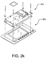
- FIGS. 2 a - 2 n show an example of an implementation of an embodiment of the present invention.
- FIGS. 3 a - 3 c show an example of an implementation of an embodiment of the present invention.
- FIG. 4 shows another example of an implementation of an embodiment of the present invention.
- FIG. 5 shows another example of an implementation of an embodiment of the present invention.
- FIGS. 6 a - 6 e show exemplary implementations of control operations according to an embodiment of the present invention.
- FIG. 7 shows an exemplary implementation of a set up operation according to an embodiment of the present invention.
- FIGS. 8 a and 8 b show an exemplary implementation of a manual test operation according to an embodiment of the present invention.
- FIG. 9 shows another exemplary implementation of a manual test operation according to an embodiment of the present invention.
- FIGS. 2 a - 2 c and FIGS. 3 a - 3 c A controller and an assembly for a system according to an exemplary embodiment of the present invention, is illustrated in FIGS. 2 a - 2 c and FIGS. 3 a - 3 c.
- an exemplary implementation of a controller 300 comprises an LCD display 310 , for example 6.5′′ ⁇ 9′′ in size and having approx 600 ⁇ 480 resolution, small IBM compatible single board PC 320 with hard drive and wireless interface along with press buttons 330 and a rotary encoder 340 for user input.
- wireless control is achieved by using the Ethernet output of the single board PC into an IEEE 802.11 wireless access point.
- IEEE 802.11 was chosen for it's resilience to interference and it's built in networking capabilities.
- the controller is designed to be completely portable having 3 options of power supply:
- the software included with the controller allows the user to monitor both current and voltage output from the system, and to input required test voltage, current and test time if required. Results are stored to the hard drive and available via the USB interface.
- a system 395 (ee FIG. 3 c ), according to an exemplary implementation, houses a PLC controller, IEEE 802.11 wireless access point, motorized auto transformer, current and voltage measurement systems, safety interlock and analog voltage meter. It is powered from a local AC power supply.
- the control system communicates with the controller via an IEEE 802.11 wireless access point and Ethernet connection to the PLC.
- FIG. 2 c illustrates an exemplary implementation 240 of Ethernet to wireless bridge using 802.11 access point 246 and power supply 242 .
- Ethernet adapter for PLC 244 allows communication to/from the PLC via a 10T Ethernet link.
- the Ethernet to wireless bridge allows other users who have permission to access the device.
- the PLC controls the High voltage output and -regulates both voltage and current based on information received from the controller. In the event that this wireless link is lost, the PLC will safely remove output to the HV power supply. External safety interlock is provided by plug P 2 . When there is no connection between the power pins on this connector, High voltage is turned off.
- the power supply control system output is connected to the high voltage multiplier section, which generates a high voltage output proportional to the power supply control system output.
- the current and measurement system allows the PLC controller to read auto transformer voltage and current along with high voltage output voltage and current.
- An analog meter is provided to indicate high voltage output, and is visible to the operator. This indicates that high voltage is present at the output for safety and is independent of the PLC control system.
- FIGS. 2 d and 2 e exemplary implementations for input current 260 and input voltage 280 measuring are illustrated in FIGS. 2 d and 2 e , respectively.
- part 220 of PLC includes a 2 channel analog input for: high voltage output voltage (connection to part 260 via wire number 38 ) and current (connection to part 280 via wire number 39 ), variable DC output for motor speed control (connection to part 220 via wire number 40 ).
- FIGS. 2 a - 2 e input and function switches arc shown with power “OFF”; interlock and overhead contacts are shown closed for ease in trouble shooting; “A” and “B” lines supply control power and carry, for example 114 VAC; the resistors are, for example 1 ⁇ 2W ⁇ 10%; capacitor values are in “UF”; ⁇ symbol denotes wire numbers; and symbol denotes interconnections (top) between pages (bottom).
- controller 300 components of controller 300 are shown in various stages of assembly thereof including top cover 380 .
- Back view of the interior of assembled controller 300 is shown in FIG. 2 n with chassis 390 .
- a wireless method of controlling a high voltage power supply utilizing IEEE 802.11 networking can be extended to include the range of products that Hipotronics currently manufacture. Each of these can then be controlled wirelessly. This allows the operator to be completely electrically isolated from the test system to increase safety.
- controller to wirelessly connect to different products, so that a user who needs to perform multiple tests on a part can use the same controller. All of the test results can then be integrated into one test report and sent out to the factory network if needed. Supervisors, mangers or other allowed persons can also then access the system to view progress or view results.
- a system according to an embodiment of the present invention may offer a galvanically isolated operating platform for performing hipot tests up to 875 kV DC.
- controls and indicators are as follows:
- the information being displayed according to an exemplary implementation is as follows:
- control operations are as follows:
- the control unit should be positioned within 50 feet of a Wireless regulator.
- the AC power to the regulator should be turned to the on position. Hold the ‘Power’ button down on the control unit until the ‘Power Indicator’ is illuminated.
- the screen on the controller will light up and the internal computer will run through its' ‘boot up’ procedure. Do not turn the power off while the computer is booting. When the computer has finished booting the controller will try to connect to a regulator. (See FIG. 6 a .)
- the software is initializing the internal drivers required to communicate with the network.
- a screen as shown in FIG. 6 a will be present for about 1-2 seconds before it changes to a screen as shown in FIG. 6 b.
- the controller is now searching the network to try and locate a compatible regulator device to communicate with. If there is no suitable regulator within range, or the regulator is not yet turned on, then the message as shown in FIG. 6 c will be reported.
- the controller will continue to display this message until the power is turned off, or a suitable regulator is brought into range and powered up. When a regulator has been found the message as shown in FIG. 6 d appears.
- FIGS. 8 a and 8 b When running a manual test, according to an exemplary implementation, information as shown in FIGS. 8 a and 8 b is displayed. The following procedure may be followed:
Landscapes
- Physics & Mathematics (AREA)
- General Physics & Mathematics (AREA)
- Engineering & Computer Science (AREA)
- Computer Networks & Wireless Communication (AREA)
- Testing Electric Properties And Detecting Electric Faults (AREA)
- Testing Relating To Insulation (AREA)
- Arrangements For Transmission Of Measured Signals (AREA)
- Selective Calling Equipment (AREA)
- Remote Monitoring And Control Of Power-Distribution Networks (AREA)
Priority Applications (3)
| Application Number | Priority Date | Filing Date | Title |
|---|---|---|---|
| US11/216,463 US7565253B2 (en) | 2005-09-01 | 2005-09-01 | High-voltage power supply control system and wireless controller and method therefor |
| EP06254429.1A EP1806591B1 (de) | 2005-09-01 | 2006-08-24 | Steuersystem für Hochspannungsleistungszufuhr und drahtlose Steuerung und Verfahren dafür |
| CN2006101118805A CN1975797B (zh) | 2005-09-01 | 2006-08-31 | 高压电源控制系统和无线控制器及其方法 |
Applications Claiming Priority (1)
| Application Number | Priority Date | Filing Date | Title |
|---|---|---|---|
| US11/216,463 US7565253B2 (en) | 2005-09-01 | 2005-09-01 | High-voltage power supply control system and wireless controller and method therefor |
Publications (2)
| Publication Number | Publication Date |
|---|---|
| US20070050159A1 US20070050159A1 (en) | 2007-03-01 |
| US7565253B2 true US7565253B2 (en) | 2009-07-21 |
Family
ID=37499619
Family Applications (1)
| Application Number | Title | Priority Date | Filing Date |
|---|---|---|---|
| US11/216,463 Active 2027-01-17 US7565253B2 (en) | 2005-09-01 | 2005-09-01 | High-voltage power supply control system and wireless controller and method therefor |
Country Status (3)
| Country | Link |
|---|---|
| US (1) | US7565253B2 (de) |
| EP (1) | EP1806591B1 (de) |
| CN (1) | CN1975797B (de) |
Cited By (10)
| Publication number | Priority date | Publication date | Assignee | Title |
|---|---|---|---|---|
| US20090201171A1 (en) * | 2008-02-07 | 2009-08-13 | Demartini Paul | Small in-home utility services display device |
| US20090309754A1 (en) * | 2008-06-16 | 2009-12-17 | Jimmy Bou | Wireless current transformer |
| US20120086632A1 (en) * | 2010-10-11 | 2012-04-12 | Powertech Industrial Co., Ltd. | Electric power information user interface, display method and apparatus thereof |
| RU2511038C2 (ru) * | 2012-08-02 | 2014-04-10 | Федеральное государственное бюджетное учреждение науки Институт автоматики и процессов управления Дальневосточного отделения Российской академии наук (ИАПУ ДВО РАН) | Способ контроля технического состояния высоковольтного трансформаторного оборудования |
| WO2014071293A1 (en) * | 2012-11-05 | 2014-05-08 | Doble Engineering Company | Method and apparatus for testing utility power devices |
| US9002265B2 (en) | 2012-07-26 | 2015-04-07 | General Electric Company | Method, system and apparatus for galvanic isolation of gate-controlled devices |
| US9341665B2 (en) | 2012-04-18 | 2016-05-17 | Lear Corporation | Method and apparatus for high voltage isolation monitor for a vehicle |
| US20160299175A1 (en) * | 2015-04-09 | 2016-10-13 | Fisher-Rosemount Systems, Inc. | Method for Supplying Fieldbus Communication and Power from a Handheld Maintenance Tool in a Hazardous Area Using a Single Lead Set |
| US9874613B2 (en) | 2012-11-05 | 2018-01-23 | Doble Engineering Company | Method and system of apparatuses for testing utility power devices |
| CN109188068A (zh) * | 2018-08-06 | 2019-01-11 | 国网山东省电力公司淄博供电公司 | 三段式u型可调可带电安装高压计量装置 |
Families Citing this family (9)
| Publication number | Priority date | Publication date | Assignee | Title |
|---|---|---|---|---|
| US20070094524A1 (en) * | 2005-10-25 | 2007-04-26 | Microchip Technology Incorporated | Using digital communications in the control of load sharing between paralleled power supplies |
| GB2456823B (en) * | 2008-01-25 | 2013-07-24 | Control Tech Ltd | A DC motor drive |
| CN102625916A (zh) * | 2009-07-18 | 2012-08-01 | 纳克斯伦特有限责任公司 | 电力系统传感器装置、电力系统监测方法以及电力系统监测系统 |
| CN102063877B (zh) * | 2009-11-12 | 2013-01-02 | 群康科技(深圳)有限公司 | 液晶显示器及其检测方法 |
| CN102478638A (zh) * | 2010-11-27 | 2012-05-30 | 西安博昱新能源有限公司 | Led路灯电源综合测试系统 |
| US10310006B2 (en) | 2013-03-15 | 2019-06-04 | Hubbell Incorporated | DC high potential insulation breakdown test system and method |
| CN104635066A (zh) * | 2015-03-10 | 2015-05-20 | 李景禄 | 智能型绝缘参数试验的残余电荷检测及放电保护方法 |
| CN105355017A (zh) * | 2015-11-04 | 2016-02-24 | 王亲武 | 基于Zigbee技术的智能无线测温终端 |
| CN105486894A (zh) * | 2015-11-27 | 2016-04-13 | 国网河南宜阳县供电公司 | 一种无人高压计量配电装置及方法 |
Citations (23)
| Publication number | Priority date | Publication date | Assignee | Title |
|---|---|---|---|---|
| US3609523A (en) | 1969-04-02 | 1971-09-28 | Wayne Electronic Products Co | Automatic test apparatus for phase comparison protective relay systems and the like |
| US3991367A (en) | 1976-01-20 | 1976-11-09 | The United States Of America As Represented By The Secretary Of The Interior | Detection of potential on high-voltage transmission lines |
| US4384289A (en) | 1981-01-23 | 1983-05-17 | General Electric Company | Transponder unit for measuring temperature and current on live transmission lines |
| US4684887A (en) | 1986-06-24 | 1987-08-04 | General Battery Corporation | High voltage test confirmation apparatus |
| US4714893A (en) | 1983-04-13 | 1987-12-22 | Niagara Mohawk Power Corporation | Apparatus for measuring the potential of a transmission line conductor |
| US4794327A (en) | 1983-04-13 | 1988-12-27 | Fernandes Roosevelt A | Electrical parameter sensing module for mounting on and removal from an energized high voltage power conductor |
| US5136285A (en) | 1988-05-20 | 1992-08-04 | Man Design Co., Ltd. | Portable data transmitting/receiving apparatus |
| US5426360A (en) | 1994-02-17 | 1995-06-20 | Niagara Mohawk Power Corporation | Secondary electrical power line parameter monitoring apparatus and system |
| US5640155A (en) | 1992-02-18 | 1997-06-17 | O'connor Springer | Meter cradle with wireless communication port |
| US5815956A (en) | 1996-04-30 | 1998-10-06 | Curtis International , Inc. | Vehicle mounting assembly for a snow plow with hidden actuator drive |
| US6014083A (en) | 1996-01-31 | 2000-01-11 | Siemens Aktiengesellschaft | Metalclad switchgear assembly with partial discharge detection |
| US6177884B1 (en) | 1998-11-12 | 2001-01-23 | Hunt Technologies, Inc. | Integrated power line metering and communication method and apparatus |
| US6239723B1 (en) | 1996-01-31 | 2001-05-29 | Siemens Aktiengesellschaft | Encapsulated installation |
| US20010040446A1 (en) | 2000-04-13 | 2001-11-15 | Sterling Lapinksi | Apparatus and method for the measurement and monitoring of electrical power generation and transmission |
| US20030117146A1 (en) | 2000-06-26 | 2003-06-26 | Snap-On Technologies, Inc. | Alternator testing method and system using timed application of load |
| US6617840B2 (en) | 2001-03-22 | 2003-09-09 | Walter S Bierer | Wireless alternating current phasing voltmeter |
| US6711512B2 (en) | 2001-08-07 | 2004-03-23 | Korea Electric Power Data Network Co. Ltd. | Pole transformer load monitoring system using wireless internet network |
| US6778921B2 (en) | 2001-04-06 | 2004-08-17 | Eni Technology, Inc. | Modular architecture for industrial power delivery system |
| US20040178918A1 (en) | 2002-06-19 | 2004-09-16 | Lockhart Bradley W. | Battery monitor |
| US20040183522A1 (en) | 2003-03-19 | 2004-09-23 | Power Measurement Ltd. | Power line sensors and systems incorporating same |
| US20050030693A1 (en) | 2004-06-23 | 2005-02-10 | Bela Deak | Protective relay test device |
| US7058524B2 (en) * | 2002-10-25 | 2006-06-06 | Hudson Bay Wireless, Llc | Electrical power metering system |
| US7076378B1 (en) * | 2002-11-13 | 2006-07-11 | Current Technologies, Llc | Device and method for providing power line characteristics and diagnostics |
Family Cites Families (7)
| Publication number | Priority date | Publication date | Assignee | Title |
|---|---|---|---|---|
| CN87209275U (zh) * | 1987-06-16 | 1988-07-20 | 王礼卿 | 微安表的无线电遥控及保护装置 |
| US5136258A (en) | 1989-04-28 | 1992-08-04 | Sgs-Thomson Microelectronics S.R.L. | Circuit arrangement for enhancing the transconductance of a differential amplifier stage comprising MOS transistors |
| CN1174365A (zh) * | 1997-05-22 | 1998-02-25 | 张锦雷 | 电力系统电流参数无导线传输监测方法 |
| CN2396458Y (zh) * | 1999-07-27 | 2000-09-13 | 常州供电局 | 用于进行高压试验的电源装置 |
| US6677761B1 (en) * | 2001-12-12 | 2004-01-13 | The United States Of America As Represented By The Administrator Of The National Aeronautics And Space Administration | Wire insulation defect detector |
| EP1491903A1 (de) * | 2003-05-12 | 2004-12-29 | Kasmatic Innovation A/S | Faseroptisches Faraday-Effekt-Sensor |
| US7282944B2 (en) * | 2003-07-25 | 2007-10-16 | Power Measurement, Ltd. | Body capacitance electric field powered device for high voltage lines |
-
2005
- 2005-09-01 US US11/216,463 patent/US7565253B2/en active Active
-
2006
- 2006-08-24 EP EP06254429.1A patent/EP1806591B1/de active Active
- 2006-08-31 CN CN2006101118805A patent/CN1975797B/zh active Active
Patent Citations (23)
| Publication number | Priority date | Publication date | Assignee | Title |
|---|---|---|---|---|
| US3609523A (en) | 1969-04-02 | 1971-09-28 | Wayne Electronic Products Co | Automatic test apparatus for phase comparison protective relay systems and the like |
| US3991367A (en) | 1976-01-20 | 1976-11-09 | The United States Of America As Represented By The Secretary Of The Interior | Detection of potential on high-voltage transmission lines |
| US4384289A (en) | 1981-01-23 | 1983-05-17 | General Electric Company | Transponder unit for measuring temperature and current on live transmission lines |
| US4714893A (en) | 1983-04-13 | 1987-12-22 | Niagara Mohawk Power Corporation | Apparatus for measuring the potential of a transmission line conductor |
| US4794327A (en) | 1983-04-13 | 1988-12-27 | Fernandes Roosevelt A | Electrical parameter sensing module for mounting on and removal from an energized high voltage power conductor |
| US4684887A (en) | 1986-06-24 | 1987-08-04 | General Battery Corporation | High voltage test confirmation apparatus |
| US5136285A (en) | 1988-05-20 | 1992-08-04 | Man Design Co., Ltd. | Portable data transmitting/receiving apparatus |
| US5640155A (en) | 1992-02-18 | 1997-06-17 | O'connor Springer | Meter cradle with wireless communication port |
| US5426360A (en) | 1994-02-17 | 1995-06-20 | Niagara Mohawk Power Corporation | Secondary electrical power line parameter monitoring apparatus and system |
| US6014083A (en) | 1996-01-31 | 2000-01-11 | Siemens Aktiengesellschaft | Metalclad switchgear assembly with partial discharge detection |
| US6239723B1 (en) | 1996-01-31 | 2001-05-29 | Siemens Aktiengesellschaft | Encapsulated installation |
| US5815956A (en) | 1996-04-30 | 1998-10-06 | Curtis International , Inc. | Vehicle mounting assembly for a snow plow with hidden actuator drive |
| US6177884B1 (en) | 1998-11-12 | 2001-01-23 | Hunt Technologies, Inc. | Integrated power line metering and communication method and apparatus |
| US20010040446A1 (en) | 2000-04-13 | 2001-11-15 | Sterling Lapinksi | Apparatus and method for the measurement and monitoring of electrical power generation and transmission |
| US20030117146A1 (en) | 2000-06-26 | 2003-06-26 | Snap-On Technologies, Inc. | Alternator testing method and system using timed application of load |
| US6617840B2 (en) | 2001-03-22 | 2003-09-09 | Walter S Bierer | Wireless alternating current phasing voltmeter |
| US6778921B2 (en) | 2001-04-06 | 2004-08-17 | Eni Technology, Inc. | Modular architecture for industrial power delivery system |
| US6711512B2 (en) | 2001-08-07 | 2004-03-23 | Korea Electric Power Data Network Co. Ltd. | Pole transformer load monitoring system using wireless internet network |
| US20040178918A1 (en) | 2002-06-19 | 2004-09-16 | Lockhart Bradley W. | Battery monitor |
| US7058524B2 (en) * | 2002-10-25 | 2006-06-06 | Hudson Bay Wireless, Llc | Electrical power metering system |
| US7076378B1 (en) * | 2002-11-13 | 2006-07-11 | Current Technologies, Llc | Device and method for providing power line characteristics and diagnostics |
| US20040183522A1 (en) | 2003-03-19 | 2004-09-23 | Power Measurement Ltd. | Power line sensors and systems incorporating same |
| US20050030693A1 (en) | 2004-06-23 | 2005-02-10 | Bela Deak | Protective relay test device |
Cited By (15)
| Publication number | Priority date | Publication date | Assignee | Title |
|---|---|---|---|---|
| US20090201171A1 (en) * | 2008-02-07 | 2009-08-13 | Demartini Paul | Small in-home utility services display device |
| US20090309754A1 (en) * | 2008-06-16 | 2009-12-17 | Jimmy Bou | Wireless current transformer |
| US20120086632A1 (en) * | 2010-10-11 | 2012-04-12 | Powertech Industrial Co., Ltd. | Electric power information user interface, display method and apparatus thereof |
| US9341665B2 (en) | 2012-04-18 | 2016-05-17 | Lear Corporation | Method and apparatus for high voltage isolation monitor for a vehicle |
| US9002265B2 (en) | 2012-07-26 | 2015-04-07 | General Electric Company | Method, system and apparatus for galvanic isolation of gate-controlled devices |
| RU2511038C2 (ru) * | 2012-08-02 | 2014-04-10 | Федеральное государственное бюджетное учреждение науки Институт автоматики и процессов управления Дальневосточного отделения Российской академии наук (ИАПУ ДВО РАН) | Способ контроля технического состояния высоковольтного трансформаторного оборудования |
| WO2014071293A1 (en) * | 2012-11-05 | 2014-05-08 | Doble Engineering Company | Method and apparatus for testing utility power devices |
| US9482712B2 (en) | 2012-11-05 | 2016-11-01 | Doble Engineering Company | Method and apparatus for testing utility power devices |
| US9632128B2 (en) | 2012-11-05 | 2017-04-25 | Doble Engineering Company | Method and apparatus for testing utility power devices |
| US9874613B2 (en) | 2012-11-05 | 2018-01-23 | Doble Engineering Company | Method and system of apparatuses for testing utility power devices |
| US20160299175A1 (en) * | 2015-04-09 | 2016-10-13 | Fisher-Rosemount Systems, Inc. | Method for Supplying Fieldbus Communication and Power from a Handheld Maintenance Tool in a Hazardous Area Using a Single Lead Set |
| US9709602B2 (en) * | 2015-04-09 | 2017-07-18 | Fisher-Rosemount Systems, Inc. | Method for supplying fieldbus communication and power from a handheld maintenance tool in a hazardous area using a single lead set |
| US20170331240A1 (en) * | 2015-04-09 | 2017-11-16 | Fisher-Rosemount Systems, Inc. | Two-Prong Plug of a Single Lead Set for Supplying Fieldbus Communication and Power from a Handheld Maintenance Tool in a Hazardous Area |
| US10270215B2 (en) * | 2015-04-09 | 2019-04-23 | Fisher-Rosemount Systems, Inc. | Two-prong plug of a single lead set for supplying fieldbus communication and power from a handheld maintenance tool in a hazardous area |
| CN109188068A (zh) * | 2018-08-06 | 2019-01-11 | 国网山东省电力公司淄博供电公司 | 三段式u型可调可带电安装高压计量装置 |
Also Published As
| Publication number | Publication date |
|---|---|
| EP1806591A2 (de) | 2007-07-11 |
| CN1975797B (zh) | 2011-06-15 |
| EP1806591A3 (de) | 2012-06-06 |
| US20070050159A1 (en) | 2007-03-01 |
| EP1806591B1 (de) | 2017-09-20 |
| CN1975797A (zh) | 2007-06-06 |
Similar Documents
| Publication | Publication Date | Title |
|---|---|---|
| US7565253B2 (en) | High-voltage power supply control system and wireless controller and method therefor | |
| US5744962A (en) | Automated data storing battery tester and multimeter | |
| US7209804B2 (en) | System and method for providing remote monitoring of voltage power transmission and distribution devices | |
| US20110106280A1 (en) | Automated battery scanning, repair, and optimization | |
| US20090248329A1 (en) | Arc fault root-cause finder system and method | |
| US20030132753A1 (en) | Circuit breaker with integral testing unit | |
| US20050038614A1 (en) | Remote battery monitoring systems and sensors | |
| US20120116745A1 (en) | Electric Vehicle Simulator and Analyzer (EVSA) for Electric Vehicle Supply Equipment | |
| US20110267067A1 (en) | Electronic battery tester | |
| KR101136537B1 (ko) | 근거리 무선 통신을 이용한 전력 측정 시스템 | |
| CA2990970C (en) | Voltage measurement and wireless communication system | |
| CN1987487B (zh) | 由主机控制的附属装置电压管理系统 | |
| EP1005708B1 (de) | Leiterplattenanordnung | |
| CN113109755B (zh) | 一种用于计量现场作业终端的检测装置 | |
| HK1106292A (en) | High-voltage power supply control system and wireless controller and method therefor | |
| HK1106292B (en) | High-voltage power supply control system and wireless controller and method therefor | |
| WO2008003917A1 (en) | Apparatus for testing wiring | |
| CN216771840U (zh) | 一种多通道二次电缆绝缘检测系统 | |
| KR100783136B1 (ko) | 다중릴레이검사장치 | |
| CN211263622U (zh) | 绝缘电阻检测装置和系统 | |
| KR20060063829A (ko) | 활선 상태 변성기용 전류 비오차 시험방법 및 그 장치 | |
| KR102897938B1 (ko) | 다채널의 디씨 미터 및 그의 제어방법 | |
| CN223910997U (zh) | 一种便携式掘进机电气元件检测装置 | |
| CN223743007U (zh) | 自动调节交流输出电压的调压器 | |
| CN221946147U (zh) | 电池的电量持续时间的测量系统 |
Legal Events
| Date | Code | Title | Description |
|---|---|---|---|
| AS | Assignment |
Owner name: HUBBELL INCORPORATED, CONNECTICUT Free format text: ASSIGNMENT OF ASSIGNORS INTEREST;ASSIGNORS:EWERS, CHRISTOPHER F.;SOWERBY, MICHAEL J.;REEL/FRAME:017261/0091;SIGNING DATES FROM 20051103 TO 20051110 |
|
| FEPP | Fee payment procedure |
Free format text: PAYOR NUMBER ASSIGNED (ORIGINAL EVENT CODE: ASPN); ENTITY STATUS OF PATENT OWNER: LARGE ENTITY |
|
| STCF | Information on status: patent grant |
Free format text: PATENTED CASE |
|
| FPAY | Fee payment |
Year of fee payment: 4 |
|
| FPAY | Fee payment |
Year of fee payment: 8 |
|
| FEPP | Fee payment procedure |
Free format text: 11.5 YR SURCHARGE- LATE PMT W/IN 6 MO, LARGE ENTITY (ORIGINAL EVENT CODE: M1556); ENTITY STATUS OF PATENT OWNER: LARGE ENTITY |
|
| MAFP | Maintenance fee payment |
Free format text: PAYMENT OF MAINTENANCE FEE, 12TH YEAR, LARGE ENTITY (ORIGINAL EVENT CODE: M1553); ENTITY STATUS OF PATENT OWNER: LARGE ENTITY Year of fee payment: 12 |
|
| FEPP | Fee payment procedure |
Free format text: MAINTENANCE FEE REMINDER MAILED (ORIGINAL EVENT CODE: REM.); ENTITY STATUS OF PATENT OWNER: LARGE ENTITY |