US7556129B2 - Motor brake - Google Patents
Motor brake Download PDFInfo
- Publication number
- US7556129B2 US7556129B2 US11/306,001 US30600105A US7556129B2 US 7556129 B2 US7556129 B2 US 7556129B2 US 30600105 A US30600105 A US 30600105A US 7556129 B2 US7556129 B2 US 7556129B2
- Authority
- US
- United States
- Prior art keywords
- brake
- bearing
- motor
- release
- stop members
- Prior art date
- Legal status (The legal status is an assumption and is not a legal conclusion. Google has not performed a legal analysis and makes no representation as to the accuracy of the status listed.)
- Active, expires
Links
- 239000000463 material Substances 0.000 description 8
- 238000003466 welding Methods 0.000 description 5
- 230000005540 biological transmission Effects 0.000 description 3
- 230000000881 depressing effect Effects 0.000 description 2
- 238000012986 modification Methods 0.000 description 2
- 230000004048 modification Effects 0.000 description 2
- 239000002184 metal Substances 0.000 description 1
- 230000037361 pathway Effects 0.000 description 1
- 238000007789 sealing Methods 0.000 description 1
- 238000013022 venting Methods 0.000 description 1
Images


Classifications
-
- B—PERFORMING OPERATIONS; TRANSPORTING
- B65—CONVEYING; PACKING; STORING; HANDLING THIN OR FILAMENTARY MATERIAL
- B65B—MACHINES, APPARATUS OR DEVICES FOR, OR METHODS OF, PACKAGING ARTICLES OR MATERIALS; UNPACKING
- B65B13/00—Bundling articles
- B65B13/18—Details of, or auxiliary devices used in, bundling machines or bundling tools
- B65B13/185—Details of tools
- B65B13/187—Motor means
-
- B—PERFORMING OPERATIONS; TRANSPORTING
- B65—CONVEYING; PACKING; STORING; HANDLING THIN OR FILAMENTARY MATERIAL
- B65B—MACHINES, APPARATUS OR DEVICES FOR, OR METHODS OF, PACKAGING ARTICLES OR MATERIALS; UNPACKING
- B65B13/00—Bundling articles
- B65B13/18—Details of, or auxiliary devices used in, bundling machines or bundling tools
Definitions
- the present invention pertains to an improved brake and release for a strapping tool. More particularly, the present invention is directed to a one-way clutch brake and release for a powered strapping tool.
- Strapping tools are well-known in the art. These tools come in a wide variety of types, from fully manual tools to automatic, table-top tools. These tools are generally specifically designed for use with metal strapping or plastic/polymeric type strapping.
- a strapper for applying plastic or polymeric strapping materials is powered to provide energy for tensioning the strap and adhering the strapping material onto itself.
- a typical strapper tool includes a body, one or more motors, a foot (which rests on the load), a tensioning wheel, a vibrating or sealing element and, typically, a pneumatic module to route air and provide control of the tool.
- first and second courses of strap material are passed over the foot of the tool, between the foot and the tensioning wheel.
- the strap is tensioned by rotation of the wheel.
- As the strap is tensioned, is also tightens onto the tool foot, holding the foot to the load.
- the strap is sealed to itself (as by welding) and the free end of the strap is cut. Although this does in fact strap the load, it also retains the tool (at the foot) sealed to the load.
- the many tools are configured to allow the tensioning wheel to rollback, a small amount. This retains the strap in tension, but releases tension just enough to allow the tool foot to be pulled from between the strap and the load.
- pneumatic systems are known that use a delay in the pneumatic circuit that permits a slight rollback following tensioning.
- Other strapping tools use a complex gearing arrangement to permit rollback.
- a brake assembly is configured for use with a tensioning motor for a strapping tool.
- the motor has a housing and an output shaft operably connected to a tensioning wheel.
- the tensioning wheel rotates in a first direction to tension the strap and in a second reverse direction to relieve tension in the strap.
- Tension release is required to be able to remove the tool from the load being strapped.
- the loosening or rollback must be controlled to prevent excessive slack in the strap.
- the brake assembly includes a one-way bearing operably connected to the motor output shaft.
- the bearing permits the shaft to rotate relative to the bearing in the first direction and prevents rotation of the shaft relative to the bearing in the reverse direction.
- the bearing has at least two (and preferably two) stop members thereon.
- a brake element is operably mounted to the motor housing and is movable toward and away from the bearing for movement into and out of engagement with one of the bearing stop members.
- the brake element stops reverse rotation of the motor shaft and bearing when the brake element is engaged with one of the bearing stop members.
- a brake release is operably connected to the brake element for moving the brake element into and out of engagement with the bearing stop member.
- a biasing element biases the brake element into engagement with the bearing stop member.
- the motor When the brake is engaged with the bearing stop member, the motor can freely rotate in the first direction (to tension the strap) but cannot rotate in the second reverse direction.
- the motor and bearing
- the motor can freely rotate in the reverse direction to slightly loosen the strap, until the brake release is reengaged with one of the bearing stop members.
- the bearing in a present brake assembly, includes a circumferential trough formed therein and includes outwardly extending projections that form the stop members.
- a preferred bearing includes two stop members.
- the brake release is pivotally mounted to the motor housing by a pivot.
- a finger release is spaced from the pivot and the brake element is operably connected to the brake release between the finger release and the pivot.
- a cam operably connects the brake release and the brake element.
- the cam is configured to translate movement of the brake release into an opposite movement of the brake element.
- the cam includes a central disk portion and a pair of pins extending outwardly from opposing side surfaces of the disk.
- the pins are disposed about 180 degrees from one another.
- the brake release and the brake element each include a slot to receive their respective pins.
- the brake release is biased to maintain the brake element in the engaged position.
- the biasing element is disposed between the pivot and the finger release, and more particularly, between the finger release and the cam.
- a strapper motor is also disclosed.
- FIG. 1 is a perspective view of an exemplary strapping tool having a motor brake embodying the principles of the present invention
- FIG. 2 is a side view of the strapper
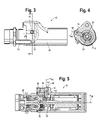
- FIG. 3 is a side view of the strapper tensioning motor
- FIG. 4 is a cross-sectional view taken along line 4 - 4 of FIG. 3 ;
- FIG. 5 is a longitudinal cross-sectional view of the motor
- FIG. 6 is a sectional view illustrating the brake release
- FIG. 7 is a perspective view of the motor showing the release
- FIG. 8 is an exploded view of the brake release, cam and plunger
- FIG. 9 is a front view of the bearing
- FIG. 10 is a wire frame perspective illustration of the bearing
- FIG. 11 is a top view of the bearing.
- FIGS. 12A and 12B are front and side views of the cam.
- FIG. 1 there is shown an exemplary pneumatic motor strapper or strapping tool 10 that has a motor brake 12 embodying the principles of the present invention.
- the tool 10 is configured to tension a strap S around a load L, weld the strap S material onto itself and sever a feed end F of the strap S.
- the strap S material will be referred to as having a feed end F which is the supply end of the material and a free end D which is that end of the material that is fed around the load L and reinserted into the strapping tool 10 .
- the tool 10 includes, generally, a body 14 , a foot 16 , a tensioning motor 18 , a weld motor 20 , a housing 22 and a pneumatic module 24 .
- the pneumatic module 24 is mounted to the housing 22 which is mounted to the body 14 and provides pneumatic pathways between the module 24 , the housing 22 and the tensioning and welding motors 18 , 20 , for introducing and venting a compressed gas, such as compressed air, to and from the motors 18 , 20 .
- a compressed gas such as compressed air
- the tensioning motor 18 is pneumatic actuated and drives a tensioning wheel 26 . It will be appreciated that the power output of the pneumatic motor 18 is low, whereas the force required to tension the strap S is relatively high. Accordingly, the drive or transmission 28 (operably connecting the motor 18 to the wheel 26 ) is at a relatively high gear ratio, on the order of about 20:1 to 30:1. Thus, the output shaft 30 of the motor 18 rotates a relatively high speed, but at low power, and the transmission 28 translates the high speed/low power output at the shaft 30 to high power/low speed at the tension wheel 26 .
- first and second courses F, D of strap S material are passed over the foot 16 of the tool 10 , between the foot 16 and the tensioning wheel 26 .
- the strap S is tensioned by actuation of the tensioning motor 18 which rotates the tensioning wheel 26 .
- the strap S is sealed to itself (as by welding) and the free end F of the strap S is cut. Although this does in fact strap the load L, it also retains the tool 10 (at the foot 16 ) tightly held to the load L.
- the present brake assembly 12 includes a one-way bearing 34 that is mounted to the motor output shaft 30 and a cooperating brake assembly 36 .
- the bearing 34 and brake assembly 36 permits the motor shaft 30 to freely rotate relative to the bearing in one direction (forwardly), the tensioning direction, but prevents (rearward) rotation in an opposite direction.
- the bearing 34 includes at least one and preferably a pair of generally radially outwardly oriented stops 38 .
- the stops 38 extend outwardly from a circumferential lip 40 on the bearing 34 at the bore 42 through which the shaft 30 extends.
- the bearing 34 is formed as a collar with a circumferential channel 44 formed therein.
- the stops 38 are formed as wall portions that extend into the channel 44 .
- the stops 38 are generally radially formed, oriented slightly tangential, as will be described below (see FIG. 9 ).
- the assembly 36 includes a plunger 46 that is fitted into an opening 48 in the motor housing 50 .
- the plunger 46 is configured to move in and out (toward and away from the bearing 34 ) along a line A 46 that projects through the central axis A 18 of the motor 18 and shaft 30 .
- a finger 52 at the end of the plunger 46 moves into the channel 44 to engage one of the stops 38 and to disengage from the stop 38 .
- the plunger 46 is biased in the engaged position by a spring 54 . When the plunger 46 is in the engaged position it contacts the stop 38 to prevent the motor 18 from rotating in the reverse direction.
- the plunger 46 includes a slot 56 formed therein.
- a manual brake release lever 58 is mounted to the motor housing 50 .
- the brake lever 58 includes a body 60 that is received in the housing 50 .
- the body 60 is mounted to the housing 50 at a pivot 62 .
- a finger release 64 is mounted to the body 50 spaced from the pivot 62 to actuate or move the lever 58 .
- An elongated slot 66 is formed in the body 60 between the finger release 64 and the pivot 62 .
- a cam 68 is mounted between the finger release 64 and the plunger 46 .
- the cam 68 has a round, disk-like body 70 with pins 72 , 74 extending from the disk 70 , on opposite sides thereof.
- the pins 72 , 74 are mounted about 180 degrees from one another.
- the lever slot/cam/plunger slot ( 66 / 68 / 56 ) arrangement serves to translate the downward movement of the release lever finger pad 64 to an upward movement of the plunger 46 . That is, because the pins 72 , 74 are located 180 degrees from one another, as the release lever pin 72 is urged inward by depressing the pad 64 , it rotates the central disk 70 , which in turn rotates the plunger pin 74 upward (or outwardly) to move the plunger finger 52 out of engagement with the bearing stop 38 .
- the elongated slots 66 , 56 in the lever body 60 and plunger 46 permit movement without binding between the pins 72 , 74 and their respective openings, 66 , 56 . This permits the bearing 34 and motor 18 to rotate in the rearward direction.
- the finger 52 contacts the stop 38 to prevent rearward rotation of the bearing 34 and motor 18 .
- the location and orientation of the stops 38 are such that the finger 52 rests against the surface of the stop 38 , rather than contact merely at a point on the stop 38 .
- the wall (as indicated at 39 ) that defines the stop 38 is rounded (along with the finger 52 ), again, to maintain a relatively large contact area to facilitate ready disengagement of the finger 52 from the stop 38 .
- the motor 18 rotates clockwise (as seen in FIG. 4 ), the plunger 46 is in the engaged position, but the motor shaft 30 rotates freely relative to the one-way bearing 34 .
- the bearing 34 may nevertheless rotate clockwise with the shaft 30 until the rear side of the stop 38 contacts the finger 52 .
- release of the brake 36 can result in a 1 ⁇ 2 rotation (e.g., 180 degree rotation) of the motor 18 (until the opposing stop 38 engages the finger 52 ), because of the gear ratio of the motor 18 and tension wheel 26 (about 20:1 to 30:1), that 1 ⁇ 2 rotation of the motor 18 translates into about 1/50 rotation of the tension wheel 26 . Thus, excessive loosening of the strap does not occur.
- a 1 ⁇ 2 rotation e.g. 180 degree rotation
- the tensioning wheel 26 In order to release the tool 10 from the tensioned strap S on the load L, the tensioning wheel 26 must be allowed to rollback subsequent to forming the strap weld. Tension is maintained during welding and rollback is then permitted, following welding, to allow for removal of the tool 10 from the load L.
- the present brake system 12 allows this rollback without excessive slack in the strap S, in an arrangement that eliminates complex gearing and/or pneumatics systems.
Landscapes
- Engineering & Computer Science (AREA)
- Mechanical Engineering (AREA)
- Basic Packing Technique (AREA)
- Braking Arrangements (AREA)
Abstract
Description
Claims (18)
Priority Applications (7)
| Application Number | Priority Date | Filing Date | Title |
|---|---|---|---|
| US11/306,001 US7556129B2 (en) | 2005-12-14 | 2005-12-14 | Motor brake |
| AU2006325297A AU2006325297B2 (en) | 2005-12-14 | 2006-10-30 | Motor brake |
| EP06827142A EP1960268B1 (en) | 2005-12-14 | 2006-10-30 | Motor brake |
| PCT/US2006/042429 WO2007070176A1 (en) | 2005-12-14 | 2006-10-30 | Motor brake |
| BRPI0619987-9A BRPI0619987B1 (en) | 2005-12-14 | 2006-10-30 | CLUTCH BRAKE AND TRIGGER FOR A DRIVE BALING TOOL |
| DE602006013877T DE602006013877D1 (en) | 2005-12-14 | 2006-10-30 | MOTOR BRAKE |
| CA2633831A CA2633831C (en) | 2005-12-14 | 2006-10-30 | Motor brake |
Applications Claiming Priority (1)
| Application Number | Priority Date | Filing Date | Title |
|---|---|---|---|
| US11/306,001 US7556129B2 (en) | 2005-12-14 | 2005-12-14 | Motor brake |
Publications (2)
| Publication Number | Publication Date |
|---|---|
| US20070131496A1 US20070131496A1 (en) | 2007-06-14 |
| US7556129B2 true US7556129B2 (en) | 2009-07-07 |
Family
ID=37715810
Family Applications (1)
| Application Number | Title | Priority Date | Filing Date |
|---|---|---|---|
| US11/306,001 Active 2027-09-19 US7556129B2 (en) | 2005-12-14 | 2005-12-14 | Motor brake |
Country Status (7)
| Country | Link |
|---|---|
| US (1) | US7556129B2 (en) |
| EP (1) | EP1960268B1 (en) |
| AU (1) | AU2006325297B2 (en) |
| BR (1) | BRPI0619987B1 (en) |
| CA (1) | CA2633831C (en) |
| DE (1) | DE602006013877D1 (en) |
| WO (1) | WO2007070176A1 (en) |
Cited By (7)
| Publication number | Priority date | Publication date | Assignee | Title |
|---|---|---|---|---|
| US20160016682A1 (en) * | 2014-07-21 | 2016-01-21 | Signode Industrial Group Llc | Electrically powered combination hand-held strapping tool |
| US10370132B2 (en) | 2012-09-24 | 2019-08-06 | Signode Industrial Group Llc | Strapping device having a pivotable rocker |
| US10464699B2 (en) | 2011-10-04 | 2019-11-05 | Signode Industrial Group Llc | Sealing tool for strap |
| US10577137B2 (en) | 2015-12-09 | 2020-03-03 | Signode Industrial Group Llc | Electrically powered combination hand-held notch-type strapping tool |
| US11136151B1 (en) * | 2018-04-23 | 2021-10-05 | Michael Baker | Orbital wrapping machine |
| US12145755B2 (en) | 2019-02-15 | 2024-11-19 | Samuel, Son & Co. (Usa) Inc. | Hand held strapping tool |
| US12397943B2 (en) | 2022-11-29 | 2025-08-26 | Samuel, Son & Co. (Usa) Inc. | Handheld strapping device |
Families Citing this family (3)
| Publication number | Priority date | Publication date | Assignee | Title |
|---|---|---|---|---|
| US10351275B2 (en) | 2015-05-12 | 2019-07-16 | Signode Industrial Group Llc | Tension head with tension wheel cam biasing element for modular steel strapping machine |
| KR102315941B1 (en) * | 2021-01-18 | 2021-10-22 | 장근철 | Auto strapping packaging tool having clamp fixing apparatus |
| CN219056664U (en) * | 2022-09-23 | 2023-05-23 | 浙江维派包装设备有限公司 | Tensioning mechanism |
Citations (7)
| Publication number | Priority date | Publication date | Assignee | Title |
|---|---|---|---|---|
| GB1562333A (en) | 1976-02-21 | 1980-03-12 | Max Co Ltd | Automatic binder |
| DE10026200A1 (en) | 2000-05-26 | 2001-11-29 | Cyklop Gmbh | Device for tensioning strapping |
| US6338375B1 (en) * | 1998-12-11 | 2002-01-15 | Kohan Kogyo Co., Ltd. | Tool for tightening and melt-adhering a strap |
| EP1357033A2 (en) | 2002-04-23 | 2003-10-29 | TITAN Umreifungstechnik GmbH & Co.KG | Apparatus for strapping goods with a band |
| EP1371560A1 (en) | 2002-06-14 | 2003-12-17 | Illinois Tool Works Inc. | Dual motor strapper |
| WO2005002972A1 (en) | 2003-06-20 | 2005-01-13 | Messersi' Packaging S.R.L. | Strapping machine with strap feedomg amd tightening unit |
| WO2005070766A1 (en) | 2004-01-21 | 2005-08-04 | Ats Automatic Taping Systems Ag | Axial bearing for a spooling roller |
-
2005
- 2005-12-14 US US11/306,001 patent/US7556129B2/en active Active
-
2006
- 2006-10-30 WO PCT/US2006/042429 patent/WO2007070176A1/en not_active Ceased
- 2006-10-30 BR BRPI0619987-9A patent/BRPI0619987B1/en not_active IP Right Cessation
- 2006-10-30 AU AU2006325297A patent/AU2006325297B2/en not_active Ceased
- 2006-10-30 CA CA2633831A patent/CA2633831C/en not_active Expired - Fee Related
- 2006-10-30 DE DE602006013877T patent/DE602006013877D1/en active Active
- 2006-10-30 EP EP06827142A patent/EP1960268B1/en not_active Not-in-force
Patent Citations (11)
| Publication number | Priority date | Publication date | Assignee | Title |
|---|---|---|---|---|
| GB1562333A (en) | 1976-02-21 | 1980-03-12 | Max Co Ltd | Automatic binder |
| US6338375B1 (en) * | 1998-12-11 | 2002-01-15 | Kohan Kogyo Co., Ltd. | Tool for tightening and melt-adhering a strap |
| DE10026200A1 (en) | 2000-05-26 | 2001-11-29 | Cyklop Gmbh | Device for tensioning strapping |
| US20030056337A1 (en) * | 2000-05-26 | 2003-03-27 | Detlef Scholl | Device for tightening strapping bands |
| EP1357033A2 (en) | 2002-04-23 | 2003-10-29 | TITAN Umreifungstechnik GmbH & Co.KG | Apparatus for strapping goods with a band |
| US20030221566A1 (en) * | 2002-04-23 | 2003-12-04 | Titan Umreifungstechnik Gmbh & Co. Kg | Package-strapping apparatus |
| EP1371560A1 (en) | 2002-06-14 | 2003-12-17 | Illinois Tool Works Inc. | Dual motor strapper |
| US6907717B2 (en) | 2002-06-14 | 2005-06-21 | Illinois Tool Works, Inc. | Dual motor strapper |
| WO2005002972A1 (en) | 2003-06-20 | 2005-01-13 | Messersi' Packaging S.R.L. | Strapping machine with strap feedomg amd tightening unit |
| US20060186258A1 (en) * | 2003-06-20 | 2006-08-24 | Massimiliano Ubertini | Strapping machine with strap feedomg and tightening unit |
| WO2005070766A1 (en) | 2004-01-21 | 2005-08-04 | Ats Automatic Taping Systems Ag | Axial bearing for a spooling roller |
Non-Patent Citations (1)
| Title |
|---|
| International Search Report for PCT/US06/042429 dated Feb. 22, 2007. |
Cited By (17)
| Publication number | Priority date | Publication date | Assignee | Title |
|---|---|---|---|---|
| US10464699B2 (en) | 2011-10-04 | 2019-11-05 | Signode Industrial Group Llc | Sealing tool for strap |
| US11718430B2 (en) | 2011-10-04 | 2023-08-08 | Signode Industrial Group Llc | Sealing tool for strap |
| US11560245B2 (en) | 2012-09-24 | 2023-01-24 | Signode Industrial Group Llc | Strapping device having a pivotable rocker |
| US12291362B2 (en) | 2012-09-24 | 2025-05-06 | Signode Industrial Group Llc | Strapping device having a pivotable rocker |
| US10370132B2 (en) | 2012-09-24 | 2019-08-06 | Signode Industrial Group Llc | Strapping device having a pivotable rocker |
| US11932430B2 (en) | 2012-09-24 | 2024-03-19 | Signode Industrial Group Llc | Strapping device having a pivotable rocker |
| US11667417B2 (en) | 2012-09-24 | 2023-06-06 | Signode Industrial Group Llc | Strapping device having a pivotable rocker |
| US11267596B2 (en) | 2012-09-24 | 2022-03-08 | Signode Industrial Group Llc | Strapping device having a pivotable rocker |
| US11492158B2 (en) | 2014-07-21 | 2022-11-08 | Signode Industrial Group Llc | Electrically powered combination hand-held strapping tool |
| US20160016682A1 (en) * | 2014-07-21 | 2016-01-21 | Signode Industrial Group Llc | Electrically powered combination hand-held strapping tool |
| US11084610B2 (en) | 2014-07-21 | 2021-08-10 | Signode Industrial Group Llc | Electrically powered combination hand-held strapping tool |
| US10308383B2 (en) * | 2014-07-21 | 2019-06-04 | Signode Industrial Group Llc | Electrically powered combination hand-held strapping tool |
| US10577137B2 (en) | 2015-12-09 | 2020-03-03 | Signode Industrial Group Llc | Electrically powered combination hand-held notch-type strapping tool |
| US11136151B1 (en) * | 2018-04-23 | 2021-10-05 | Michael Baker | Orbital wrapping machine |
| US12145755B2 (en) | 2019-02-15 | 2024-11-19 | Samuel, Son & Co. (Usa) Inc. | Hand held strapping tool |
| US12296997B2 (en) | 2019-02-15 | 2025-05-13 | Samuel, Son & Co. (Usa) Inc. | Hand held strapping tool |
| US12397943B2 (en) | 2022-11-29 | 2025-08-26 | Samuel, Son & Co. (Usa) Inc. | Handheld strapping device |
Also Published As
| Publication number | Publication date |
|---|---|
| BRPI0619987A2 (en) | 2011-10-25 |
| US20070131496A1 (en) | 2007-06-14 |
| BRPI0619987B1 (en) | 2018-04-24 |
| CA2633831C (en) | 2010-12-21 |
| EP1960268B1 (en) | 2010-04-21 |
| WO2007070176A1 (en) | 2007-06-21 |
| DE602006013877D1 (en) | 2010-06-02 |
| AU2006325297A1 (en) | 2007-06-21 |
| CA2633831A1 (en) | 2007-06-21 |
| AU2006325297B2 (en) | 2010-04-29 |
| EP1960268A1 (en) | 2008-08-27 |
Similar Documents
| Publication | Publication Date | Title |
|---|---|---|
| US6907717B2 (en) | Dual motor strapper | |
| US11492158B2 (en) | Electrically powered combination hand-held strapping tool | |
| US8967217B2 (en) | Hand-held strapper | |
| FI71530C (en) | Tool for tightening and closing a loop of thermoplastic tape. | |
| CA1138321A (en) | Strap tensioning tool | |
| JP3061273B2 (en) | Band hanging machine | |
| US7556129B2 (en) | Motor brake | |
| SU1134117A3 (en) | Device for tightening,joining and cutting synthetic material strapping tape | |
| US5915795A (en) | Chain saw braking device | |
| CZ106796A3 (en) | Device for stretching and connecting binding bands | |
| JP2001047403A (en) | Power chainsaw | |
| EP0756992B1 (en) | Pneumatic strapping tool | |
| CA2543952C (en) | Dual motor strapper | |
| USRE26114E (en) | Power strap tensioning tool | |
| MX2008007712A (en) | Motor brake | |
| US20070137001A1 (en) | Strap seal and system | |
| JP2004229539A (en) | Pruning blade-stopping device of hand pruning machine |
Legal Events
| Date | Code | Title | Description |
|---|---|---|---|
| AS | Assignment |
Owner name: ILLINOIS TOOL WORKS INC., ILLINOIS Free format text: ASSIGNMENT OF ASSIGNORS INTEREST;ASSIGNOR:NIX, DORENE K.;REEL/FRAME:018119/0682 Effective date: 20060803 |
|
| STCF | Information on status: patent grant |
Free format text: PATENTED CASE |
|
| FPAY | Fee payment |
Year of fee payment: 4 |
|
| AS | Assignment |
Owner name: PREMARK PACKAGING LLC, ILLINOIS Free format text: ASSIGNMENT OF ASSIGNORS INTEREST;ASSIGNOR:ILLINOIS TOOL WORKS INC.;REEL/FRAME:032513/0423 Effective date: 20140116 |
|
| AS | Assignment |
Owner name: JPMORGAN CHASE BANK, N.A., AS COLLATERAL AGENT, DE Free format text: SECURITY INTEREST;ASSIGNOR:PREMARK PACKAGING LLC;REEL/FRAME:032814/0305 Effective date: 20140501 |
|
| AS | Assignment |
Owner name: SIGNODE INDUSTRIAL GROUP LLC, ILLINOIS Free format text: CHANGE OF NAME;ASSIGNOR:PREMARK PACKAGING LLC;REEL/FRAME:033728/0716 Effective date: 20140701 |
|
| FPAY | Fee payment |
Year of fee payment: 8 |
|
| AS | Assignment |
Owner name: SIGNODE INDUSTRIAL GROUP LLC, ILLINOIS Free format text: RELEASE BY SECURED PARTY;ASSIGNOR:JPMORGAN CHASE BANK, N.A.;REEL/FRAME:045825/0133 Effective date: 20180403 |
|
| AS | Assignment |
Owner name: DEUTSCHE BANK AG NEW YORK BRANCH, AS COLLATERAL AGENT, NEW YORK Free format text: SECURITY AGREEMENT;ASSIGNOR:SIGNODE INDUSTRIAL GROUP LLC;REEL/FRAME:045833/0485 Effective date: 20180403 Owner name: DEUTSCHE BANK AG NEW YORK BRANCH, AS COLLATERAL AG Free format text: SECURITY AGREEMENT;ASSIGNOR:SIGNODE INDUSTRIAL GROUP LLC;REEL/FRAME:045833/0485 Effective date: 20180403 |
|
| MAFP | Maintenance fee payment |
Free format text: PAYMENT OF MAINTENANCE FEE, 12TH YEAR, LARGE ENTITY (ORIGINAL EVENT CODE: M1553); ENTITY STATUS OF PATENT OWNER: LARGE ENTITY Year of fee payment: 12 |
|
| AS | Assignment |
Owner name: SIGNODE INDUSTRIAL GROUP LLC, ILLINOIS Free format text: RELEASE BY SECURED PARTY;ASSIGNOR:DEUTSCHE BANK AG NEW YORK BRANCH;REEL/FRAME:065564/0736 Effective date: 20231113 Owner name: CROWN PACKAGING TECHNOLOGY, INC., ILLINOIS Free format text: RELEASE BY SECURED PARTY;ASSIGNOR:DEUTSCHE BANK AG NEW YORK BRANCH;REEL/FRAME:065564/0736 Effective date: 20231113 |