US7547075B2 - Fixing device for a shank chisel - Google Patents

Fixing device for a shank chisel Download PDF

Info

Publication number
US7547075B2
US7547075B2 US11/578,889 US57888905A US7547075B2 US 7547075 B2 US7547075 B2 US 7547075B2 US 57888905 A US57888905 A US 57888905A US 7547075 B2 US7547075 B2 US 7547075B2
Authority
US
United States
Prior art keywords
chisel
chisel holder
base element
face
receiver
Prior art date
Legal status (The legal status is an assumption and is not a legal conclusion. Google has not performed a legal analysis and makes no representation as to the accuracy of the status listed.)
Expired - Fee Related, expires
Application number
US11/578,889
Other versions
US20070241605A1 (en
Inventor
Günter Tewes
Jochen Blens
Bernd Holl
Current Assignee (The listed assignees may be inaccurate. Google has not performed a legal analysis and makes no representation or warranty as to the accuracy of the list.)
Wirtgen GmbH
Original Assignee
Wirtgen GmbH
Priority date (The priority date is an assumption and is not a legal conclusion. Google has not performed a legal analysis and makes no representation as to the accuracy of the date listed.)
Filing date
Publication date
Application filed by Wirtgen GmbH filed Critical Wirtgen GmbH
Assigned to WIRTGEN GMBH reassignment WIRTGEN GMBH ASSIGNMENT OF ASSIGNORS INTEREST (SEE DOCUMENT FOR DETAILS). Assignors: HOLL, BERND, TEWES, GUNTER, BLENS, JOCHEN
Publication of US20070241605A1 publication Critical patent/US20070241605A1/en
Application granted granted Critical
Publication of US7547075B2 publication Critical patent/US7547075B2/en
Expired - Fee Related legal-status Critical Current
Adjusted expiration legal-status Critical

Links

Images

Classifications

    • EFIXED CONSTRUCTIONS
    • E21EARTH OR ROCK DRILLING; MINING
    • E21CMINING OR QUARRYING
    • E21C35/00Details of, or accessories for, machines for slitting or completely freeing the mineral from the seam, not provided for in groups E21C25/00 - E21C33/00, E21C37/00 or E21C39/00
    • E21C35/18Mining picks; Holders therefor
    • E21C35/19Means for fixing picks or holders
    • E21C35/191Means for fixing picks or holders for fixing holders

Definitions

  • This invention relates to a device for securing a shank chisel, having a base element on which a chisel holder is exchangeably fastened, wherein the chisel holder has a chisel receiver for the shank chisel, the chisel holder has a support face on which the shank chisel can be supported, the chisel holder is connected to the base element by a linked seating, and the chisel holders rest against a counter-face of the base element by a contact face.
  • the base element has a recessed receiver, into which a holding element of the chisel holder is introduced.
  • the holding element has a convexly curved contact face.
  • the counter-face of the base element is correspondingly concavely formed.
  • a linked seating results because of the contact face and the counter-face. This permits the mounting of the chisel holder which is pivoted into the receiver and the contact face slides along the counter-face.
  • a shoulder of the chisel holder protrudes out of the receiver. This shoulder has a chisel receiver, in which a shank chisel can be installed.
  • the shank chisel is supported on a support face extending in a ring shape around the chisel receiver.
  • the forces are introduced from the shank chisel into the support face. Then, starting from the support face, the forces are transmitted into the base element via the contact face and the counter-face.
  • the axis of rotation or path of rotation both called axis of rotation for short, intersects the chisel receiver of the chisel holder.
  • the chisel receiver is extended as far as into the area of the volume of the base element. For one, this makes possible a compact construction. Also, the forces can be directly introduced into the base element, which leads to a noticeable reduction of the tension.
  • the base element has a recessed receiver, which the chisel holder engages with a holding section, and the chisel receiver is arranged at least partially in the area of or near the recessed receiver.
  • the support face for the chisel receiver closely toward the surface of a cutting roller, on which the base element is customarily mounted.
  • the tool holder is of a simple design, which is also simple to produce, if the chisel holder has a concave linkage section, which works together with a convex linkage section of the base element for forming the linked seating.
  • the chisel holder has a holding section which forms the chisel receiver.
  • a shoulder is formed transversely with respect to the center longitudinal axis of the chisel receiver, which laterally adjoins the holding section and supports the linkage section.
  • a shoulder is respectively symmetrically arranged on both sides of the holding shoulder with respect to the center longitudinal axis of the chisel receiver, each of which has a linkage section, wherein both the linkage sections form a common pivot shaft.
  • the tension-optimized layout of the tool can be further improved if in the mounted state of the chisel holder, an axis of rotation of the linked seating intersects the center longitudinal axis of the chisel receiver.
  • the base element has a fastening section, by which it can be attached to a rotatory body of a milling machine.
  • a connecting shoulder which supports the linkage section, adjoins the fastening section, and the chisel holder covers the connecting shoulder, at least partially, on a side facing away from the fastening section by a cover.
  • the cover protects the base element against wear caused by the abrasive material removed during the cutting/milling process.
  • the mounted state a seating face of the chisel holder rests against a detent on the base element.
  • Adjoining the seating face and facing away from the linked seating the chisel holder has a fixation element with a screw receiver.
  • the fixation element is spaced apart from a fastening shoulder of the base element, and the chisel holder is clamped together with the fastening shoulder of the base element by a fastening screw passing through the screw receiver.
  • the spaced-apart arrangement of the fixation element in regard to the linked seating constitutes or forms a large fastening lever, which makes possible a secure fixation in place of the chisel holder on the base element.
  • a clamping area is formed because the fixation element is spaced apart from the fastening shoulder. For one, this compensates tolerances of measurement. Furthermore, dependable clamping is possible.
  • the base element can have a receiver in the area of or near the fastening shoulder, in which a nut is received, fixed against relative rotation.
  • the nut can be aligned with an opening of the fastening shoulder and of the screw receiver of the fixation element of the chisel holder.
  • the nut can also be embodied or formed as a standard nut. In case of wear, the nut can be easily and rapidly replaced.
  • FIG. 1 shows a base element in a side view from the right and in section
  • FIG. 2 shows a base element in accordance with FIG. 1 , in a view from the front;
  • FIG. 3 shows the base element in accordance with FIG. 1 , in a side view from the left;
  • FIG. 4 shows the base element in accordance with FIG. 1 , in a view from above;
  • FIG. 5 shows a chisel holder in a side view from the left
  • FIG. 6 shows a chisel holder in accordance with FIG. 5 , in a view from below;
  • FIG. 7 shows the chisel holder in accordance with FIGS. 5 and 6 , along a section line identified by line VII-VII in FIG. 6 ;
  • FIG. 8 shows the chisel holder in accordance with FIGS. 5 and 6 , along a section line identified by line VIII-VIII in FIG. 6 ;
  • FIG. 9 shows the chisel holder in accordance with FIG. 5 , in a view from the front;
  • FIG. 10 shows a tool arrangement with a base element in accordance with FIGS. 1 to 4 , as well as a chisel holder in accordance with FIGS. 5 to 9 , in perspective views from the front;
  • FIG. 11 shows the tool arrangement in accordance with FIG. 10 , in a perspective view from the rear.
  • FIGS. 1 to 4 A base element 10 of a device for holding a shank chisel 30 is shown in FIGS. 1 to 4 .
  • the base element 10 has a fastening section 10 . 1 with a placement face 12 .
  • the placement face 12 has a concavely curved contour, to which the curvature of a cylindrical outer contour of a milling roller is matched.
  • the base element 10 can be placed with the placement face 12 on the milling roller and connected with it, for example welded to it.
  • the fastening section 10 . 1 has a receiver 13 open toward an underside of the base element 10 , so that it can be easily produced, for example by a cut out by machining.
  • the receiver 13 In its cross-sectional shape the receiver 13 is laid out so that a nut can be introduced through the open rear of the receiver 13 .
  • the circumferential contour of the nut lies, secured against being twisted, in the receiver 13 .
  • the threaded portion of the nut is accessible through an opening 14 in a fastening shoulder 15 of the base element 10 .
  • the connecting shoulder 10 . 2 In the area of or near the front of the base element 10 the connecting shoulder 10 . 2 is closed off by a convexly rounded front element 11 .
  • two plate-shape connecting shoulders 10 . 2 are formed on the fastening section 10 . 1 .
  • the connecting shoulders 10 . 2 are arranged in parallel and spaced apart from each other and define a receptacle 10 . 3 that has been cut into the base element.
  • the connecting shoulders 10 . 2 transition via a wall 16 into a convexly arched transition section 17 .
  • the base element 10 has a detent 18 adjoining the transition section 17 .
  • the detent 18 transitions into a linkage section 19 . 2 of a convex outer contour, which is embodied or formed as a counter-face 19 . 1 .
  • the linkage section 19 has a form of a partial cylinder, which in this case extends over an arc of 180°.
  • the linkage section 19 makes a transition by its counter-face 19 . 1 via a concave indentation into the front element 11 .
  • FIGS. 5 to 9 A chisel holder 20 , which can be installed in the above described base element, is shown in FIGS. 5 to 9 .
  • the chisel holder 20 has a holding section 22 , into which a cylindrical chisel receiver 28 is inserted. On one side, the chisel receiver 28 makes a transition via an insertion widening 28 . 1 into a ring-shaped support face 26 . The support face 26 encircles the chisel receiver 28 . At the end facing away from the support face 26 , the chisel receiver 28 terminates in an ejection opening 29 . An ejection tool can be inserted into the ejection opening 29 in a customary way for disassembling the shank chisel 30 .
  • a cover 21 extends on both sides of the holding section 22 transversely to the center longitudinal axis of the chisel receiver 28 .
  • the covers 21 each enclose a receiver 23 .
  • the cover 21 is limited by a partially cylindrical, concave contact face 23 . 4 , wherein the curvatures of the contact faces 23 . 4 are matched to the curvature of the counter-face 19 . 1 of the base element 10 .
  • the chisel holder 20 forms a linkage section 23 . 1 in the area of the contact face 23 . 4 .
  • the contact face 23 . 4 makes a transition into a level seating surface 23 . 2 that transitions into an inclined wall 23 .
  • the wall 23 . 3 is formed by a fixation element 24 .
  • the fixation element 24 of the chisel holder 20 extends transversely with respect to the center longitudinal axis of the chisel receiver 28 over the entire width of the chisel holder 20 .
  • a screw receiver 27 is cut into the fixation element 24 .
  • the fixation element 24 and a bulge 25 at the front define introduction openings, through which the receivers 23 are accessible.
  • the chisel holder 20 is inserted with a holding shoulder into the receiver 13 in the area between the connecting shoulders 10 . 2 .
  • the connecting shoulders 10 . 2 engage the receivers 23 , until the linkage sections 19 and 23 . 1 come into engagement.
  • the linkage sections 19 and 23 . 1 constitute or form a linked seating, around which the chisel holder 20 can be pivoted with respect to the base element 10 .
  • the pivot axis extends through the point of symmetry identified by “M” in FIG. 1 .
  • the pivot axis extending through “M” intersects the center longitudinal axis of the chisel receiver 28 .
  • the pivot movement of the chisel holder 20 is limited by the inclined wall 23 .
  • the wall 16 of the chisel holder 20 strikes against the latter. In this mounting position the bulge 25 engages the indentation 19 . 1 of the base element 10 .
  • the fixation element 24 is at a distance from the fastening shoulder 15 . It is then possible to introduce a fastening screw through the screw receiver 27 and the opening 14 aligned with it and to screw it into the nut maintained in the receiver 13 . Thus, the chisel holder 20 is fixed in place on the base element 10 .
  • the screw head of the fastening screw is protectively received in a depression 27 . 1 in the chisel holder 20 . Removal of the chisel holder 20 correspondingly occurs in a reversed mounting sequence.
  • a shank chisel 30 with a shank can be inserted into the chisel receiver 28 .
  • the shank chisel 30 is maintained in the chisel receiver 28 in a known manner by a clamping sleeve applied to the shank, wherein the shank chisel 30 remains freely rotatable around a center longitudinal axis.
  • the shank chisel 30 has a chisel head with a chisel tip 32 formed on the shank.
  • the chisel head is supported on the support face 26 by a wear-protection element embodied as a perforated disk.

Landscapes

  • Engineering & Computer Science (AREA)
  • Mining & Mineral Resources (AREA)
  • Mechanical Engineering (AREA)
  • Life Sciences & Earth Sciences (AREA)
  • General Life Sciences & Earth Sciences (AREA)
  • Geochemistry & Mineralogy (AREA)
  • Geology (AREA)
  • Drilling And Exploitation, And Mining Machines And Methods (AREA)
  • Knives (AREA)
  • Percussive Tools And Related Accessories (AREA)

Abstract

A fixing device for a shank chisel including a base part to which a chisel holder is attached in a manner that enables it to be exchanged. The chisel holder has a chisel location for the shank chisel and has a supporting face on which the shank chisel can be supported. The chisel holder is coupled to the base part by a pivot bearing, and the chisel holder rests against a mating face of the base part. This invention provides a stress-optimized design for the above-mentioned arrangement. Thus, according to this invention, when the chisel holder is mounted, a contact area formed between the contact face and the mating face is located between a rotation axis or a rotation path of the pivot bearing and the supporting face.

Description

BACKGROUND OF THE INVENTION
1. Field of the Invention
This invention relates to a device for securing a shank chisel, having a base element on which a chisel holder is exchangeably fastened, wherein the chisel holder has a chisel receiver for the shank chisel, the chisel holder has a support face on which the shank chisel can be supported, the chisel holder is connected to the base element by a linked seating, and the chisel holders rest against a counter-face of the base element by a contact face.
2. Discussion of Related Art
A device is known from German Patent Reference DE 297 11 56 U. The base element has a recessed receiver, into which a holding element of the chisel holder is introduced. The holding element has a convexly curved contact face. The counter-face of the base element is correspondingly concavely formed.
A linked seating results because of the contact face and the counter-face. This permits the mounting of the chisel holder which is pivoted into the receiver and the contact face slides along the counter-face. A shoulder of the chisel holder protrudes out of the receiver. This shoulder has a chisel receiver, in which a shank chisel can be installed. The shank chisel is supported on a support face extending in a ring shape around the chisel receiver. During the employment of the tool the forces are introduced from the shank chisel into the support face. Then, starting from the support face, the forces are transmitted into the base element via the contact face and the counter-face.
SUMMARY OF THE INVENTION
It is one object of this invention to provide a device of the type mentioned above but in which the load on the device during operations is optimized.
This object is attained if in the mounted state of the chisel holder the contact area formed between the contact face and the counter-face is arranged between an axis of rotation or path of rotation of the linked seating and of the support face.
With this arrangement, a contour of the contact face is created, which protrudes in a direction toward the chisel holder and is arched. This makes it possible to bring the support face of the chisel holder closely toward the contact area formed between the contact face and the counter-face. It is thus possible to clearly reduce tensions of the chisel holder during the employment of the tool, and thus to extend the service life of the chisel holder.
In one embodiment of this invention, in the mounted state of the chisel holder the axis of rotation or path of rotation, both called axis of rotation for short, intersects the chisel receiver of the chisel holder. Thus the chisel receiver is extended as far as into the area of the volume of the base element. For one, this makes possible a compact construction. Also, the forces can be directly introduced into the base element, which leads to a noticeable reduction of the tension.
In another embodiment of this invention, the base element has a recessed receiver, which the chisel holder engages with a holding section, and the chisel receiver is arranged at least partially in the area of or near the recessed receiver. Thus, it is possible to arrange the support face for the chisel receiver closely toward the surface of a cutting roller, on which the base element is customarily mounted. Thus, it is also possible to create small cutting circle diameters. This is a particular advantage in connection with fine milling during road construction operations.
The tool holder is of a simple design, which is also simple to produce, if the chisel holder has a concave linkage section, which works together with a convex linkage section of the base element for forming the linked seating.
It is possible to realize a compact construction if the chisel holder has a holding section which forms the chisel receiver. A shoulder is formed transversely with respect to the center longitudinal axis of the chisel receiver, which laterally adjoins the holding section and supports the linkage section. A shoulder is respectively symmetrically arranged on both sides of the holding shoulder with respect to the center longitudinal axis of the chisel receiver, each of which has a linkage section, wherein both the linkage sections form a common pivot shaft. The tension-optimized layout of the tool can be further improved if in the mounted state of the chisel holder, an axis of rotation of the linked seating intersects the center longitudinal axis of the chisel receiver.
In one embodiment of this invention, the base element has a fastening section, by which it can be attached to a rotatory body of a milling machine. A connecting shoulder, which supports the linkage section, adjoins the fastening section, and the chisel holder covers the connecting shoulder, at least partially, on a side facing away from the fastening section by a cover. The cover protects the base element against wear caused by the abrasive material removed during the cutting/milling process.
In one embodiment of this invention, the mounted state a seating face of the chisel holder rests against a detent on the base element. Adjoining the seating face and facing away from the linked seating the chisel holder has a fixation element with a screw receiver. The fixation element is spaced apart from a fastening shoulder of the base element, and the chisel holder is clamped together with the fastening shoulder of the base element by a fastening screw passing through the screw receiver. The spaced-apart arrangement of the fixation element in regard to the linked seating constitutes or forms a large fastening lever, which makes possible a secure fixation in place of the chisel holder on the base element.
A clamping area is formed because the fixation element is spaced apart from the fastening shoulder. For one, this compensates tolerances of measurement. Furthermore, dependable clamping is possible.
In this connection, the base element can have a receiver in the area of or near the fastening shoulder, in which a nut is received, fixed against relative rotation. The nut can be aligned with an opening of the fastening shoulder and of the screw receiver of the fixation element of the chisel holder. The nut can also be embodied or formed as a standard nut. In case of wear, the nut can be easily and rapidly replaced.
BRIEF DESCRIPTION OF THE DRAWINGS
This invention is explained in view of an exemplary embodiment represented in the drawings, wherein:
FIG. 1 shows a base element in a side view from the right and in section;
FIG. 2 shows a base element in accordance with FIG. 1, in a view from the front;
FIG. 3 shows the base element in accordance with FIG. 1, in a side view from the left;
FIG. 4 shows the base element in accordance with FIG. 1, in a view from above;
FIG. 5 shows a chisel holder in a side view from the left;
FIG. 6 shows a chisel holder in accordance with FIG. 5, in a view from below;
FIG. 7 shows the chisel holder in accordance with FIGS. 5 and 6, along a section line identified by line VII-VII in FIG. 6;
FIG. 8 shows the chisel holder in accordance with FIGS. 5 and 6, along a section line identified by line VIII-VIII in FIG. 6;
FIG. 9 shows the chisel holder in accordance with FIG. 5, in a view from the front;
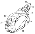
FIG. 10 shows a tool arrangement with a base element in accordance with FIGS. 1 to 4, as well as a chisel holder in accordance with FIGS. 5 to 9, in perspective views from the front; and
FIG. 11 shows the tool arrangement in accordance with FIG. 10, in a perspective view from the rear.
DETAILED DESCRIPTION OF THE INVENTION
A base element 10 of a device for holding a shank chisel 30 is shown in FIGS. 1 to 4. The base element 10 has a fastening section 10.1 with a placement face 12. The placement face 12 has a concavely curved contour, to which the curvature of a cylindrical outer contour of a milling roller is matched. The base element 10 can be placed with the placement face 12 on the milling roller and connected with it, for example welded to it. In a rear area, the fastening section 10.1 has a receiver 13 open toward an underside of the base element 10, so that it can be easily produced, for example by a cut out by machining. In its cross-sectional shape the receiver 13 is laid out so that a nut can be introduced through the open rear of the receiver 13. The circumferential contour of the nut lies, secured against being twisted, in the receiver 13. The threaded portion of the nut is accessible through an opening 14 in a fastening shoulder 15 of the base element 10. In the area of or near the front of the base element 10 the connecting shoulder 10.2 is closed off by a convexly rounded front element 11. As FIG. 2 shows, two plate-shape connecting shoulders 10.2 are formed on the fastening section 10.1. The connecting shoulders 10.2 are arranged in parallel and spaced apart from each other and define a receptacle 10.3 that has been cut into the base element.
Starting from the fastening shoulder 15, the connecting shoulders 10.2 transition via a wall 16 into a convexly arched transition section 17. The base element 10 has a detent 18 adjoining the transition section 17. The detent 18 transitions into a linkage section 19.2 of a convex outer contour, which is embodied or formed as a counter-face 19.1. The linkage section 19 has a form of a partial cylinder, which in this case extends over an arc of 180°. At the front, the linkage section 19 makes a transition by its counter-face 19.1 via a concave indentation into the front element 11.
A chisel holder 20, which can be installed in the above described base element, is shown in FIGS. 5 to 9.
The chisel holder 20 has a holding section 22, into which a cylindrical chisel receiver 28 is inserted. On one side, the chisel receiver 28 makes a transition via an insertion widening 28.1 into a ring-shaped support face 26. The support face 26 encircles the chisel receiver 28. At the end facing away from the support face 26, the chisel receiver 28 terminates in an ejection opening 29. An ejection tool can be inserted into the ejection opening 29 in a customary way for disassembling the shank chisel 30.
A cover 21 extends on both sides of the holding section 22 transversely to the center longitudinal axis of the chisel receiver 28. The covers 21 each enclose a receiver 23. In its front area, the cover 21 is limited by a partially cylindrical, concave contact face 23.4, wherein the curvatures of the contact faces 23.4 are matched to the curvature of the counter-face 19.1 of the base element 10. The chisel holder 20 forms a linkage section 23.1 in the area of the contact face 23.4. Toward the rear of the chisel holder 20, the contact face 23.4 makes a transition into a level seating surface 23.2 that transitions into an inclined wall 23.3. The wall 23.3 is formed by a fixation element 24. As FIG. 6 shows, the fixation element 24 of the chisel holder 20 extends transversely with respect to the center longitudinal axis of the chisel receiver 28 over the entire width of the chisel holder 20. A screw receiver 27 is cut into the fixation element 24. As FIG. 8 shows, the fixation element 24 and a bulge 25 at the front define introduction openings, through which the receivers 23 are accessible.
The manner of proceeding for mounting the chisel holder 20 on the base element 10 is described in view of FIGS. 10 and 11.
Initially, the chisel holder 20 is inserted with a holding shoulder into the receiver 13 in the area between the connecting shoulders 10.2. During this, the connecting shoulders 10.2 engage the receivers 23, until the linkage sections 19 and 23.1 come into engagement. The linkage sections 19 and 23.1 constitute or form a linked seating, around which the chisel holder 20 can be pivoted with respect to the base element 10. In this case, the pivot axis extends through the point of symmetry identified by “M” in FIG. 1. The pivot axis extending through “M” intersects the center longitudinal axis of the chisel receiver 28. The pivot movement of the chisel holder 20 is limited by the inclined wall 23.3 of the base element 10. The wall 16 of the chisel holder 20 strikes against the latter. In this mounting position the bulge 25 engages the indentation 19.1 of the base element 10. The fixation element 24 is at a distance from the fastening shoulder 15. It is then possible to introduce a fastening screw through the screw receiver 27 and the opening 14 aligned with it and to screw it into the nut maintained in the receiver 13. Thus, the chisel holder 20 is fixed in place on the base element 10.
The screw head of the fastening screw is protectively received in a depression 27.1 in the chisel holder 20. Removal of the chisel holder 20 correspondingly occurs in a reversed mounting sequence.
As already stated, a shank chisel 30 with a shank can be inserted into the chisel receiver 28. During this, the shank chisel 30 is maintained in the chisel receiver 28 in a known manner by a clamping sleeve applied to the shank, wherein the shank chisel 30 remains freely rotatable around a center longitudinal axis. The shank chisel 30 has a chisel head with a chisel tip 32 formed on the shank. The chisel head is supported on the support face 26 by a wear-protection element embodied as a perforated disk.

Claims (19)

1. A device for securing a shank chisel, having a base element on which a chisel holder is exchangeably fastened, wherein the chisel holder has a chisel receiver for the shank chisel, the chisel holder has a support face on which the shank chisel can be supported, the chisel holder is connected to the base element by a linked seating, and the chisel holder rests against a counter-face of the base element with a contact face, the device comprising:
in a mounted state of the chisel holder (20) a contact area formed between the contact face (23.4) and the counter-face (19.2) arranged between one of an axis of rotation and a path of rotation of the linked seating and of the support face (26), and in the mounted state of the chisel holder (20) the one of the axis of rotation and the path of rotation intersecting the chisel receiver (28) of the chisel holder (20).
2. The device in accordance with claim 1, wherein the base element (10) has a recessed receiver (10.3) which the chisel holder (20) engages with a holding section (22), and the chisel receiver (28) is arranged at least partially near the recessed receiver (10.3).
3. The device in accordance with claim 2, wherein the chisel holder (20) has a concave linkage section (23.1) which works together with a convex linkage section (19) of the base element (10) for forming the linked seating.
4. The device in accordance with claim 3, wherein the chisel holder (20) has a holding section (22) which forms the chisel receiver (28), and a shoulder is formed transversely with respect to a center longitudinal axis of the chisel receiver (28), which laterally adjoins the holding section (22) and supports the linkage section (23.1).
5. The device in accordance with claim 4, wherein a shoulder is symmetrically arranged on both sides of the holding shoulder (22) with respect to a center longitudinal axis of the chisel receiver (28), each of which has a linkage section (23.1), and the linkage sections (23.1) constitute a common pivot shaft.
6. The device in accordance with claim 5, wherein in the mounted state of the chisel holder (20) the axis of rotation of the linked seating intersects the center longitudinal axis of the chisel receiver (28).
7. The device in accordance with claim 6, wherein the base element (10) has a fastening section (10.1) attachable to a rotatory body of a milling machine, a connecting shoulder (10.2) which supports the linkage section (19) adjoins the fastening section (10.1), and the chisel holder (20) covers the connecting shoulder (10.2) at least partially on a side facing away from the fastening section (10.1) by a cover (21).
8. The device in accordance with claim 7, wherein in the mounted state a seating surface (23.3) of the chisel holder (20) rests against a detent (18) on the base element (10), adjoining a second seating surface (23.2) and facing away from the linked seating, the chisel holder (20) has a fixation element (24) with a screw receiver (27), the fixation element (24) is spaced apart from a fastening shoulder (15) of the base element (10), and the chisel holder (20) is clamped together with the fastening shoulder (15) of the base element (10) by a fastening screw passing through the screw receiver (27).
9. The device in accordance with claim 8, wherein the base element (10) has a receiver near the fastening shoulder (15) in which a nut is received and fixed against relative rotation, and the nut is aligned with an opening (14) of the fastening shoulder (15) and of the screw receiver (27) of the fixation element (24) of the chisel holder (20).
10. The device in accordance with claim 9, wherein the chisel holder (20) has a support face (26) around the chisel receiver (28), on which the shank chisel (30) is supported by a wear-protection element (31), and the linked seating is arranged in a half of an area of the chisel receiver (28) facing the support face (26).
11. A device for securing a shank chisel. having a base element on which a chisel holder is exchangeably fastened. wherein the chisel holder has a chisel receiver for the shank chisel, the chisel holder has a support face on which the shank chisel can be supported, the chisel holder is connected to the base element by a linked seating, and the chisel holder rests against a counter-face of the base element with a contact face, the device comprising:
in a mounted state of the chisel holder (20) a contact area formed between the contact face (23.4) and the counter-face (19.2) arranged between one of an axis of rotation and a path of rotation of the linked seating and of the support face (26), the base element (10) having a recessed receiver (10.3) which the chisel holder (20) engages with a holding section (22), and the chisel receiver (28) arranged at least partially near the recessed receiver (10.3).
12. A device for securing a shank chisel, having a base element on which a chisel holder is exchangeably fastened, wherein the chisel holder has a chisel receiver for the shank chisel, the chisel holder has a support face on which the shank chisel can be supported, the chisel holder is connected to the base element by a linked seating, and the chisel holder rests against a counter-face of the base element with a contact face, the device comprising:
in a mounted state of the chisel holder (20) a contact area formed between the contact face (23.4) and the counter-face (19.2) arranged between one of an axis of rotation and a path of rotation of the linked seating and of the support face (26), and the chisel holder (20) having a concave linkage section (23.1) which works together with a convex linkage section (19) of the base element (10) for forming the linked seating.
13. A device for securing a shank chisel, having a base element on which a chisel holder is exchangeably fastened, wherein the chisel holder has a chisel receiver for the shank chisel, the chisel holder has a support face on which the shank chisel can be supported, the chisel holder is connected to the base element by a linked seating, and the chisel holder rests against a counter-face of the base element with a contact face, the device comprising:
in a mounted state of the chisel holder (20) a contact area formed between the contact face (23.4) and the counter-face (19.2) arranged between one of an axis of rotation and a path of rotation of the linked seating and of the support face (26), the chisel holder (20) having a holding section (22) which forms the chisel receiver (28), and a shoulder formed transversely with respect to a center longitudinal axis of the chisel receiver (28) which laterally adjoins the holding section (22) and supports a linkage section (23.1) of the chisel holder (20).
14. The device in accordance with claim 13, wherein a shoulder is symmetrically arranged on both sides of the holding shoulder (22) with respect to a center longitudinal axis of the chisel receiver (28), each of which has a linkage section (23.1), and the linkage sections (23.1) constitute a common pivot shaft.
15. A device for securing a shank chisel, having a base element on which a chisel holder is exchangeably fastened, wherein the chisel holder has a chisel receiver for the shank chisel, the chisel holder has a support face on which the shank chisel can be supported, the chisel holder is connected to the base element by a linked seating, and the chisel holder rests against a counter-face of the base element with a contact face, the device comprising:
in a mounted state of the chisel holder (20) a contact area formed between the contact face (23.4) and the counter-face (19.2) arranged between one of an axis of rotation and a path of rotation of the linked seating and of the support face (26), and in the mounted state of the chisel holder (20) the axis of rotation of the linked seating intersecting the center longitudinal axis of the chisel receiver (28).
16. A device for securing a shank chisel, having a base element on which a chisel holder is exchangeably fastened, wherein the chisel holder has a chisel receiver for the shank chisel, the chisel holder has a support face on which the shank chisel can be supported, the chisel holder is connected to the base element by a linked seating, and the chisel holder rests against a counter-face of the base element with a contact face, the device comprising:
in a mounted state of the chisel holder (20) a contact area formed between the contact face (23.4) and the counter-face (19.2) arranged between one of an axis of rotation and a path of rotation of the linked seating and of the support face (26), the base element (10) having a fastening section (10.1) attachable to a rotatory body of a milling machine, a connecting shoulder (10.2) which supports the linkage section (19) adjoining the fastening section (10.1), and the chisel holder (20) covering the connecting shoulder (10.2) at least partially on a side facing away from the fastening section (10.1) by a cover (21).
17. A device for securing a shank chisel, having a base element on which a chisel holder is exchangeably fastened, wherein the chisel holder has a chisel receiver for the shank chisel, the chisel holder has a support face on which the shank chisel can be supported, the chisel holder is connected to the base element by a linked seating, and the chisel holder rests against a counter-face of the base element with a contact face, the device comprising:
in a mounted state of the chisel holder (20) a contact area formed between the contact face (23.4) and the counter-face (19.2) arranged between one of an axis of rotation and a path of rotation of the linked seating and of the support face (26), in the mounted state a seating surface (23.3) of the chisel holder (20) resting against a detent (18) on the base element (10), adjoining the seating surface (23.2) and facing away from the linked seating, the chisel holder (20) having a fixation element (24) with a screw receiver (27), the fixation element (24) spaced apart from a fastening shoulder (15) of the base element (10), and the chisel holder (20) clamped together with the fastening shoulder (15) of the base element (10) by a fastening screw passing through the screw receiver (27).
18. The device in accordance with claim 17, wherein the base element (10) has a receiver near a fastening shoulder (15) in which a nut is received and fixed against relative rotation, and the nut is aligned with an opening (14) of the fastening shoulder (15) and of the screw receiver (27) of the fixation element (24) of the chisel holder (20).
19. A device for securing a shank chisel, having a base element on which a chisel holder is exchangeably fastened, wherein the chisel holder has a chisel receiver for the shank chisel, the chisel holder has a support face on which the shank chisel can be supported, the chisel holder is connected to the base element by a linked seating, and the chisel holder rests against a counter-face of the base element with a contact face, the device comprising:
in a mounted state of the chisel holder (20) a contact area formed between the contact face (23.4) and the counter-face (19.2) arranged between one of an axis of rotation and a path of rotation of the linked seating and of the support face (26), the chisel holder (20) having a support face (26) around the chisel receiver (28), on which the shank chisel (30) is supported by a wear-protection element (31), and a linked seating arranged in a half of an area of the chisel receiver (28) facing the support face (26).
US11/578,889 2004-04-19 2005-03-10 Fixing device for a shank chisel Expired - Fee Related US7547075B2 (en)

Applications Claiming Priority (3)

Application Number Priority Date Filing Date Title
DE102004019383.5 2004-04-19
DE102004019383A DE102004019383B4 (en) 2004-04-19 2004-04-19 Device for holding a shank bit
PCT/EP2005/002513 WO2005100748A1 (en) 2004-04-19 2005-03-10 Fixing device for a shank chisel

Publications (2)

Publication Number Publication Date
US20070241605A1 US20070241605A1 (en) 2007-10-18
US7547075B2 true US7547075B2 (en) 2009-06-16

Family

ID=34962449

Family Applications (1)

Application Number Title Priority Date Filing Date
US11/578,889 Expired - Fee Related US7547075B2 (en) 2004-04-19 2005-03-10 Fixing device for a shank chisel

Country Status (6)

Country Link
US (1) US7547075B2 (en)
EP (1) EP1740796B1 (en)
CN (1) CN1942654B (en)
AT (1) ATE553282T1 (en)
DE (1) DE102004019383B4 (en)
WO (1) WO2005100748A1 (en)

Cited By (16)

* Cited by examiner, † Cited by third party
Publication number Priority date Publication date Assignee Title
US20120175939A1 (en) * 2011-01-11 2012-07-12 O'neill Michael L Bit holding system with an opening for removal of broken bits
USD666226S1 (en) 2011-07-04 2012-08-28 Wirtgen Gmbh Chisel holder
USD667854S1 (en) 2011-04-11 2012-09-25 Betek Gmbh & Co. Kg Chisel holder
USD667855S1 (en) 2011-04-11 2012-09-25 Betek Gmbh & Co. Kg Base for a chisel holder
USD669505S1 (en) * 2011-11-23 2012-10-23 Wirtgen Gmbh Chisel holder bar
US9068302B2 (en) 2010-10-06 2015-06-30 Wirtgen Gmbh Mixer bar for a stabilizer/recycler
US9151157B2 (en) 2010-12-03 2015-10-06 Wirtgen Gmbh Chisel holder
US9163502B2 (en) 2010-12-03 2015-10-20 Wirtgen Gmbh Chisel holder, and chisel holder system comprising a chisel holder and a base part
USD746340S1 (en) 2014-04-11 2015-12-29 Vermeer Manufacturing Company Mounting block for reducing elements
USD746878S1 (en) 2014-04-11 2016-01-05 Vermeer Manufacturing Company Mounting block for reducing elements
US9228434B2 (en) 2010-12-03 2016-01-05 Wirtgen Gmbh Chisel holder
US9260965B2 (en) 2011-07-04 2016-02-16 Wirtgen Gmbh Chisel holder for a soil treatment machine
US9267373B2 (en) 2010-12-03 2016-02-23 Wirtgen Gmbh Chisel holder and lower tool part for a chisel holder
US9376911B2 (en) 2010-12-03 2016-06-28 Wirtgen Gmbh Chisel holder, and chisel holder system comprising a chisel holder and a base part
US20180328004A1 (en) * 2015-11-13 2018-11-15 Ihc Holland Ie B.V. Adapter system for cutting tooth
US10378187B2 (en) 2014-03-07 2019-08-13 Vermeer Manufacturing Company Replaceable mounting apparatus for reducing elements

Families Citing this family (6)

* Cited by examiner, † Cited by third party
Publication number Priority date Publication date Assignee Title
DE102004057302B4 (en) * 2004-11-26 2011-01-13 Wirtgen Gmbh toolholders
JP2008540875A (en) * 2005-05-13 2008-11-20 グラウンド アソールト ツールズ ピーティーワイ エルティーディー Cutting tool holder and method of use
DE102008025071A1 (en) * 2008-05-26 2009-12-03 Wirtgen Gmbh Tool for disassembling a chisel
KR101022348B1 (en) 2009-08-28 2011-03-22 삼보중공업(주) Recycling method of tool holder device for crusher
DE102017104651A1 (en) 2017-03-06 2018-09-06 POWER-TECHNOLOGIE GmbH Milling roller and method for milling
DE102017117455A1 (en) 2017-08-02 2019-02-07 POWER-TECHNOLOGIE GmbH Milling roller and method for milling

Citations (8)

* Cited by examiner, † Cited by third party
Publication number Priority date Publication date Assignee Title
EP0129883A2 (en) 1983-06-24 1985-01-02 Siemens Aktiengesellschaft Frontal system for plug-in component boards insertable into frames, and frame for receiving the same
US4609227A (en) 1982-11-13 1986-09-02 Ruhrkohle Ag Cutting-tool mounting for rotary excavating head
EP0200037A2 (en) 1985-05-02 1986-11-05 Kennametal Gmbh Device for supporting a cutting pick and for controlling the supply of spraying fluid to a driving machine
US4915455A (en) 1988-11-09 1990-04-10 Joy Technologies Inc. Miner cutting bit holding apparatus
US5011229A (en) 1988-11-09 1991-04-30 Joy Technologies Inc. Miner cutting bit holding apparatus
DE29510913U1 (en) 1995-07-06 1995-09-28 Wagener, Helmut, 53577 Neustadt Device for holding a milling cutter
DE29711566U1 (en) 1997-07-02 1997-09-04 Wagener, Helmut, 53577 Neustadt Device for holding a milling cutter
US6619756B1 (en) * 1999-02-27 2003-09-16 Wirtgen Gmbh Maschinenbau Chisel holder changing system

Family Cites Families (1)

* Cited by examiner, † Cited by third party
Publication number Priority date Publication date Assignee Title
CN2294333Y (en) * 1997-04-24 1998-10-14 太原矿山机器厂 Cutting edge for coal prodn. machine

Patent Citations (8)

* Cited by examiner, † Cited by third party
Publication number Priority date Publication date Assignee Title
US4609227A (en) 1982-11-13 1986-09-02 Ruhrkohle Ag Cutting-tool mounting for rotary excavating head
EP0129883A2 (en) 1983-06-24 1985-01-02 Siemens Aktiengesellschaft Frontal system for plug-in component boards insertable into frames, and frame for receiving the same
EP0200037A2 (en) 1985-05-02 1986-11-05 Kennametal Gmbh Device for supporting a cutting pick and for controlling the supply of spraying fluid to a driving machine
US4915455A (en) 1988-11-09 1990-04-10 Joy Technologies Inc. Miner cutting bit holding apparatus
US5011229A (en) 1988-11-09 1991-04-30 Joy Technologies Inc. Miner cutting bit holding apparatus
DE29510913U1 (en) 1995-07-06 1995-09-28 Wagener, Helmut, 53577 Neustadt Device for holding a milling cutter
DE29711566U1 (en) 1997-07-02 1997-09-04 Wagener, Helmut, 53577 Neustadt Device for holding a milling cutter
US6619756B1 (en) * 1999-02-27 2003-09-16 Wirtgen Gmbh Maschinenbau Chisel holder changing system

Cited By (26)

* Cited by examiner, † Cited by third party
Publication number Priority date Publication date Assignee Title
US9068302B2 (en) 2010-10-06 2015-06-30 Wirtgen Gmbh Mixer bar for a stabilizer/recycler
US9376911B2 (en) 2010-12-03 2016-06-28 Wirtgen Gmbh Chisel holder, and chisel holder system comprising a chisel holder and a base part
US9151157B2 (en) 2010-12-03 2015-10-06 Wirtgen Gmbh Chisel holder
US9765620B2 (en) 2010-12-03 2017-09-19 Wirtgen Gmbh Chisel holder
US9719348B2 (en) 2010-12-03 2017-08-01 Wirtgen Gmbh Chisel holder
US9267373B2 (en) 2010-12-03 2016-02-23 Wirtgen Gmbh Chisel holder and lower tool part for a chisel holder
US9163502B2 (en) 2010-12-03 2015-10-20 Wirtgen Gmbh Chisel holder, and chisel holder system comprising a chisel holder and a base part
US9228434B2 (en) 2010-12-03 2016-01-05 Wirtgen Gmbh Chisel holder
US20120175939A1 (en) * 2011-01-11 2012-07-12 O'neill Michael L Bit holding system with an opening for removal of broken bits
US8740314B2 (en) * 2011-01-11 2014-06-03 Joy Mm Delaware, Inc. Bit holding system with an opening for removal of broken bits
USD667854S1 (en) 2011-04-11 2012-09-25 Betek Gmbh & Co. Kg Chisel holder
USD667856S1 (en) 2011-04-11 2012-09-25 Betek Gmbh & Co. Kg Chisel holder
USD667855S1 (en) 2011-04-11 2012-09-25 Betek Gmbh & Co. Kg Base for a chisel holder
USD666642S1 (en) 2011-07-04 2012-09-04 Wirtgen Gmbh Chisel holder
USD666226S1 (en) 2011-07-04 2012-08-28 Wirtgen Gmbh Chisel holder
US9260965B2 (en) 2011-07-04 2016-02-16 Wirtgen Gmbh Chisel holder for a soil treatment machine
USD666641S1 (en) 2011-07-04 2012-09-04 Wirtgen Gmbh Chisel holder
USD666643S1 (en) 2011-07-04 2012-09-04 Wirtgen Gmbh Chisel holder
US9739145B2 (en) 2011-07-04 2017-08-22 Wirtgen Gmbh Chisel holder for a soil treatment machine
US10208593B2 (en) 2011-07-04 2019-02-19 Wirtgen Gmbh Chisel holder for a soil treatment machine
USD669505S1 (en) * 2011-11-23 2012-10-23 Wirtgen Gmbh Chisel holder bar
US10378187B2 (en) 2014-03-07 2019-08-13 Vermeer Manufacturing Company Replaceable mounting apparatus for reducing elements
USD746878S1 (en) 2014-04-11 2016-01-05 Vermeer Manufacturing Company Mounting block for reducing elements
USD746340S1 (en) 2014-04-11 2015-12-29 Vermeer Manufacturing Company Mounting block for reducing elements
US20180328004A1 (en) * 2015-11-13 2018-11-15 Ihc Holland Ie B.V. Adapter system for cutting tooth
US10745890B2 (en) * 2015-11-13 2020-08-18 Ihc Holland Ie B.V. Adapter system for cutting tooth

Also Published As

Publication number Publication date
ATE553282T1 (en) 2012-04-15
DE102004019383B4 (en) 2008-06-12
CN1942654B (en) 2011-11-02
EP1740796B1 (en) 2012-04-11
DE102004019383A1 (en) 2005-11-10
EP1740796A1 (en) 2007-01-10
US20070241605A1 (en) 2007-10-18
CN1942654A (en) 2007-04-04
WO2005100748A1 (en) 2005-10-27

Similar Documents

Publication Publication Date Title
US7547075B2 (en) Fixing device for a shank chisel
AU2008317997B2 (en) Shank chisel
AU2010246503B2 (en) Bit holder and base part for receiving a bit holder
TWI509148B (en) Tool holder and tool base for tool holder
KR100922176B1 (en) Base element for Chisel Holder System
US8137034B2 (en) Tool system
AU2010246502B2 (en) Bit holder and base part
US7490912B2 (en) Round shaft chisel
US7112020B2 (en) Cutting tool configured for improved engagement with a tool holder
US7922256B2 (en) Circular-shank tool comprising a tool holder
US7086704B2 (en) Fixing device for a shank chisel
US7451534B2 (en) Valve seat and valve guide machining tool
JP6124857B2 (en) Road cutting machine
US7461903B2 (en) Cutting tool
JP4782450B2 (en) Inner diameter holder and cutting tool
JPH06248611A (en) Cutting chisel device for road cutting machine
US20030213354A1 (en) Cutting tool holder with cutting tool
US6056628A (en) Grinding cup and wear part with vibration dampening means
JPH1177411A (en) Tool holding device
US6431656B1 (en) Processing tool for a road surface processing machine
JP2002160124A (en) Throw-away type reamer
AU2012233012B2 (en) Bit holder and base part for receiving a bit holder
AU2012258452B2 (en) Bit holder and base part
TWI269832B (en) Device for holding a shaft-chisel
KR20100098830A (en) Tool holding device

Legal Events

Date Code Title Description
AS Assignment

Owner name: WIRTGEN GMBH, GERMANY

Free format text: ASSIGNMENT OF ASSIGNORS INTEREST;ASSIGNORS:TEWES, GUNTER;BLENS, JOCHEN;HOLL, BERND;REEL/FRAME:018475/0646;SIGNING DATES FROM 20060926 TO 20061004

STCF Information on status: patent grant

Free format text: PATENTED CASE

FEPP Fee payment procedure

Free format text: PAYOR NUMBER ASSIGNED (ORIGINAL EVENT CODE: ASPN); ENTITY STATUS OF PATENT OWNER: LARGE ENTITY

FPAY Fee payment

Year of fee payment: 4

FPAY Fee payment

Year of fee payment: 8

FEPP Fee payment procedure

Free format text: MAINTENANCE FEE REMINDER MAILED (ORIGINAL EVENT CODE: REM.); ENTITY STATUS OF PATENT OWNER: LARGE ENTITY

LAPS Lapse for failure to pay maintenance fees

Free format text: PATENT EXPIRED FOR FAILURE TO PAY MAINTENANCE FEES (ORIGINAL EVENT CODE: EXP.); ENTITY STATUS OF PATENT OWNER: LARGE ENTITY

STCH Information on status: patent discontinuation

Free format text: PATENT EXPIRED DUE TO NONPAYMENT OF MAINTENANCE FEES UNDER 37 CFR 1.362

FP Lapsed due to failure to pay maintenance fee

Effective date: 20210616