US7541764B2 - Control system for mobile body - Google Patents
Control system for mobile body Download PDFInfo
- Publication number
- US7541764B2 US7541764B2 US10/596,051 US59605104A US7541764B2 US 7541764 B2 US7541764 B2 US 7541764B2 US 59605104 A US59605104 A US 59605104A US 7541764 B2 US7541764 B2 US 7541764B2
- Authority
- US
- United States
- Prior art keywords
- node
- floor reaction
- reaction force
- ground contact
- contact portion
- Prior art date
- Legal status (The legal status is an assumption and is not a legal conclusion. Google has not performed a legal analysis and makes no representation as to the accuracy of the status listed.)
- Expired - Lifetime, expires
Links
Images


Classifications
-
- B—PERFORMING OPERATIONS; TRANSPORTING
- B25—HAND TOOLS; PORTABLE POWER-DRIVEN TOOLS; MANIPULATORS
- B25J—MANIPULATORS; CHAMBERS PROVIDED WITH MANIPULATION DEVICES
- B25J13/00—Controls for manipulators
-
- B—PERFORMING OPERATIONS; TRANSPORTING
- B25—HAND TOOLS; PORTABLE POWER-DRIVEN TOOLS; MANIPULATORS
- B25J—MANIPULATORS; CHAMBERS PROVIDED WITH MANIPULATION DEVICES
- B25J13/00—Controls for manipulators
- B25J13/08—Controls for manipulators by means of sensing devices, e.g. viewing or touching devices
- B25J13/085—Force or torque sensors
-
- B—PERFORMING OPERATIONS; TRANSPORTING
- B25—HAND TOOLS; PORTABLE POWER-DRIVEN TOOLS; MANIPULATORS
- B25J—MANIPULATORS; CHAMBERS PROVIDED WITH MANIPULATION DEVICES
- B25J5/00—Manipulators mounted on wheels or on carriages
-
- B—PERFORMING OPERATIONS; TRANSPORTING
- B62—LAND VEHICLES FOR TRAVELLING OTHERWISE THAN ON RAILS
- B62D—MOTOR VEHICLES; TRAILERS
- B62D57/00—Vehicles characterised by having other propulsion or other ground- engaging means than wheels or endless track, alone or in addition to wheels or endless track
- B62D57/02—Vehicles characterised by having other propulsion or other ground- engaging means than wheels or endless track, alone or in addition to wheels or endless track with ground-engaging propulsion means, e.g. walking members
- B62D57/032—Vehicles characterised by having other propulsion or other ground- engaging means than wheels or endless track, alone or in addition to wheels or endless track with ground-engaging propulsion means, e.g. walking members with alternately or sequentially lifted supporting base and legs; with alternately or sequentially lifted feet or skid
Definitions
- the present invention relates to a control system for a mobile robot, such as a bipedal mobile robot and, more specifically, to a system for controlling a floor reaction force (external force) acting on the mobile robot in a case where a portion of the robot, such as a knee, an elbow, or a trunk, other than a distal portion of a leg or an arm of the robot is brought into contact with the ground or in a similar case.
- a portion of the robot such as a knee, an elbow, or a trunk, other than a distal portion of a leg or an arm of the robot is brought into contact with the ground or in a similar case.
- Patent Document 1 Japanese Unexamined Patent Application Publication No. H5-305585
- Patent Document 2 Japanese Unexamined Patent Application Publication No. H10-277969
- Patent Document 3 Japanese Unexamined Patent Application Publication No. 2001-322076
- the present invention has been made with a view of the background described above, and it is an object thereof to provide a control system for a mobile robot that properly controls not only external forces acting on the distal portions of legs and arms of the robot but also external forces acting on portions other than the distal portions of the legs and arms in a state wherein the portions of a mobile robot, such as knees, elbows, the trunk, and buttocks, other than the legs and arms are subjected to external forces when they come in contact with a floor or an object considered as an extension of the floor, thus making it possible to maintain stable postures of the mobile robot.
- a control system for a legged mobile robot comprising a base body, a plurality of link mechanisms that are connected to the base body and that come in contact with externals to move the base body, and a plurality of joints provided between the base body and the distal portions of the link mechanisms to make the distal portions of the link mechanisms movable with respect to the base body, the legged mobile robot being able to be operated to a specific motion posture in which the robot is in contact with an external at a predetermined portion or portions between the distal portion or portions of one or more specific link mechanisms among the plurality of link mechanisms and the base body, the control system comprising:
- an external force detecting means for detecting or estimating an external force acting on the predetermined portion in the specific motion posture
- a desired external force determining means for determining a desired external force, which is a desired value of the external force on the predetermined portion in the specific motion posture
- a joint displacement controlling means for controlling the displacement of at least a joint existing between the predetermined portion and the base body such that the detected or estimated external force approximates the desired external force.
- the predetermined portion comes in contact with an external in the specific motion posture.
- This predetermined portion is the portion provided on the specific link mechanism at between the base body and the distal portion of the specific link mechanism, an external force acting on the predetermined portion being detected or estimated by the external force detecting means. Then, the displacement of the joint existing at least between the predetermined portion and the base body is controlled such that the detected or estimated external force approximates a desired external force determined by the desired external force determining means, making it possible to properly control the external force acting on the predetermined portion. As a result, the stability of a posture of the robot can be maintained.
- the specific link mechanism is, for example, a leg body (a second invention).
- the predetermined portion is an intermediate portion (e.g., a knee) between the distal portion of the leg body and the base body.
- the link mechanisms provided on the robot may include arm bodies rather than being limited to leg bodies.
- the specific link mechanisms may be only leg bodies or arm bodies, or they may include both leg bodies and arm bodies.
- the specific link mechanisms are leg bodies extended from buttocks connected to the base body through the intermediary of joints, and the predetermined portion is the buttocks (a third invention).
- the external force acting on the buttocks can be controlled so as to control the posture of the robot (particularly the posture of the base body, such as the body) to a proper stable posture.
- the aforesaid first invention (or the first to the third inventions) comprises an actual posture detecting means for detecting the actual posture of a second predetermined portion, such as the base body, of the mobile robot; and a desired motion determining means for determining a desired posture of the second predetermined portion, wherein the desired external force determining means determines the desired external force on the basis of at least the difference between the actual posture and the desired posture of the second predetermined portion (a fourth invention).
- the external force acting on the predetermined portion can be controlled so as to restore the actual posture of the second predetermined portion (e.g., the base body) to a predetermined desired posture, thus allowing the stability of a posture of the robot to be enhanced.
- the second predetermined portion e.g., the base body
- the aforesaid first invention comprises an actual posture detecting means for detecting the actual posture of a second predetermined portion, such as the base body, of the mobile robot; and a desired motion determining means for determining the desired posture of the second predetermined portion
- the joint controlling means comprises a means for determining the manipulated variable of an external force on the basis of the difference between the actual posture and the desired posture of the second predetermined portion, and the displacement of the joint is controlled such that the detected or estimated external force approximates the resultant force of the desired external force and the manipulated variable of the external force (a fifth invention).
- the displacement of a joint is controlled such that the external force acting on the predetermined portion approximates a desired external force and also the actual posture of the second predetermined portion (e.g., the base body) approximates a desired posture, thus making it possible to stabilize a posture of the robot and also to properly control an external force acting on a predetermined portion.
- the second predetermined portion in the fourth invention and the fifth invention may be identical to a predetermined portion that comes in contact with an external in the aforesaid specific motion posture.
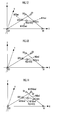
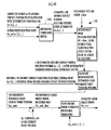
- FIG. 1 is an overall external view of a robot in accordance with a first reference example and a second reference example related to the present invention
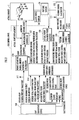
- FIG. 2 is a block diagram showing the functional construction of a control system of the first reference example
- FIGS. 4( a ) to ( c ) are diagrams for explaining an operation of the robot (four-legged robot) of the first reference example
- FIGS. 5( a ) to ( c ) are graphs showing setting examples of weights in the first reference example
- FIG. 5( d ) is a graph showing a setting example of a ZMP (desired total floor reaction force central point) in the first reference example.
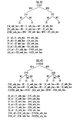
- FIG. 6 is a diagram showing the hierarchical structure of nodes in the first reference example
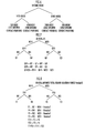
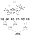
- FIG. 7 is a diagram showing a relationship between desired node floor reaction force central points and weights
- FIG. 8 is a diagram showing a relationship between desired node floor reaction forces and weights.
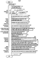
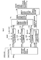
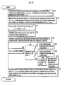
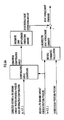
- FIG. 9 is a flowchart showing main routine processing of the control system of the first reference example.
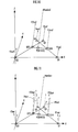
- FIG. 10 to FIG. 14 are diagrams illustrating desired node floor reaction force translational force components, actual node floor reaction force translational force components, actual node floor reaction force moments, compensating total floor reaction force moments, and node compensating floor reaction force moments, respectively, of a robot (four-legged robot) of the first reference example.
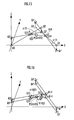
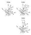
- FIG. 15 and FIG. 16 are diagrams for explaining position corrections based on node compensating angles (compliance operation) in the first reference example
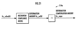
- FIG. 17 to FIG. 21 are block diagrams showing the functional constructions of a hierarchical compliance operation determiner, a compensating total floor reaction force moment distributor, a ⁇ 1423 determiner (compensating angle determiner), a ⁇ 14 determiner (compensating angle determiner), and a mechanism deformation compensation amount calculator, respectively, in the first reference example,
- FIG. 22 is a flowchart showing the processing for determining compensating angles
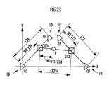
- FIG. 23 is a diagram for explaining another example of a hierarchical structure related to the robot of the first reference example.
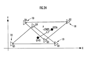
- FIG. 24 is a diagram for explaining the hierarchical structure of a robot (six-legged robot) of a second reference example
- FIG. 25 is a block diagram showing the functional construction of a hierarchical compliance operation determiner in the second reference example
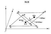
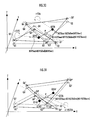
- FIG. 26 to FIG. 28 are diagrams respectively illustrating the translational force components of desired node floor reaction forces, the translational force components of actual node floor reaction forces, and actual node floor reaction force moments of the robot (six-legged robot) of the second reference example,
- FIGS. 29( a ) and ( b ) are diagrams for explaining the technique for setting a node compensating floor reaction force moment in the second reference example.
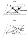
- FIG. 30 and FIG. 31 are diagrams for explaining a position correction based on a node compensating angle (compliance operation) in the second reference example.
- FIG. 32 and FIG. 33 are block diagrams showing the functions of a ⁇ 145236 determiner (compensating angle determiner) and a ⁇ 145 determiner (compensating angle determiner), respectively, in the second reference example, and
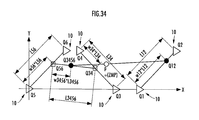
- FIG. 34 is a diagram for explaining another example of a hierarchical structure related to the robot of the second reference example.
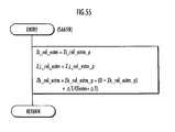
- FIG. 35 is a block diagram showing the functional construction of a hierarchical compliance operation determiner in a third reference example
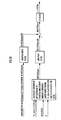
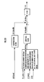
- FIG. 36 is a flowchart showing main routine processing of a control system in the third reference example.
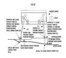
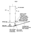
- FIG. 37 to FIG. 39 are diagrams for explaining concepts and terms in the third reference example.
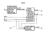
- FIG. 40 is a block diagram showing the function of a floor configuration estimator in the third reference example.
- FIG. 41 is a flowchart showing the processing of a floor height error estimation processing subroutine in FIG. 40 .
- FIG. 42 and FIG. 43 are diagrams for explaining the processing for hierarchical relativization in a four-legged robot and a six-legged robot, respectively.
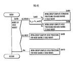
- FIG. 44 is a diagram showing examples of setting request modes of nodes related to the estimation of a floor configuration.
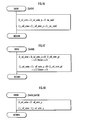
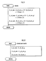
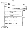
- FIG. 45 to FIG. 55 are flowcharts showing the processing for estimating a floor configuration.
- FIG. 56 is a block diagram showing the functions of a floor configuration estimator in a fourth reference example.
- FIG. 57 is a block diagram showing the functions of a floor configuration estimator in a fifth reference example.
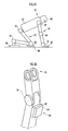
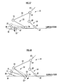
- FIG. 58 and FIG. 59 are diagrams showing a state wherein a robot (two-legged mobile robot) in a first embodiment of the present invention is kneeling,
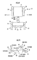
- FIG. 60 is a diagram showing the construction of a floor reaction force sensor of a knee of the robot in the first embodiment
- FIG. 61 is a diagram showing a hierarchical structure of nodes in the first embodiment.
- FIG. 62 is a block diagram showing the functional construction of a hierarchical compliance operation determiner in the first embodiment.
- FIGS. 63( a ) to ( c ) are diagrams for explaining a technique for correcting the posture of the body of the robot in the first embodiment
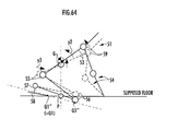
- FIG. 64 is a diagram for explaining a technique for correcting the position/posture of the body of the robot in the first embodiment.
- FIG. 65 is a block diagram showing the functions of an inverse kinematics calculator in the first embodiment.
- FIG. 66 is a block diagram showing the functions of an inverse kinematics calculator in a second embodiment
- FIG. 67 and FIG. 68 are diagrams for explaining a technique for correcting the posture of a robot in the second embodiment.
- FIG. 69 is a diagram showing the construction of a robot in a third embodiment.
- FIG. 70 is a diagram showing a hierarchical structure of nodes in the third embodiment.
- the ground contact portion a portion of a legged mobile robot that comes in contact with a floor and receives a reaction force in a predetermined operation of the robot is referred to as “the ground contact portion.”
- floor does not simply refers to a floor (or the ground) in a usual sense, but “floor” also includes an object with which the robot comes in contact and which receives a reaction force in its motion, such as a chair (a chair on which the robot sits) fixed to the floor (or the ground).
- a chair a chair on which the robot sits
- the waist of the robot will correspond to the ground contact portion.
- the distal portion (foot or the like) of each leg will of course correspond to the ground contact portion.
- ground contact portions even if ground contact portions are distributed such that they are separated at a plurality of locations on the same link (a part corresponding to a single rigid body)(if a plurality of portions separated from each other on the same link is in contact with the ground), that is, even if a plurality of ground contact surfaces are not connected on the same link, these will be put together and defined as one ground contact portion. For instance, if the ground contact portion provided with four spike pins comes in contact with the ground through the intermediary of the spike pins, then the individual ground contact surfaces of the four spike pins will be put together and regarded as one ground contact portion. However, it is not always required to put the ground contact surfaces together into one.
- a ground contact portion floor reaction force refers to a floor reaction force acting on a ground contact portion, and the floor reaction force acting on an n-th ground contact portion, in particular, is referred to as the n-th ground contact portion floor reaction force.
- the total floor reaction force is the resultant force of the floor reaction forces acting on all ground contact portions.
- the floor reaction force central point is the point of action at which the horizontal component of a moment generated by a floor reaction force at that point is zero.
- a floor reaction force such as a ground contact portion floor reaction force or a total floor reaction force, is usually expressed by a set of the point of action of a force and a translational force and moment applied to that point of action.
- a floor reaction force that uses, as the point of action, a point at which a moment component (the horizontal component of a moment) except a component about a vertical axis (vertical component) is zero.
- the point of action in this expression is referred to as a floor reaction force central point in the present description.
- a floor reaction force central point may be defined as a point at which the floor surface parallel component (the component parallel to a floor surface) of a moment generated by a floor reaction force at that point is zero.
- floor surface may alternatively be a virtual floor surface (a floor surface assumed on a desired gait and it does not necessarily coincide with an actual floor surface) described in Japanese Unexamined Patent Application Publication No. H5-318340 previously proposed by the present applicant.
- the floor reaction force central point of a ground contact portion is usually set on the ground contact surface thereof (the surface in contact with a floor) if the ground contact portion is in contact with the ground.
- the ground contact portion floor reaction force while the ground contact portion is moving in the air is always zero, so that a moment horizontal component of the ground contact portion floor reaction force will be zero at any point of action.
- the floor reaction force central point can be arbitrarily set.
- a desired floor reaction force central point moves in continuity.
- a floor reaction force central point of a ground contact portion floor reaction force is defined as the point of action that moves together with the ground contact portion when the ground contact portion moves in the air.
- the compliance control operation in the compliance control operation wherein the position/posture of each ground contact portion are corrected on the basis of at least an actual floor reaction force (a floor reaction force actually acting on a robot), the compliance control operation is not simply performed on each of ground contact portions irrelevantly (independently) from each other.
- the embodiments of the present description are characterized in that ground contact portion are classified into a tree structure and operations for correcting the positions/postures of ground contact portions are determined on the basis of at least an actual floor reaction force acting on each group that has been classified (the actual floor reaction forces acting on all ground contact portions included in each group or the resultant force thereof).
- sorting by the tree structure may be referred to as “hierarchization.”
- “desired” will be attached to the beginning of the names of variables.
- “actual” will be attached to the beginning of the names of variables.
- the above “actual floor reaction force” is an example thereof.
- the targets of the total floor reaction forces (the resultant force of the actual floor reaction forces acting on all ground contact portions of the robot) in the compliance control (floor reaction force control) to be discussed later will be referred to as desired total floor reaction forces.
- the point at which the moment horizontal component of a desired total floor reaction force is zero will be referred to as a desired total floor reaction force central point.
- the point on a floor surface at which the moment horizontal component of the resultant force of an inertial force generated by a motion of a desired gait of a mobile robot (the motion of each portion of the robot in a desired gait) and the gravity acting on the robot becomes zero will be referred to as a desired ZMP.
- the motion of a desired gait is determined by the time series of the desired position/posture of each portion of the robot in the desired gait, so that the time series of the desired position/posture of the portion will be generically referred to as a motion of a desired gait or a desired motion.
- desired motions may be described by expressions that are different from the desired motions defined as described above. For example, a set of the time series of the desired displacements of joints of a robot and the time series of the desired position/posture of a particular portion, such as a base body, may be used as a desired motion.
- a desired total floor reaction force is usually a total floor reaction force that dynamically balances with the motion patter of a desired gait (the time-series pattern of a desired motion).
- a desired total floor reaction force central point usually agrees with a desired ZMP.
- a desired total floor reaction force central point and a desired ZMP will be used without discriminating them in many cases.
- a desired total floor reaction force central point and a desired ZMP do not necessarily agree with each other.
- the term, desired ZMP will be used in some cases, but there will be some places where the term, desired total floor reaction force central point, should be used to be precise.
- reaction force an external force
- the reaction force (the external force) other than a floor reaction force may be referred to as, for example, a desired object reaction force, and the definition of a desired ZMP described above may be expanded as follows.
- the resultant force of the inertial force generated by a motion pattern of a desired gait of a robot, the gravity acting on the robot, and a desired object reaction force may be dynamically determined, and if the moment generated at a certain point on a floor surface by the resultant force is zero except for a component about a vertical axis, then the point may be defined anew as a desired ZMP. However, if a desired object reaction force is taken as one form of a floor reaction force, then the definition of a desired ZMP may be the same as the definition previously described.
- FIG. 1 is an external view of a general multi-legged mobile robot (legged mobile robot) according to first and second reference examples.
- FIG. 1 shows that the robot 1 has six legs (leg bodies), namely, a first leg # 1 to a sixth leg # 6 ; however, it does not have the fifth leg # 5 and the sixth leg # 6 in the first reference example.
- the robot 1 is a four-legged robot having four legs (leg bodies), the first leg # 1 to the fourth leg # 4 .
- the components of the robot 1 according to the second reference example are shown by parenthesized reference numerals.
- two legs are extended from the right side of a body 24 , which is the base body of the robot 1 , such that they are arranged side by side in the longitudinal direction, and in the same manner, two legs (the second leg # 2 and the fourth leg # 4 ) are extended from the left side of the body 24 such that they are arranged side by side in the longitudinal direction.
- a discoid ground contact portion 10 is attached to the distal portion of each of the legs # 1 to # 4 through the intermediary of a spherical joint 12 , which is a free joint.
- the ground contact portions 10 need to be discriminated among the legs # 1 to # 4 , they will be referred to as the first ground contact portion, the second ground contact portion, the third ground contact portion, and the fourth ground contact portion.
- Each ground contact portion 10 is engaged with the spherical joint 12 such that its central point agrees with the central point of the spherical joint 12 and that a floor reaction force moment (the moment component of a floor reaction force) will not act on the central point of the ground contact portion 10 (strictly speaking, the spherical joint 12 ). This means that the floor reaction force moment (actual floor reaction force moment) at the central point of the ground contact portion 10 will be always zero.
- each of the legs # 1 to # 4 is provided with joints 14 and 15 at a portion adjacent to the body 24 of the robot 1 and at an intermediate portion, respectively, and a compliance mechanism 42 composed of an elastic member, such as a spring, and a six-axis force sensor 34 serving as a floor reaction force detecting means (external force detecting means) for detecting an actual floor reaction force acting on the ground contact portion 10 are provided in the vicinity of the distal portion of each of the legs # 1 to # 4 (a portion of the link connecting the spherical joint 12 and the joint 14 , the portion being adjacent to the spherical joint 12 ).
- the joints 14 can be rotated about two axes, while the joints 15 can be rotated about one axis.
- the bottom surfaces of the ground contact portions may be provided with elastic members made of sponge, rubber or the like serving as compliance mechanisms.
- the displacement operation (the rotational operation about each axis) of each of the joints 14 and 15 is performed by an actuator, such as an electric motor, which is not shown.
- an actual joint displacement, which is the actual displacement amount (the angle of rotation about each axis), of each of the joints 14 and 15 is detected by a sensor, such as a rotary encoder, which is not shown.
- the six-axis force sensor 34 is capable of detecting the translational forces in the directions of three axes and the moments about three axes; however, in the robot 1 in the first reference example, no actual floor reaction force moment acts on the central points of the ground contact portions 10 , as described above.
- three-axis force sensors that detect the translational forces in the directions of three axes or force sensors that detect only the vertical components of the translational forces of actual floor reaction forces may be used in place of the six-axis force sensors 34 .
- the body 24 incorporates a control system 50 constructed of an electronic circuit unit that includes a microcomputer, an actuator drive circuit, etc., a posture sensor 36 for detecting the postures of the body 24 , and a power source not shown (a secondary battery, a capacitor, or the like).
- the posture sensor 36 is constructed of, for example, an acceleration sensor and a gyro sensor.
- “posture” generally means a spatial orientation (however, “the posture” of the entire robot means an instantaneous value of a motion of the robot).
- the posture sensor 36 detects the posture inclinations (inclination angles) of the postures of the body 24 in, for example, the pitch directions and roll directions in relation to the vertical direction.
- the posture sensor 36 functions as an actual posture inclination detecting means for detecting actual posture inclinations of the body 24 .
- the rotational angles of the body 24 in the yaw direction may be also detected by the posture sensor 36 .
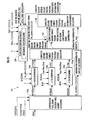
- FIG. 2 is a block diagram showing the functional construction and operations of the control system 50 .
- the actual robot 1 shown in FIG. 2 is the robot 1 shown in FIG. 1 from which the control system 50 , the posture sensor 36 , and the six-axis force sensor 34 have been removed.
- a predetermined coordinate system (XYZ coordinate system) fixed to a floor, in which the approximately front direction of the robot 1 is defined as X axis, approximately left side direction thereof is defined as Y axis, and the upward direction thereof is defined as Z axis, as shown in FIG.
- a supporting leg coordinate system or “a global coordinate system.”
- positions, postures, translational forces and moments will be expressed in terms of the sets of coordinate components of the supporting leg coordinate system (the global coordinate system) unless otherwise specified.
- the origin of the supporting leg coordinate system does not have to be steadily fixed at a single point; the position of the origin with respect to a floor may be changed while the robot 1 is traveling. For example, the position of the origin of the supporting leg coordinate system (the global coordinate system) may be changed each time a predetermined leg of the robot 1 lands.
- the control system 50 is provided with a gait generating device 100 , a desired floor reaction force distributor 102 , a robot geometric model (inverse kinematics calculator) 110 , a hierarchical compliance operation determiner 114 , a displacement controller 112 , an actual floor reaction force detector 108 , a posture error calculator 103 , and a posture stabilization control calculator 104 as its functional components (functional means).
- a gait generating device 100 As shown in FIG. 2 , the control system 50 is provided with a gait generating device 100 , a desired floor reaction force distributor 102 , a robot geometric model (inverse kinematics calculator) 110 , a hierarchical compliance operation determiner 114 , a displacement controller 112 , an actual floor reaction force detector 108 , a posture error calculator 103 , and a posture stabilization control calculator 104 as its functional components (functional means).
- the following will explain the overviews of the components of the control system 50 .
- the gait generating device 100 has a function as a desired gait determining means or a desired motion determining means, and generates (determines) and outputs a desired gait that specifies an operation of the robot 1 .
- a desired gait is formed of the trajectory of a desired motion of the robot (the time series of the desired position/posture of each portion of the robot) and the trajectory of a desired floor reaction force (the time series of a set of the desired position of the action point of a reaction force received by the robot from a floor and the desired values of a translational force and moment applied to the action point).
- “trajectory” means a time-series pattern (temporal change pattern).
- the trajectory of a desired motion output by the gait generating device 100 is constructed of a desired ground contact portion trajectory, which is the trajectory of the desired values of the position and the posture of each ground contact portion 10 of the robot 1 , and a desired body position/posture trajectory, which is the trajectory of the desired values of the position and the posture of the body 24 of the robot 1 .
- the trajectory of a desired floor reaction force output by the gait generating device 100 is formed of a desired total floor reaction force central point trajectory, which is the trajectory of a desired position of the total floor reaction force central point of the robot 1 , and a desired total floor reaction force trajectory, which is the trajectory of a desired value of a total floor reaction force that uses the above desired total floor reaction force central point as an action point.
- a desired total floor reaction force central point trajectory is regarded as identical to a desired ZMP trajectory, which is the trajectory of a desired position of ZMP.
- each ground contact portion 10 is the position of a certain representative point of the ground contact portion 10 , and the representative point is, for example, the projected point obtained by projecting, in the vertical direction, the central point of each ground contact portion 10 (the central point of the spherical joint 12 ) onto the ground contact surface (bottom surface) of the ground contact portion 10 , or the central point of the ground contact portion 10 (the central point of the spherical joint 12 ).
- the position of the representative point of each ground contact portion 10 will be referred to simply as the ground contact portion position.
- the trajectory of a desired value of the ground contact portion position (a desired ground contact portion position trajectory) is included in the aforesaid desired ground contact portion trajectory determined by the gait generating device 100 .
- the ground contact portions 10 are engaged with the spherical joints 12 , which are free joints, so that the postures of the ground contact portions 10 cannot be controlled. Therefore, in the present reference example, the gait generating device 100 does not actually generate the trajectories of desired postures of the ground contact portions 10 (does not have to generate them). In the present reference example, therefore, the aforesaid desired ground contact portion trajectory means the same as a desired ground contact portion position trajectory.
- ground contact portion position/posture will be frequently used to generally consider the aforesaid case, the term substantially meaning “ground contact portion position” in the present reference example.
- a desired ground contact portion trajectory (a desired ground contact portion position trajectory) and a desired total floor reaction force central point trajectory will be explained more specifically.
- a travel of the robot 1 is accomplished by carrying out the motions of the legs # 1 to # 4 by causing a pair of legs, which are to be free legs, to leave a floor and move in the air and then land at a desired position by repeating, in order, a period during which the pair of the first leg # 1 and the fourth leg # 4 out of the legs # 1 to # 4 is a pair of supporting legs, while the pair of the second leg # 2 and the third leg # 3 is a pair of free legs, a period during which all legs # 1 to # 4 are supporting legs, and a period during which the pair of the first leg # 1 and the fourth leg # 4 is a pair of free legs, while the pair of the second leg # 2 and the third leg # 3 is a pair of supporting legs.
- a supporting leg is a leg that is in contact with the ground to support the self-weight of the robot 1 (a leg to be subject to a floor reaction force that is not zero), and a free leg is a non-supporting leg.
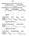
- FIG. 3( a ) to FIG. 3( c ) and FIG. 4( a ) to FIG. 4( c ) show the desired ground contact portion positions (more specifically, the positions on a horizontal plane (XY plane)) of the distal ends of the legs # 1 to # 4 during the aforesaid travel of the robot 1 in time series in sequence (in the sequence of time t 1 to t 6 ).
- the triangles corresponding to reference characters Q 1 to Q 4 in these figures indicate the desired ground contact portion positions of the first to the fourth ground contact portions 10 , respectively (the positions of the aforesaid representative points of the first to the fourth ground contact portions 10 on a horizontal plane (XY plane)).
- the triangles with the reference characters Q 1 to Q 4 in FIG. 3 and FIG. 4 indicate the positions of desired node floor reaction force central points (desired ground contact portion floor reaction force central points) to be discussed later, which are related to the ground contact portions 10 .
- the triangles corresponding to the reference characters Q 1 , Q 2 , Q 3 and Q 4 in FIG. 3 and FIG. 4 denote the desired node floor reaction force central points, which will be discussed later, of the first to the fourth ground contact portions 10 , respectively, and also denote the positions of the first to the fourth ground contact portions 10 , respectively.
- FIG. 3( a ) shows the desired ground contact portion positions of the ground contact portions 10 at the moment (time t 1 ) when the pair of the first leg # 1 and the fourth leg # 4 as free legs are landed, the pair of the second leg # 2 and the third leg # 3 being supporting legs
- FIG. 3( b ) shows the desired ground contact portion positions at time t 2 in a state wherein all the legs # 1 to # 4 are supporting legs
- FIG. 3( c ) shows the desired ground contact portion positions at time t 3 immediately before the pair of the second leg # 2 and the third leg # 3 as free legs is separated from a floor (lifted into the air), the pair of the first leg # 1 and the fourth leg # 4 being supporting legs.
- FIG. 3( a ) shows the desired ground contact portion positions of the ground contact portions 10 at the moment (time t 1 ) when the pair of the first leg # 1 and the fourth leg # 4 as free legs are landed, the pair of the second leg # 2 and the third leg # 3 being supporting legs
- FIG. 4( a ) shows the desired ground contact portion positions at time t 4 in a state wherein the pair of the second leg # 2 and the third leg # 3 as free legs is lifted into the air, the pair of the first leg # 1 and the fourth leg # 4 being supporting legs
- FIG. 4( b ) shows the desired ground contact portion positions at the moment (time t 5 ) when the pair of the second leg # 2 and the third leg # 3 as free legs are landed, the pair of the first leg # 1 and the fourth leg # 4 being supporting legs
- FIG. 4( b ) shows the desired ground contact portion positions at the moment (time t 5 ) when the pair of the second leg # 2 and the third leg # 3 as free legs are landed, the pair of the first leg # 1 and the fourth leg # 4 being supporting legs
- FIG. 4 ( c ) shows the desired ground contact portion positions at time t 6 immediately before the pair of the first leg # 1 and the fourth leg # 4 as free legs is separated from a floor, the pair of the second leg # 2 and the third leg # 3 being supporting legs.
- the desired ground contact portion positions of the second leg # 2 and the third leg # 3 which are free legs, are indicated by dashed-line triangles.
- the trajectory of the positions of the ground contact portions 10 of free legs in the vertical direction are determined such that they rise from a floor surface to a predetermined height and then lower to land again.
- Points P in these FIG. 3 and FIG. 4 indicate desired total floor reaction force central points (desired ZMPs).
- the desired total floor reaction force central point trajectories are determined such that they continuously move while existing in a range in which ZMPs may exist (a region on a floor surface corresponding to a so-called supporting polygon) at positions not excessively close to the boundaries of the range (e.g., at an approximately central position of the range wherein a ZMP may exist).
- a range in which ZMPs may exist a region on a floor surface corresponding to a so-called supporting polygon
- a desired total floor reaction force central point is set on a segment connecting the representative points of the ground contact portions 10 and 10 of those legs such that it is not excessively close to an end point of the segment.
- a desired total floor reaction force central point is set within a polygon having the representative points of all ground contact portions 10 as its apex angles such that it is not excessively close to a boundary of the polygon.
- FIGS. 5( a ) to ( c ) are graphs illustrating setting examples of weights, which will be discussed later.
- a desired body position/posture trajectory determined by the gait generating device 100 is determined using at least a dynamic model or the like of the robot 1 such that the horizontal component of a moment generated about a desired ZMP by the resultant force of the inertial force generated by a desired motion of the robot 1 and the gravity acting on the robot 1 becomes zero.
- the body position is the position of a certain representative point of the body 24 .
- a desired total floor reaction force determined by the gait generating device 100 is constructed of the desired values of the translational force and the moment acting on a desired total floor reaction force central point, and it is determined such that it balances with the resultant force of the inertial force generated by a desired motion of the robot 1 and the gravity acting on the robot 1 at a desired total floor reaction force central point in the present reference example.
- the moment horizontal component of the desired total floor reaction force about the desired total floor reaction force central point is zero.
- the desired ground contact portion trajectory determined by the gait generating device 100 (the desired ground contact portion position trajectory) is corrected by a hierarchical compliance operation determiner 114 , which will be discussed later.
- the desired floor reaction force distributor 102 groups (that is, hierarchizes) the first to the fourth ground contact portions 10 of the robot 1 into a tree structure, and associates the nodes of the tree structure with each of the hierarchized groups.
- the nodes may be expressed by replacing them by the groups.
- Each node is a group constructed of one or more ground contact portions 10 .
- the first to the fourth nodes are nodes that are constructed of the first, the second, the third, and the fourth ground contact portions 10 , respectively, the 14th node is a node constructed of the first ground contact portion 10 and the fourth ground contact portion 10 , the 23rd node is a node constructed of the second ground contact portion 10 and the third ground contact portion 10 , and the 1423rd node is the node constructed of all the ground contact portions 10 .
- a node having no child node is referred to as a leaf node
- a node having no parent node is referred to as a root node.
- the 1423rd node is a root node.
- leaf nodes will be assigned the same numbers (1, 2, 3, . . . ) as those of the ground contact portions (or legs) associated therewith, while nodes other than the leaf nodes will be assigned with numbers that are greater than those of the leaf nodes.
- the nodes other than the leaf nodes and the root node will be referred to as intermediate nodes.
- the intermediate nodes are the 14th node and the 23rd node.
- Input to the desired floor reaction force distributor 102 are a desired total floor reaction force central point trajectory, a desired total floor reaction force trajectory, and a desired ground contact portion trajectory out of a desired gait determined by the gait generating device 100 .
- the gait parameters (the estimated landing position, an estimated landing time, etc. of the ground contact portion 10 of a free leg of the robot 1 ) used by the gait generating device 100 to determine the desired gait may be also input to the desired floor reaction force distributor 102 .
- FIG. 3( b ) shows a relationship between Qn and Wn in a state illustrated in the figure
- FIGS. 5( a ) to ( c ) show setting examples of Wn
- FIG. 7 shows a relationship between weights and desired node floor reaction force central points.
- a weight W 1423 of the root node is set to “1” for the sake of convenience in order to maintain the uniformity of expressions.
- the desired node floor reaction force central point of a leaf node may be referred to as a desired ground contact portion floor reaction force central point in some cases.
- a segment that connects arbitrary two points A and B or the length thereof will be denoted as AB.
- an operator “*” means multiplication for a pair of scalar and scalar or a pair of scalar and vector, while it means an outer product (vector product) for a pair of vector and vector.
- the above expressions 1 to 3 mean that the position of a desired node floor reaction force central point of each node having child nodes (that is, each node that is not a leaf node) is set to a weighted average position of the position of the desired node floor reaction force central points of the child nodes of the node by using a predetermined nonnegative weight.
- L 23 , L 14 and L 1423 in FIG. 3( b ) denote the lengths of segments Q 2 Q 3 , Q 1 Q 4 and Q 23 Q 14 , respectively.
- the desired node floor reaction force central points Q 14 and Q 23 of the intermediate nodes move as the ground contact portions 10 move, as shown in time series in FIG. 3( a ) to FIG. 3( c ) and FIG. 4( a ) to FIG. 4( c ).
- the desired floor reaction force distributor 102 outputs the desired node floor reaction force central point of each node determined as described above.
- the desired floor reaction force central point of the root node is the same as the desired total floor reaction force central point determined by the gait generating device 100 , so that it does not have to be output from the desired floor reaction force distributor 102 .
- the desired floor reaction force distributor 102 determines and outputs a desired node floor reaction force, which is the desired value of the floor reaction force acting on the desired floor reaction force central point of each node.
- This desired node floor reaction force is necessary primarily to compensate for the flexures of the compliance mechanisms 42 or the like (refer to FIG.
- a desired 14th node floor reaction force and a desired 23rd node floor reaction force are also determined and output in order to determine the deformations of the compliance mechanisms.
- a desired floor reaction force (a desired node floor reaction force) acting on a desired node floor reaction force central point of each node may be determined from a desired total floor reaction force and the weight of each node.
- the desired floor reaction force of any one node may be determined by multiplying the product of the weight of the node and the weight of all ancestor nodes of the node by a desired total floor reaction force. More specifically, a desired n-th node floor reaction force is calculated according to the following expression 4a (or expression 4b).
- Desired ⁇ ⁇ n ⁇ - ⁇ th ⁇ ⁇ node ⁇ ⁇ floor ⁇ ⁇ reaction ⁇ ⁇ force Weight ⁇ ⁇ of ⁇ ⁇ the ⁇ ⁇ n ⁇ - ⁇ th ⁇ ⁇ node * Product ⁇ ⁇ of ⁇ ⁇ the ⁇ ⁇ weights ⁇ ⁇ of ⁇ ⁇ all ⁇ ⁇ ancestor ⁇ ⁇ nodes ⁇ ⁇ of ⁇ ⁇ the ⁇ n ⁇ ⁇ - ⁇ ⁇ th ⁇ node * Desired ⁇ ⁇ total ⁇ ⁇ floor ⁇ ⁇ reaction ⁇ ⁇ force
- desired node floor reaction forces are determined such that the desired floor reaction force of an arbitrary n-th node that is not a leaf node agrees with the sum (resultant force) of the desired floor reaction forces of all child nodes of the n-th node and the desired floor reaction force of the root node agrees with a desired total floor reaction force. This relationship is shown in FIG. 8 .
- the expressions in FIG. 8 are equivalent to the above expression 4a or 4b.
- Determining the desired floor reaction force central point of each node (a desired node floor reaction force central point) and the desired floor reaction force of each node (a desired node floor reaction force) as described above is to determine the desired floor reaction force central point and the desired floor reaction force of each node such that the horizontal component of the moment generated about a desired n-th node floor reaction force central point by the resultant force of the desired floor reaction forces of all child nodes of an n-th node becomes zero. Accordingly, the moment horizontal component of a desired node floor reaction force is zero for any nodes.
- the weight of an intermediate node having child nodes is set to zero during a period in which none of the ground contact portions belonging as leaf nodes to the intermediate node are in contact with the ground.
- the weight of an intermediate node is not set to zero during a period in which any one of the ground contact portions belonging to the intermediate node is in contact with the ground (strictly speaking, a period during which a non-zero floor reaction force is acting on any one of the ground contact portions).
- the first reference example does not have a period during which only one of the first ground contact portion 10 and the fourth ground contact portion 10 belonging to the intermediate node Q 14 is placed in a no-contact-with-ground state; therefore, the weights W 1 and W 4 corresponding to these ground contact portions 10 and 10 do not have any periods during which they become 0 or 1. If, however, a desired ground contact portion trajectory is determined so as to include a period during which only one of the first ground contact portion 10 and the fourth ground contact portion 10 will be placed in the no-contact-with-ground state, then the weight associated with the ground contact portion 10 that will be placed in the no-contact-with-ground state during the period may be set to 0, and the weight associated with the ground contact portion 10 to be in contact with the ground may be set to 1.
- the weight of the intermediate node Q 14 during that period will be set to a non-zero value.
- the weights associated with the intermediate node Q 23 and the second ground contact portion 10 and the third ground contact portion 10 which are leaf nodes belonging thereto.
- the weight of a node having child nodes is set to a non-zero value if any one of the ground contact portions belonging to the node is in contact with the ground, while it is set to zero if all of the ground contact portions belonging to the node are in no-contact-with the ground.
- the desired node floor reaction forces determined as described above continuously change, making them suited for achieving a movement (walking) of the robot 1 with less impact.
- a desired node floor reaction force may be determined on the basis of each desired node floor reaction force central point in place of determining it on the basis of a weight as described above. More specifically, each desired node floor reaction force central point may be determined such that the aforesaid conditions A) to C) are satisfied, then each weight may be determined on the basis of the desired node floor reaction force central point and the aforesaid expressions 1 to 3, and then the desired node floor reaction force may be determined according to the aforesaid expression 4 by using the determined weight.
- the posture error calculator 103 calculates the error of an actual body posture with respect to a desired body posture and outputs the calculated error to the robot 1 .
- the posture error calculator 103 receives an inclination angle of the body 24 relative to the vertical direction detected by the posture sensor 36 (hereinafter referred to as the actual body posture inclination) and a desired body position/posture determined by the gait generating device 100 (specifically, the inclination angle in a desired body posture relative to the vertical direction; hereinafter referred to as the desired body posture inclination), and then calculates an error ⁇ berr between them (Actual body posture inclination ⁇ Desired body posture inclination; hereinafter referred to as the body posture inclination error ⁇ berr).
- the posture stabilization control calculator 104 calculates a compensating total floor reaction force, which is a compensation amount of a total floor reaction force (the correction amount of a desired total floor reaction force) for stabilizing the posture of the robot 1 according to the state of the robot 1 that is detected or estimated on the basis of the information of a sensor provided in the robot 1 , such as the aforesaid body posture inclination error.
- a translational force and a moment necessary to restore the actual position/posture of a predetermined portion, such as the body 24 , of the robot 1 to desired position/posture are determined, and these have to be additionally generated, the desired total floor reaction force central point (desired ZMP) being the point of action.
- the additional translational force and moment are referred to as a compensating total floor reaction force.
- the moment component of a compensating total floor reaction force is referred to as a “compensating total floor reaction force moment Mdmd” (specifically, a compensating total floor reaction force moment Mdmd about a desired total floor reaction force central point (desired ZMP)).
- the posture stabilization control calculator 104 calculates the compensating total floor reaction force moment Mdmd so as to restore (bring close) an actual body posture inclination to a desired body posture inclination.
- the body posture inclination errors ⁇ berr ( ⁇ berrx, ⁇ berry) determined by the posture error calculator 103 are input to the posture stabilization control calculator 104 .
- the posture stabilization control calculator 104 calculates the compensating total floor reaction force moment Mdmd on the basis of the input body posture inclination error ⁇ berr.
- the calculated Mdmd is composed of a component about the X axis Mdmdx and a component about the Y axis Mdmdy.
- a component of the compensating total floor reaction force moment Mdmd about the Z axis (the component in the yaw direction) Mdmdz is not used, so that Mdmdz is not determined; however, Mdmdz may be determined to prevent the robot 1 from spinning (slippage about the vertical axis).
- a method for determining Mdmdz is explained in detail in Japanese Patent Application No. 2003-185613 or Japanese Patent Application No. 2003-185930 previously proposed by the present applicant.
- the translational force of a compensating total floor reaction force can be determined on the basis of a positional error of the center-of-gravity.
- the floor reaction force detector 108 detects the actual floor reaction forces, which are the actual values of the floor reaction forces acting on the ground contact portions 10 of the actual robot 1 (that is, the actual floor reaction forces of leaf nodes (actual node floor reaction forces)) on the basis of the outputs of the six-axis force sensor 34 of the legs # 1 to # 4 .
- the floor reaction force detector 108 calculates the relative positions/postures (the relative positions in the first reference example) of the ground contact portions 10 relative to the coordinate system fixed to the body 24 on the basis of the actual joint displacements of the joints 14 and 15 (the actual rotational angles of the joints 14 and 15 about individual rotational axes) of the legs # 1 to # 4 detected by sensors, such as encoders, (not shown) provided on the joints 14 and 15 of the robot 1 .
- joint displacement commands which are the displacement command values (rotational angle command values) of the joints 14 and 15 may be used in place of actual joint displacements, or both actual joint displacements and joint displacement commands may be used.
- the detected values of the six-axis force sensors 34 of the legs # 1 to # 4 are coordinate-converted to calculate actual floor reaction forces represented on the coordinate system fixed to the body 24 , and then the calculated actual floor reaction forces are converted into the actual floor reaction forces represented on a supporting leg coordinate system (global coordinate system).
- a supporting leg coordinate system global coordinate system
- detected values of the posture sensor 36 or desired body posture inclinations may be used.
- no floor reaction force moment acts on the central points of the ground contact portions 10 , as described above, so that there is no need to detect a moment component in the actual floor reaction force of each ground contact portion 10 .
- a three-axis force sensor may be used to detect translational force components of actual floor reaction forces in three axes, or a one-axis floor reaction force sensor may be used to detect only translational force vertical components of actual floor reaction forces.
- the robot geometric model (inverse kinematics calculator) 110 Based on a final desired trajectory of each ground contact portion position/posture (this being determined by a hierarchical compliance operation determiner 114 , which will be discussed later) and desired body position/posture or the like, the robot geometric model (inverse kinematics calculator) 110 performs inverse kinematics calculation to calculate joint displacement commands, which are the command values of the displacements (rotational angles) of the joints 14 and 15 of the robot 1 and which satisfy the above.
- joint displacement commands are the command values of the displacements (rotational angles) of the joints 14 and 15 of the robot 1 and which satisfy the above.
- the equation of the solution of the inverse kinematics calculation has been determined beforehand, and the joint displacement commands have been calculated simply by substituting desired body position/posture and the final desired position of each ground contact portion into the equation.
- the robot geometric model 110 receives a desired body position/posture trajectory determined by the gait generating device 100 and a corrected desired ground contact portion trajectory corrected as will be discussed later by the hierarchical compliance operation determiner 114 (a corrected desired ground contact portion trajectory with deformation compensation), and calculates the joint displacement commands of the joints 14 and 15 of the legs # 1 to # 4 by the inverse kinematics calculation from the received values.
- the displacements of joints other than the leg joints are determined by the inverse kinematics calculation on the basis of the relative positions/postures of hands, the head or the like with respect to the body.
- the displacement controller 112 having a function as a joint controlling means receives the actual joint displacements (detected values) of the joints 14 and 15 of the robot 1 and the joint displacement commands calculated by the robot geometric model (inverse kinematics calculator) 110 , and controls (feedback-control) actuators (not shown) of the joints 14 and 15 by using the joint displacement commands as the desired values such that the actual joint displacements follow the desired values.
- the hierarchical compliance operation determiner 114 corrects a desired ground contact portion trajectory such that an actual total floor reaction force approximates the resultant force of a desired total floor reaction force and a compensating total floor reaction force, and outputs a corrected desired ground contact portion position/posture trajectory with deformation compensation, which is the desired ground contact portion trajectory after the correction.
- the postures of the ground contact portions 10 cannot be controlled; therefore, the corrected desired ground contact portion position/posture trajectory with deformation compensation is actually a corrected desired ground contact portion position trajectory with deformation compensation.
- the hierarchical compliance operation determiner 114 generally corrects the desired ground contact portion trajectories of the ground contact portions 10 so as to satisfy the following three requirements as much as possible.
- the hierarchical compliance operation determiner 114 usually corrects the desired ground contact portion trajectories of the ground contact portions 10 at certain compromise points while satisfying requirements 1) to 3) or requirements 1) and 2) as much as possible.
- the hierarchical compliance operation determiner 114 the posture stabilization control calculator 104 , and a robot geometric model (inverse kinematics calculator) 110 correspond to the node operation control means in the present invention.
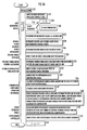
- FIG. 9 is a flowchart (structured flowchart) showing the main routine processing of the control system 50 .
- the components of the control system 50 carrying out pertinent processing are shown on the left end in FIG. 9 .
- control system 50 First, the initialization of the control system 50 is performed in S 10 , then the processing advances to S 14 via S 12 .
- the arithmetic processing of the control system 50 waits for a timer interrupt for each control cycle.
- the control cycle is, for example, 50 ms.
- the processing proceeds to S 16 wherein it determines whether a gait change is observed, and if the determination result is NO, then it proceeds to S 22 , which will be discussed later. If the determination result in S 16 is YES, then the processing proceeds to S 18 wherein it initializes time t to zero, and proceeds to S 20 wherein it sets gait parameters.
- a desired gait of a predetermined period from the moment a predetermined leg (e.g., # 1 ) of the robot 1 leaves a floor to the moment it leaves the floor next (or from the moment it lands to the moment it lands next) is taken as a unit, and gait parameters that are the parameters defining the desired gait for the predetermined period (the parameters used in the algorithm for determining the desired gait) are set in S 20 .
- the “gait change” mentioned in S 16 means the change of the desired gait for the predetermined period. Whether the desired gait has changed may be determined mainly on the basis of time or a detected value of the six-axis force sensor 34 on the predetermined leg.
- the gait parameters set in S 20 are composed of motion parameters that define the desired motion trajectories (specifically, a desired ground contact portion trajectory and a desired body position/posture trajectory) of the robot 1 and the floor reaction force parameters that define desired floor reaction force trajectories (specifically, a desired total floor reaction force trajectory and a desired total floor reaction force central point trajectory).
- the desired total floor reaction force can be obtained by reversing the sign of the resultant force of the inertial force generated by the desired motion and the gravity acting on the robot 1 , so that the floor reaction force parameters may be the ones that define only a desired total floor reaction force central point trajectory.
- motion parameters do not have to include parameters that define a desired body position/posture trajectory if a desired ground contact portion trajectory (more generally, the parameter of a desired motion other than desired body position/posture) and a desired total floor reaction force central point are determined, and then desired body position/posture are determined using a dynamic model of the robot 1 such that the horizontal component of a moment generated about a desired total floor reaction force central point (desired ZMP) by the resultant force of the inertial force generated by a desired motion, including desired body position/posture of the robot 1 , and the gravity acting on the robot 1 becomes zero.
- the processing proceeds to S 22 wherein the instantaneous value of a desired gait is determined on the basis of the aforesaid gait parameters.
- “instantaneous value” means a value for each control cycle
- a desired gait instantaneous value is composed of the instantaneous values of desired body position/posture, a desired ground contact portion position (the instantaneous value of a desired ground contact portion trajectory), a desired total floor reaction force, and a desired total floor reaction force central point position (a desired ZMP position).
- the postures of the ground contact portions 10 cannot be controlled, so that the instantaneous values of the desired postures of the ground contact portions 10 are not determined.
- the parameters defining the desired postures of the ground contact portions may be included in the gait parameters and the instantaneous values of the desired postures of the ground contact portions may be determined on the basis of the parameters.
- the processing of S 14 to S 22 described above is the processing carried out by the gait generating device 100 .
- desired node floor reaction forces including at least the desired floor reaction forces of the ground contact portions 10 (leaf nodes)
- desired node floor reaction forces of leaf nodes are determined.
- This processing of S 26 is also the processing carried out as described above by the desired floor reaction force distributor 102 .
- the compliance mechanisms are provided on other portions in addition to the distal portions of the legs # 1 to # 4 , then the desired floor reaction forces of intermediate nodes that are not leaf nodes should be also determined.
- the moment horizontal component of a desired node floor reaction force is zero.
- the processing proceeds to S 28 wherein the state of the robot 1 , such as the actual body posture inclination, is detected from an output of the posture sensor 36 or the like.
- the value of an actual body posture inclination detected by the posture sensor 36 is captured by the posture error calculator 103 , and a body posture inclination error ⁇ berr is calculated from the detected value and the desired body posture inclination (the instantaneous value at the current time) out of the desired body position/posture.
- a compensating total floor reaction force for stabilizing the posture of the robot 1 is determined from the state of the robot 1 detected in S 28 .
- the horizontal components Mdmdx and Mdmdy of a compensating total floor reaction force moment Mdmd about a desired total floor reaction force central point are calculated by the posture stabilization control calculator 104 from the body posture inclination error ⁇ berr according to the above expression 5 and expression 6.
- the processing proceeds to S 32 wherein the actual floor reaction force of each ground contact portion 10 is detected.
- This is the processing carried out by the actual floor reaction force detector 108 .
- the actual floor reaction force for each ground contact portion 10 detected by the six-axis force sensor 34 that is converted to a supporting leg coordinate system (global coordinate system) is determined.
- the actual floor reaction force of each ground contact portion 10 may be referred to as an actual ground contact portion floor reaction force in some cases.
- the hierarchical compliance operation determiner 114 determines the translational force components and moment components of the desired node floor reaction forces of nodes excluding leaf nodes (more specifically, the translational force components and the moment components that have desired node floor reaction force central points as the points of action) mainly on the basis of the desired node floor reaction forces of the leaf nodes determined by the desired floor reaction force distributor 102 .
- the translational force components of the desired floor reaction forces (desired node floor reaction forces) of the nodes in the state shown in FIG. 3( b ) are illustratively shown in FIG. 10 .
- the hierarchical compliance operation determiner 114 determines the moment component of a desired node floor reaction force of each node, excluding leaf nodes, a desired node floor reaction force central point being the point of action, as in the case of the translational force component of a desired node floor reaction force.
- the moment horizontal component of a desired n-th node floor reaction force is always set to zero.
- the ground contact portions 10 are engaged with the spherical joints 12 (free joints) at the distal portions of the legs # 1 to # 4 , so that floor reaction force moments (horizontal components and vertical components) cannot be generated in the ground contact portions 10 (leaf nodes). For this reason, in the hierarchical compliance operation determiner 114 , the moment vertical components of the desired node floor reaction forces of the ground contact portions 10 (leaf nodes) are also set to zero.
- a desired node floor reaction force moment vertical component of a node that is not a leaf node is determined so as to dynamically balance with a desired motion of the robot 1 , then it could generally take a non-zero value; however, in the present reference example, the control related to the rotation (the rotation in the yaw direction) of the posture of the robot 1 about the vertical axis is not carried out. In the present reference example, therefore, the setting of the vertical component of the moment of a desired node floor reaction force of a node that is not a leaf node will be omitted. For this reason, the moment components of desired node floor reaction forces in the state shown in FIG. 3( b ) will not be shown. If the control related to the rotation of the posture of the robot 1 about the vertical axis is carried out, then the desired floor reaction force moment vertical components of the nodes should be also set.
- the determination need not be performed by the hierarchical compliance operation determiner 114 .
- the hierarchical compliance operation determiner 114 also determines the translational force component and the moment component of an actual node floor reaction force, which is the actual floor reaction force of each node.
- the translational force components of the actual floor reaction forces of the nodes (actual node floor reaction forces) in the state shown in FIG. 3( b ) are illustratively shown in FIG. 11 .
- the translational force component of the actual floor reaction force of each node that is not a leaf node is the resultant force of the translational force components of the actual floor reaction forces of all child nodes of the node.
- the translational force components F 1 act, F 2 act, F 3 act, and F 4 act of the actual floor reaction forces of the leaf nodes are the translational force components of the actual floor reaction forces (actual ground contact portion floor reaction forces) of the ground contact portions 10 obtained by the actual floor reaction force detector 108 .
- the vectors shown by dashed lines in FIG. 11 indicate the translational force components of the desired node floor reaction forces shown in FIG. 10 mentioned above.
- the hierarchical compliance operation determiner 114 determines the translational force components of the actual node floor reaction forces of the nodes from the actual floor reaction forces of the ground contact portions 10 obtained by the actual floor reaction force detector 108 .
- no floor reaction force moment can be generated in the ground contact portions 10 (leaf nodes), as described above, so that the moment components of the actual floor reaction forces of leaf nodes (actual ground contact portion floor reaction forces) will be always zero. Thus, the moment components of the actual node floor reaction forces of the leaf nodes will not be shown.
- the actual floor reaction force moment components of nodes that are not leaf nodes are not generally zero.
- a moment is usually generated about the desired 14th node floor reaction force central point Q 14 by the horizontal components of the translational force components of the actual floor reaction forces of the first ground contact portion 10 (the 1st node) and the fourth ground contact portion 10 (the 4th node).
- the distal portions of the legs are provided with the spherical joints 12 , which are free joints, so that a component in the same direction as a segment Q 1 Q 4 of M 14 act and a component in the same direction as a segment Q 2 Q 3 of M 23 act will be zero.
- an operation for correcting the postures of the ground contact portions should be performed such that the actual floor reaction force moment horizontal component of each ground contact portion approximates a desired floor reaction force moment horizontal component or that the actual floor reaction force moment of each ground contact portion approximates the sum (the vector sum) of the desired floor reaction force moment horizontal component and its ground contact portion compensating floor reaction force moment.
- the processing of the hierarchical compliance operation determiner 114 will be explained in more detail.
- a situation is assumed in which the posture of the body 24 of the robot 1 is about to fall toward left rear in the state shown in FIG. 3( b ) and the compensating total floor reaction force moment Mdmd determined by the posture stabilization control calculator 104 is as shown in FIG. 13 .
- the horizontal component of the desired total floor reaction force moment Mtotalref is zero.
- the horizontal component of the actual total floor reaction force moment about the desired total floor reaction force central point may be made to follow the horizontal components (Mdmdx, Mdmdy) of Mdmd.
- the actual floor reaction force moment about the desired floor reaction force central point of each ground contact portion 10 is zero.
- the hierarchical compliance operation determiner 114 in the first reference example corrects the desired ground contact portion position (especially the position in the height direction) of each ground contact portion 10 determined by the gait generating device 100 so as to satisfy the aforesaid requirements 1) and 2) as much as possible.
- the hierarchical compliance operation determiner 114 determines a compensating angle.
- the compensating angle is a manipulated variable (a rotational amount) for correcting the relative relationship among the positions of the ground contact portions 10 by the operation of rotation about a certain point (correcting in the vertical direction in the present reference example).
- they are the compensating angles of the nodes other than leaf nodes.
- the 14th node compensating angle ⁇ 14 is the angle formed by a segment Q 1 Q 4 and a segment Q 1 ′Q 4 ′
- the 23rd node compensating angle ⁇ 23 is the angle formed by a segment Q 2 Q 3 and a segment Q 2 ′Q 3 ′
- the 1423rd node compensating angle ⁇ 1423 is the angle formed by a segment Q 14 Q 23 and a segment Q 14 ′Q 23 ′.
- a normal vector V 14 of a plane that includes a desired first node floor reaction force central point Q 1 (the desired floor reaction force central point of a first ground contact portion 10 ) and a desired fourth node floor reaction force central point Q 4 (the desired floor reaction force central point of a second ground contact portion 10 ) and that is perpendicular to a horizontal plane is determined.
- the magnitude of V 14 is 1.
- the coordinate (position) of the desired first node floor reaction force central point Q 1 is rotationally moved about a normal vector V 14 with the desired 14th node floor reaction force central point Q 14 being the center of rotation (about the axis that passes Q 14 and is parallel to V 14 ) by the aforesaid 14th node compensating angle ⁇ 14 .
- the point after Q 1 is moved by the above rotational movement is defined as Q 1 ′.
- the coordinate (position) of the desired fourth node floor reaction force central point Q 4 is rotationally moved about the normal vector V 14 with the desired 14th node floor reaction force central point being the center of rotation by the 14th node compensating angle ⁇ 14 .
- the point after Q 4 is moved by the above rotational movement is defined as Q 4 ′.
- the end points of a segment obtained by rotating the segment Q 1 Q 4 about V 14 by ⁇ 14 with Q 14 which is an internally dividing point thereof, being the center of rotation are defined as Q 1 ′ and Q 4 ′.
- the 14th node compensating angle ⁇ 14 is a manipulated variable for moving the relative relationship of the positions of the desired floor reaction force central points Q 1 and Q 4 of the first node and the fourth node, respectively, which are child nodes of the 14th node, without moving the position of the desired floor reaction force central point Q 14 of the 14th node.
- a normal vector V 23 of a plane that includes a desired second node floor reaction force central point Q 2 and a desired third node floor reaction force central point Q 3 and that is perpendicular to a horizontal plane is determined.
- the magnitude of V 23 is 1.
- the coordinate (position) of the desired second node floor reaction force central point Q 2 is rotationally moved about the normal vector V 23 with the desired 23rd node floor reaction force central point Q 23 being the center of rotation (about the axis that passes Q 23 and is parallel to V 23 ) by the 23rd node compensating angle ⁇ 23 .
- the point after Q 2 is moved by the above rotational movement is defined as Q 2 ′.
- the coordinate (position) of the desired third ground contact portion floor reaction force central point Q 3 is rotationally moved about the normal vector V 23 with the desired 23rd node floor reaction force central point being the center of rotation by the 23rd node compensating angle ⁇ 23 .
- the point after Q 3 is moved by the above rotational movement is defined as Q 3 ′.
- the end points of a segment obtained by rotating the segment Q 2 Q 3 about V 23 by ⁇ 23 with Q 23 which is an internally dividing point thereof, being the center of rotation are defined as Q 2 ′ and Q 3 ′.
- the 23rd node compensating angle ⁇ 23 is a manipulated variable for moving the relative relationship of the positions of the desired floor reaction force central points Q 2 and Q 3 of the second node and the third node, respectively, which are child nodes of the 23rd node, without moving the position of the desired floor reaction force central point Q 23 of the 23rd node.
- a normal vector V 1423 of a plane that includes a desired 14th node floor reaction force central point Q 14 and a desired 23rd node floor reaction force central point Q 23 and that is perpendicular to a horizontal plane is determined.
- the magnitude of V 1423 is 1.
- the point after Q 14 is moved by the above rotational movement is defined as Q 14 ′.
- the coordinate (position) of the desired 23rd ground contact portion floor reaction force central point Q 23 is rotationally moved about the normal vector V 1423 with the desired total floor reaction force central point P being the center of rotation by the 1423rd compensating angle ⁇ 1423 .
- the point after Q 23 is moved by the above rotational movement is defined as Q 23 ′.
- the 1423rd node compensating angle ⁇ 1423 is a manipulated variable for moving the relative relationship of the positions of the desired floor reaction force central points Q 14 and Q 23 of the 14th node and the 23rd node, respectively, which are child nodes of the 1423rd node, without moving the position of the desired floor reaction force central point P of the 1423rd node.
- a vector whose start point is A and end point is B will be denoted as a vector A_B.
- a point Q 1 ′′ that would be obtained when Q 1 ′ is moved for a vector Q 14 _Q 14 ′ is determined.
- a point Q 4 ′′ that would be obtained when Q 4 ′ is moved for a vector Q 14 _Q 14 ′ is determined.
- a point Q 2 ′′ that would be obtained when Q 2 ′ is moved for a vector Q 23 _Q 23 ′ is determined.
- a point Q 3 ′′ that would be obtained when Q 3 ′ is moved for a vector Q 23 _Q 23 ′ is determined.
- the processing for moving the desired floor reaction force central points of the child nodes of the 14th node, the 23rd node, and the 1423rd node, respectively, on the basis of the compensating angles ⁇ 14 , ⁇ 23 , and ⁇ 1423 , as described above, is equivalent to moving the positions of the child nodes of the 14th node, the 23rd node, and the 1423rd node, respectively, on the basis of the compensating angles ⁇ 14 , ⁇ 23 , and ⁇ 1423 .
- the aforesaid parallel movement is performed without changing the postures (desired postures) of ground contact portions, and then the n-th ground contact portion is further rotated by a certain rotational angle ⁇ n_x about a longitudinal axis (X axis) and also rotated about a lateral axis (Y axis) by a certain rotational angle ⁇ n_y, with Qn′′ being the center. This corrects the desired postures of ground contact portions.
- the rotational angle ⁇ n (a two-dimensional amount composed of ⁇ n_x and ⁇ n_y) in this case is referred to as an n-th ground contact portion compensating angle
- ⁇ n_x is referred to as an n-th ground contact portion compensating angle X component
- ⁇ n_y is referred to as an n-th ground contact portion compensating angle Y component.
- the n-th ground contact portion compensating angle ⁇ n may be determined according to the technique described in Japanese Unexamined Patent Application Publication No. H10-277969 previously proposed by the present applicant.
- each of the node compensating angles is determined such that a resultant force of a desired floor reaction force moment (the horizontal component thereof is zero) and a node compensating floor reaction force moment Mn_dmd is generated there.
- the compensating total floor reaction force moment Mdmd which provides the basis of the node compensating floor reaction force moment Mn_dmd, is determined such that an actual posture inclination error approximates zero.
- each node compensating angle will function as a manipulated variable for manipulating the relative positional relationship among the ground contact portions 10 such that an actual posture inclination error approximates zero while bringing a floor reaction force moment about a desired total floor reaction force central point close to a desired moment (a compensating total floor reaction force moment in this case).
- the processing for correcting the desired ground contact portion positions (specifically, the mutual relative relationship among the positions) of the ground contact portions 10 is the hierarchical compliance operation in the first reference example.
- the manipulated variable (correction amount) of the relative relationship among the desired ground contact portion positions (relative positional relationship) of the ground contact portions 10 which are the descendant nodes of the node, is determined for each of the compensating angles ⁇ 14 , ⁇ 23 , and ⁇ 1423 , and the manipulated variables (correction amounts) are combined so as to correct the mutual relative relationship of the desired ground contact portion positions of the ground contact portions 10 .
- the desired ground contact portion position/posture corrected as described above are referred to as corrected desired ground contact portion position/posture.
- a ground contact region (a region of the ground contact surface wherein the pressure is positive) remains unchanged even if the ground contact pressure distribution of each ground contact portion 10 changes.
- the compliance mechanism 42 attached to each ground contact portion 10 deforms in proportion to a compensating angle, and an actual floor reaction force of each ground contact portion 10 based on the amount of the deformation is generated.
- the relationship between the compensating angles and the changing amounts of the actual floor reaction forces generated by the compensating angles has good characteristics, namely, linear characteristics, shown below.
- FIG. 17 is a block diagram showing the functions of the hierarchical compliance operation determiner 114 in the present reference example. Referring to the diagram, the processing of the hierarchical compliance operation determiner 114 will be explained in further detail.
- the hierarchical compliance operation determiner 114 is equipped with, as its functional means, a compensating total floor reaction force moment distributor 114 a , compensating angle determiners 114 b , 114 c and 114 d , a corrected desired ground contact portion position/posture calculator 114 g , a deformation compensation amount calculator 114 n , and a corrected desired ground contact portion position/posture with deformation compensation calculator 114 h.
- the compensating total floor reaction force moment distributor 114 a distributes the aforesaid compensating total floor reaction force moment Mdmd (Mdmdx, Mdmdy) to the 1423rd node compensating floor reaction force moment M 1423 dmd, the 14th node compensating floor reaction force moment M 14 dmd and the 23rd node compensating floor reaction force moment M 23 dmd.
- the component of the 1423rd node compensating floor reaction force moment M 1423 dmd in the direction of the aforesaid vector V 1423 (the component about the axis in the V 1423 direction) is described as M 1423 dmdv.
- the vector V 1423 is the vector defined in the general explanation of the compliance operation of the hierarchical compliance operation determiner 114 (refer to FIG. 16 ).
- the 14th node compensating floor reaction force moment M 14 dmd is the desired value of a moment to be generated about the desired 14th node floor reaction force central point by the translational force components of the floor reaction forces of the ground contact portions 10 (specifically, the first and the fourth ground contact portions) when the 14th compensating angle ⁇ 14 is manipulated.
- the component of the 14th node compensating floor reaction force moment M 14 dmd in the direction of the vector V 14 is described as M 14 dmdv.
- the vector V 14 is the vector defined in the general explanation of the compliance operation of the hierarchical compliance operation determiner 114 (refer to FIG. 15 ). If a vector orthogonal to V 14 and also orthogonal to the vertical direction is defined as U 14 , then the component M 14 dmdu in the direction of U 14 of the 14th node compensating floor reaction force moment M 14 dmd is set to zero in the present reference example. This is because the component of a floor reaction force moment in the U 14 direction cannot be generated even if the 14th node compensating angle ⁇ 14 is manipulated in the robot 1 of the present reference example. In the present reference example, the component of M 14 dmd in the vertical direction is also set to zero.
- the 23rd node compensating floor reaction force moment M 23 dmd is the desired value of a moment to be generated about the desired 23rd node floor reaction force central point by the translational force components of the floor reaction forces of the ground contact portions 10 (specifically, the second and the third ground contact portions) when the 23rd compensating angle ⁇ 23 is manipulated.
- the component of the 23rd node compensating floor reaction force moment M 23 dmd in the direction of the vector V 23 is described as M 23 dmdv.
- the vector V 23 is the vector defined in the general explanation of the compliance operation of the hierarchical compliance operation determiner 114 (refer to FIG. 15 ). If a vector orthogonal to V 23 and also orthogonal to the vertical direction is defined as U 23 , then the component M 23 dmdu in the direction of U 23 of the 23rd node compensating floor reaction force moment M 23 dmd is set to zero in the present reference example.
- the component of M 23 dmd in the vertical direction is also set to zero.
- the 1423rd node compensating floor reaction force moment M 1423 dmd, the 14th node compensating floor reaction force moment M 14 dmd, and the 23rd node compensating floor reaction force moment M 23 dmd are determined, for example, as follows.
- a desired n-th node floor reaction force central point has been corrected while maintaining the horizontal component of an n-th node compensating floor reaction force moment at zero so as to be equivalent to adding the n-th node compensating floor reaction force moment to the desired n-th node floor reaction force central point
- the desired n-th node floor reaction force central point position that has been corrected is referred to as a corrected desired n-th node floor reaction force central point position.
- the desired 1423rd node floor reaction force central point Q 1423 agrees with the total floor reaction force central point P, so that the corrected desired 1423rd node floor reaction force central point Pmdfd may be referred to as a corrected desired total floor reaction force central point in some cases.
- M 1423 dmd ( Pmdfd ⁇ P )* F totalref Expression 7
- M 14 dmd ( Q 14 mdfd ⁇ Q 14)* F 14ref Expression 8
- M 23 dmd ( Q 23 mdfd ⁇ Q 23)* F 23ref Expression 9
- the difference between two points means the difference in the positional vectors of the points.
- Ftotalref, F 14 ref, and F 23 ref denote the translational force components of the desired node floor reaction forces of the 1423rd node, the 14th node, and the 23rd node, respectively, as shown in FIG. 10 .
- control should not be carried out to bring the floor reaction force of the ground contact portion 10 to be in contact with the ground excessively close to zero or a negative value.
- the following conditions 1) to 3) should be satisfied.
- Pmdfd is not excessively close to an end point of the segment Q 14 Q 23 from the total floor reaction force central point P and exists on the segment Q 14 Q 23 .
- the range in which the corrected desired 1423rd node floor reaction force central point (corrected desired total floor reaction force central point) Pmdfd should exist is referred to as the existence permissible range of the corrected desired 1423rd node floor reaction force central point (corrected desired total floor reaction force central point).
- Q 14 mdfd is not excessively close to an end point of the segment Q 1 Q 4 from the desired 14th node floor reaction force central point Q 14 and exists on the segment Q 1 Q 4 .
- the range in which the corrected desired 14th node floor reaction force central point Q 14 mdfd should exist is referred to as the existence permissible range of the corrected desired 14th node floor reaction force central point.
- Q 23 mdfd is not excessively close to an end point of the segment Q 2 Q 3 from the desired 23rd node floor reaction force central point Q 23 and exists on the segment Q 2 Q 3 .
- the range in which the corrected desired 23rd node floor reaction force central point Q 23 mdfd should exist is referred to as the existence permissible range of the corrected desired 23rd node floor reaction force central point.
- the resultant force of the 1423rd node compensating floor reaction force moment M 1423 dmd, the 14th node compensating floor reaction force moment M 14 dmd, and the 23rd node compensating floor reaction force moment M 23 dmd should approximately agree with the compensating total floor reaction force moment Mdmd.
- the following expression 10 should be approximately satisfied.
- Mdmd M 1423 dmd+M 14 dmd+M 23 dmd Expression 10
- the 1423rd node compensating floor reaction force moment M 1423 dmd, the 14th node compensating floor reaction force moment M 14 dmd, and the 23rd node compensating floor reaction force moment M 23 dmd are determined according to expressions 11 to 13 given below as long as the positions of the corrected desired node floor reaction force central points Pmdfd, Q 14 mdfd and Q 23 mdfd determined by the above moments and the aforesaid expression 7, expression 8, and expression 9 satisfy the aforesaid corrected node existence position conditions 1), 2) and 3).
- M 1423 dmd Mat 1423 *Mdmd*V 1423 Expression 11
- M 14 dmd Mat 14 *Mdmd*V 14 Expression 12
- M 23 dmd Mat 23 *Mdmd*V 23 Expression 13
- Mat 1423 , Mat 14 , and Mat 23 denote gain matrixes (1-row, 3-column matrixes whose third elements are zero), and these are set such that M 1423 dmd, M 14 dmd, and M 23 dmd determined according to expression 11, expression 12, and expression 13 satisfy expression 10.
- the gain matrixes Mat 1423 , Mat 14 , and Mat 23 are determined such that a simultaneous equation composed of expression 10, expression 11, expression 12, and expression 13 identically holds regardless of the value of Mdmd.
- the gain matrix for the simultaneous equation to identically hold is not uniquely determined, so that an appropriate gain matrix may be determined depending on, for example, which one of the corrected node existence position conditions 1), 2) and 3) is especially important.
- the gain matrixes are desirably changed continuously so as to make the compensating angles ⁇ 1423 , ⁇ 14 and ⁇ 23 continuously change. Further, the policy of setting gain matrixes may be changed according to whether the robot 1 is standing upright or the difference in movement mode or the like.
- the 1423rd node compensating floor reaction force moment M 1423 dmd, the 14th node compensating floor reaction force moment M 14 dmd, and the 23rd node compensating floor reaction force moment M 23 dmd determined according to expression 11, expression 12, and expression 13 do not satisfy any one of the corrected node existence position conditions 1), 2) and 3), then they are corrected to satisfy the conditions 1), 2) and 3).
- a corrected desired node floor reaction force central point that has exceeded the existence permissible range is set at a point on the boundary of the existence permissible range, and the remaining corrected desired node floor reaction force central points are determined so that they satisfy expression 11, expression 12, and expression 13 as much as possible (to minimize the absolute value of the difference between a left side and a right side as much as possible).
- expression 11, expression 12, and expression 13 are determined so that they satisfy expression 11, expression 12, and expression 13.
- the compensating total floor reaction force moment distributor 114 a determines the node compensating floor reaction force moments M 1423 dmd, M 14 dmd, and M 23 dmd as described above.
- FIG. 14 shows the examples of the node compensating floor reaction force moments M 1423 dmd, M 14 dmd, and M 23 dmd determined as described above.
- Mdmd is the same as that shown in FIG. 13 mentioned above.
- generating a node compensating floor reaction force moment at a desired n-th node floor reaction force central point of an n-th node having child nodes is equivalent to correcting the weights of the child nodes of the n-th node.
- the processing of the compensating angle determiner ( ⁇ 1423 determiner) 114 b out of the aforesaid compensating angle determiners 114 b to 114 d will be explained with reference to the block diagram of FIG. 19 . If the translational force component (F 1 act+F 4 act) of the resultant force of the actual first node floor reaction force and the actual fourth node floor reaction force acts on a desired 14th node floor reaction force central point Q 14 and the translational force component (F 2 act+F 3 act) of the resultant force of the actual second node floor reaction force and the actual third node floor reaction force acts on a desired 23rd node floor reaction force central point Q 23 , then a moment M 1423 act generated about the desired total floor reaction force central point P (the desired 1423rd node floor reaction force central point) by the above translational force components is determined according to expression 14 given below.
- M 1423act P — Q 14*( F 1act+ F 4act)+ P — Q 23*( F 2act+ F 3act) Expression 14 where P_Q 14 denotes a vector whose start point is P and end point is Q 14 , and P_Q 23 denotes a vector whose start point is P and end point is Q 23 .
- Fn_act the translational force components
- the actual floor reaction force moment acting about the desired 14th node floor reaction force central point Q 14 and the actual floor reaction force moment acting about the desired 23rd node floor reaction force central point Q 23 are subtracted from the actual total floor reaction force moment Mtotalact acting about the desired total floor reaction force central point P.
- an actual n-th node floor reaction force moment Mn_act of an arbitrary n-th node is the actual floor reaction force moment of an n-th ground contact portion.
- an arbitrary n-th node which is not a leaf node
- the moment from the floor reaction forces of all child nodes thereof acting on the desired n-th node floor reaction force central point is referred to as an actual n-th node floor reaction force moment Mn_act.
- an actual n-th node floor reaction force moment has a definition that includes the actual floor reaction force moments of child nodes and a definition that does not include them; however, either of the definitions may be used.
- the horizontal components of the actual floor reaction force moments of child nodes immediately converge to zero, so that the behavior of the control of the actual floor reaction force of an n-th node does not change much when either of the definitions is used.
- Expression 16 shown below is a general expression for calculating an actual n-th node floor reaction force moment corresponding to expression 14, and expression 17 is a general expression for calculating an actual n-th node floor reaction force moment corresponding to expression 15.
- Qn_Qm is a vector whose start point is Qn and end point is Qm.
- An actual floor reaction force moment Mm_act of an m-th node, which is a leaf node, is an actual floor reaction force moment of each ground contact portion detected by an actual floor reaction force detector.
- ⁇ in expressions 16 and 17 means the total sum regarding m.
- the actual floor reaction force moment about the desired floor reaction force central point of a leaf node (each ground contact portion) becomes zero; therefore, the right side of the above expression 15 does not include a component of Mm_act of expression 17.
- Mm_act of expression 17 In a robot in which the postures of ground contact portions can be controlled, Mm_act of expression 17 generally does not become zero.
- the 1423rd node compensating angle ⁇ 1423 may generally be determined by feedback control law or the like such that the difference between M 1423 act determined as described above and the 1423rd node compensating floor reaction force moment M 1423 dmd previously determined by the compensating total floor reaction force moment distributor 114 a (M 1423 act ⁇ M 1423 dmd) approximates zero.
- ⁇ 1423 may be determined by, for example, multiplying the difference by a predetermined gain matrix (tertiary diagonal matrix).
- the 1423rd node compensating angle ⁇ 1423 about the axis in the direction of the aforesaid vector V 1423 may be determined, so that ⁇ 1423 may be determined on the basis of the difference between a component M 1423 actv in the direction of the vector V 1423 of M 1423 act and a component M 1423 dmdv in the direction of the vector V 1423 of M 1423 dmd.
- M 1423 actv and M 1423 dmdv are passed through a filter before determining ⁇ 1423 on the basis of the difference therebetween in order to enhance the responsiveness and stability of the control of floor reaction forces.
- the component M 1423 actv of M 1423 act in the direction of the vector V 1423 determined as described above is extracted. This is obtained by the following expression 18 using a scalar product calculation “ ⁇ ” of a vector.
- M 1423act v M 1423act ⁇ V 1423 Expression 18
- the processing for calculating M 1423 actv as described above is executed by a calculator indicated by a reference numeral 114 k in FIG. 19 .
- M 1423 actv is passed through a low-pass filter 114 i to obtain M 1423 actvfilt. Furthermore, the component M 1423 dmdv of the aforesaid 1423rd node compensating floor reaction force moment M 1423 dmd in the V 1423 direction is passed through a compensating filter 114 j to obtain M 1423 dmdvfilt.
- M 1423 dmdv is determined by the scalar product calculation of M 1423 dmd and V 1423 , as with the aforesaid expression 18. Then, the result obtained by subtracting M 1423 dmdvfilt from M 1423 actvfilt provides a component M 1423 errv in the direction of an error moment V 1423 .
- the aforesaid compensating filter 114 j improves the frequency response characteristic of transfer functions from M 1423 dmdv to an actual total floor reaction force moment in a control system.
- the aforesaid 1423rd node compensating angle ⁇ 1423 is obtained by the calculation of the feedback control law (proportional control law in this case) of the following expression 19.
- K 1423 denotes a control gain, and it is normally set to a positive value.
- ⁇ 1423 K 1423 *M 1423err v Expression 19 This means that the component M 1423 errv in the direction of the error moment V 1423 is multiplied by the control gain K 1423 to obtain the 1423rd node compensating angle ⁇ 1423 .
- the processing of the compensating angle determiner ( ⁇ 14 determiner) 114 c in FIG. 17 will now be explained with reference to FIG. 20 . If the translational force component F 1 act of the actual first node floor reaction force (the actual floor reaction force of the first ground contact portion 10 ) acts on a desired first node floor reaction force central point Q 1 and the translational force component F 4 act of the actual fourth node floor reaction force (the actual floor reaction force of the fourth ground contact portion 10 ) acts on a desired fourth node floor reaction force central point Q 4 , then a moment M 14 act generated about the desired 14th node floor reaction force central point Q 14 by the above translational force components is determined according to the aforesaid expression 16, which is a general expression.
- M 14act Q 14 — Q 1 *F 1act+ Q 14 — Q 4 *F 4act Expression 20 where Q 14 _Q 1 denotes a vector whose start point is Q 14 and end point is Q 1 , and Q 14 _Q 4 denotes a vector whose start point is Q 14 and end point is Q 4 .
- Expression 21 is an expression for calculating the moment acting about the desired 14th node floor reaction force central point generated by the resultant force of the actual floor reaction forces of all leaf nodes of the 14th node.
- expression 20 subtracts the actual first node floor reaction force moment and the actual fourth node floor reaction force moment from the moment acting about the desired 14th floor reaction force central point generated by the resultant force of the actual floor reaction forces of all leaf nodes of the 14th node.
- the 14th node compensating angle ⁇ 14 may be generally determined by the feedback control law or the like such that the difference between M 14 act determined as described above and the 14th node compensating floor reaction force moment M 1423 dmd previously determined by the compensating total floor reaction force moment distributor 114 a (M 14 act ⁇ M 14 dmd) approximates zero.
- ⁇ 14 is determined on the basis of the difference between the component M 14 actv of M 14 act in the aforesaid direction of the vector V 14 and the component M 14 dmdv of M 14 dmd in the direction of the vector V 14 , which have been respectively passed through a filter.
- the processing for calculating M 14 actv as described above is carried out by a calculator indicated by a reference character 114 k ′ in FIG. 20 .
- the aforesaid M 14 actv is passed through a low-pass filter 114 i ′ to obtain M 14 actvfilt.
- the component M 14 dmdv of the aforesaid 14th node compensating floor reaction force moment M 14 dmd in the direction of V 14 is passed through a compensating filter 114 j ′ to obtain M 14 dmdvfilt.
- M 14 dmdv is determined by the scalar product calculation of M 14 dmd and V 14 .
- M 14 dmdvfilt is subtracted from M 14 actvfilt to obtain a component M 14 errv in the direction of an error moment V 14 .
- the compensating filter 114 j ′ improves the frequency response characteristics of transfer functions from M 14 dmdv to actual total floor reaction force moments in a control system.
- the processing of the compensating angle determiner ( ⁇ 23 determiner) 114 d in FIG. 17 is the same as the processing of the 14th node compensating angle ⁇ 14 determiner 114 c ; therefore, detailed explanation thereof will be omitted here.
- the following provides an overview of the processing.
- a component M 23 actv of a moment M 23 act in the direction of a vector V 23 the moment being generated about a desired 23rd node floor reaction force central point Q 23 by the actual floor reaction forces of the child nodes of a 23rd node, is calculated on the basis of the aforesaid expression 16 or 17.
- the 23rd node compensating angle ⁇ 23 is calculated by the arithmetic processing of the feedback control law (proportional control law) from a component M 23 errv in the direction of the error moment V 23 obtained by subtracting M 23 actvfilt, which is obtained by passing the above M 23 actv through a low-pass filter, from M 23 dmdvfilt obtained by passing the component M 23 dmdv of the aforesaid 23rd node compensating floor reaction force moment M 23 dmd in the direction of V 23 through a compensating filter.
- the feedback control law proportional control law
- the processing of the compensating angle determiners 114 b to 114 d determines the sets of the node compensating angles ⁇ 1423 , ⁇ 14 , and ⁇ 23 such that the horizontal components of the actual moments Mact acting on the desired total floor reaction force central points P approximate the compensating total floor reaction force moment Mdmd.
- ⁇ 1423 has been determined by the aforesaid expression 19; alternatively, however, it may be determined on the basis of the difference between M 1423 act+M 14 act+M 23 act (the total sum of actual node floor reaction force moments) and M 1423 dmd or the difference between the total sum of actual node floor reaction force moments and M 1423 dmd, which have been respectively passed through a filter, in place of M 1423 err of the right side of expression 19.
- a node compensating floor reaction force moment has been determined without changing the desired node floor reaction force central point Qn of each node, the Qn being the point of action. Then, the difference between the node floor reaction force compensating moment (more precisely, the resultant force of the node compensating floor reaction force moment and the moment component of the desired node floor reaction force having Qn as its point of action) and an actual node floor reaction force moment having Qn as its point of action has been used as a control amount to determine a node compensating angle such that the control amount approximates zero.
- the node compensating angles ⁇ 1423 , ⁇ 14 and ⁇ 23 may be determined as follows.
- the actual 14th node floor reaction force central point related to the 14th node is determined as a point obtained by shifting, on the segment Q 1 Q 4 , the desired 14th node floor reaction force central point by the value obtained by dividing the horizontal component of M 14 act determined by the aforesaid expression 16 or 17 by the vertical component of the resultant force of F 1 act and F 4 act (the translational force component of an actual 14th node floor reaction force).
- the node floor reaction force central points of the 23rd node and the 1423rd node is determined as a point obtained by shifting, on the segment Q 1 Q 4 , the desired 14th node floor reaction force central point by the value obtained by dividing the horizontal component of M 14 act determined by the aforesaid expression 16 or 17 by the vertical component of the resultant force of F 1 act and F 4 act (the translational force component of an actual 14th node floor reaction force).
- the corrected desired ground contact portion position/posture calculator 114 g in FIG. 17 obtains corrected desired ground contact portion position/posture by correcting the desired ground contact portion position/posture, which are the desired position and the desired posture of each ground contact portion 10 , according to a technique for correcting the desired ground contact portion position/posture of the aforesaid hierarchical compliance operation (the technique explained with reference to FIG. 15 and FIG. 16 ) on the basis of the 1423rd node compensating angle ⁇ 1423 , the 14th node compensating angle ⁇ 14 , and the 23rd node compensating angle ⁇ 23 .
- the distal portions of the legs # 1 to # 4 have free joints (spherical joints 12 ), and the posture of each ground contact portion 10 cannot be intentionally changed, so that the corrected desired ground contact portion position/posture actually mean the corrected desired ground contact portion position.
- FIG. 21 is a functional block diagram showing the processing of the aforesaid deformation compensation amount calculator 114 n in FIG. 17 .
- the corrected desired ground contact portion position/posture with deformation compensation calculator 114 h in FIG. 17 adds a further correction to the corrected desired ground contact portion position/posture of each ground contact portion 10 (the position/posture determined by the aforesaid corrected desired ground contact portion position/posture calculator 114 g ) so as to cancel the calculated deformation amount En_mdfd, thereby obtaining the corrected desired ground contact portion position/posture with deformation compensation of each ground contact portion 10 .
- the corrected desired ground contact portion positions/postures with deformation compensation are determined by adding individually corresponding deformation compensation amounts En_cmpn to the corrected desired ground contact portion position/posture of the ground contact portions 10 .
- the corrected desired ground contact portion floor reaction force is corrected so as to lower the desired position of the ground contact portion 10 by z.
- the corrected desired ground contact portion position/posture with deformation compensation is calculated such that the position/posture when the ground contact surface (bottom surface) of the ground contact portion 10 after deformation compensation is deformed under a desired ground contact portion floor reaction force agrees with the desired position/posture of the ground contact surface of the ground contact portion before the deformation compensation.
- the postures of the ground contact portions 10 cannot be controlled, so that the corrected desired ground contact portion position/posture with deformation compensation calculator 114 h actually corrects the corrected desired ground contact portion positions of the ground contact portions 10 .
- the deformation compensation described above is implemented by control for canceling in a feed-forward manner the shifts in actual ground contact portion position/posture caused by a deformation of the compliance mechanism 42 or the like. In comparison with a case where no such control is carried out, it is possible to enable the robot 1 to travel in a mode that is further closer to a desired gait.
- FIG. 22 is a flowchart showing a generalized subroutine of the processing for determining the compensating angles.
- This processing is carried out as described above by the aforesaid compensating total floor reaction force moment distributor 114 a.
- the processing proceeds to S 106 to determine the vectors V 1423 , V 14 and V 23 , which have been defined in the explanation of the hierarchical compliance operation, and vectors U 1423 , U 14 and U 23 orthogonal thereto.
- the floor reaction force moments in the directions of the vectors U 1423 , U 14 and U 23 cannot be generated; therefore, it is unnecessary to determine U 1423 , U 14 and U 23 .
- Vn may be taken in any direction as long as it does not suddenly change timewise; hence, the direction of Vn may be appropriately determined by, for example, setting it to the direction of the X axis of a supporting leg coordinate system or the direction of the body of a robot. Further, Un is to be orthogonal to Vn.
- This may be accomplished by carrying out the scalar product calculation of Mn_act and Vn and Un.
- the component Mn_actu in the Un direction is zero. Hence, it is unnecessary to determine Mn_actu.
- This may be accomplished by carrying out the scalar product calculation of Mn_dmd and Vn and Un.
- the component Mn_dmdu in the Un direction of the n-th node compensating floor reaction force moment Mn_dmd is set to zero. Alternatively, it is unnecessary to determine Mn_dmdu.
- the processing proceeds to S 112 to determine a Vn component of an n-th node compensating angle ⁇ n by multiplying the difference between a value obtained by passing Mn_actv through a filter and a value obtained by passing Mn_dmdv through a filter by a gain Kn (more generally, according to the feedback control law from the difference).
- this processing is carried out as described above on the 14th node, the 23rd node and the 1423rd node by the aforesaid compensating angle determiners 114 b , 114 c and 114 d.
- the processing of S 106 to S 114 may be regarded as the processing for determining an n-th node compensating angle such that the actual n-th node floor reaction force moment acting on a desired n-th node floor reaction force central point converges to an n-th node compensating floor reaction force moment (more precisely, the resultant force of the n-th node compensating floor reaction force moment and the desired node floor reaction force moment acting on the desired n-th node floor reaction force central point).
- the processing proceeds to S 38 to correct desired ground contact portion position/posture on the basis of the compensating angle determined in S 34 and to further correct it on the basis of the deformation compensation amount determined in S 36 , thereby obtaining the corrected desired ground contact portion position/posture with deformation compensation of each ground contact portion 10 .
- the corrected desired ground contact portion positions of the ground contact portions 10 are determined on the basis of the compensating angles ⁇ 1423 , ⁇ 14 and ⁇ 23 as described above (as explained with reference to the aforesaid FIG. 15 and FIG. 16 ) by the corrected desired ground contact portion position/posture calculator 114 g .
- the processing from S 32 to S 38 in FIG. 9 explained above is the processing of the hierarchical compliance operation determiner 114 .
- the processing proceeds to S 40 to calculate the joint displacement command of the robot 1 from the desired body position/posture and the corrected ground contact portion position/posture with deformation compensation (the corrected ground contact portion position with a deformation compensation in the first reference example).
- This processing is carried out as described above by the aforesaid robot geometric model 110 .
- control for stabilizing the posture of a mobile robot can be easily accomplished and the landing shocks to the mobile robot can be reduced, thus allowing the ground contact properties of the mobile robot to be enhanced and also preventing the mobile robot from slipping or spinning when it travels. Furthermore, the load on the actuators of the mobile robot can be reduced. Hence, the floor reaction forces of ground contact portions can be properly controlled, so that high posture stability can be obtained.
- the desired ground contact portion positions have been amended (corrected) so as to rotationally move about node floor reaction force central points without changing the postures of the ground contact portions (without controlling the postures), thereby correcting the relative heights among the ground contact portions 10 from the relative heights among the desired ground contact portion positions.
- only the heights of the ground contact portions 10 may be corrected by moving the desired ground contact portion positions only in the vertical direction.
- a desired ground contact portion position is corrected according to the following procedure.
- a vertical position correction amount Z 14 of a desired 14th node floor reaction force central point and a vertical position correction amount Z 23 of a desired 23rd node floor reaction force central point are determined.
- Z 14 ⁇ PQ 14* ⁇ 1423
- Z 23 PQ 23* ⁇ 1423
- the value determined by the aforesaid expression 19 is substituted into ⁇ 1423 .
- Z 1 ⁇ Q 14 Q 1* ⁇ 14 +Z 14 Expression 28
- Z 4 Q 14 Q 4* ⁇ 14 +Z 14 Expression 29
- Z 2 ⁇ Q 23 Q 2* ⁇ 23 +Z 23 Expression 30
- Z 3 Q 23 Q 3* ⁇ 23 +Z 23 Expression 31
- the value determined by the aforesaid expression 23 is substituted into ⁇ 14 , and the value determined in the same manner as that for ⁇ 14 is substituted into ⁇ 23 .
- the corrected desired ground contact portion positions are obtained by adding Z 1 , Z 2 , Z 3 and Z 4 determined as described above to the desired ground contact portion positions in the vertical direction.
- the ground contact portions 10 have been hierarchized as shown in the aforesaid FIG. 6 ; however, the hierarchical structure does not necessarily have to be decided in advance to be one hierarchical structure.
- the hierarchical structure may be changed according to the travel mode (the motion mode of legs when traveling) of the robot 1 , such as trotting or galloping.
- the ground contact portions 10 may be hierarchized as shown in FIG. 23 .
- FIG. 23 illustrates, as in the aforesaid FIG.
- the pair of the first ground contact portion 10 and the second ground contact portion 10 is defined as a 12th node and the pair of the third ground contact portion 10 and the fourth ground contact portion 10 is defined as a 34th node in a period during which all legs # 1 to # 4 of the robot 1 are all supporting legs.
- FIG. 1 the explanation will be focused on the aspects of a robot 1 of the second reference example that are different from the robot of the first reference example.
- the robot 1 of the second reference example is provided with, in addition to the first to the fourth legs # 1 to # 4 , a fifth leg # 5 and a sixth leg # 6 having the same structures as those of the legs # 1 to # 4 .
- This means that the robot 1 of the second reference example is a six-legged robot.
- the fifth leg # 5 is behind the third leg # 3 and extended from the right side of the body 24 of the robot 1
- the sixth leg # 6 is behind the fourth leg # 4 and extended from the left side of the body 24 of the robot 1 .
- the rest of the mechanical structure of the robot 1 is the same as that of the first reference example, so that the like reference numerals as those of the first reference example will be assigned and the explanation thereof will be omitted.
- the basic concept of the technique of the hierarchical compliance control of the robot 1 (six-legged robot) of the second reference example is the same as that of the first reference example.
- the hierarchical compliance control of the second reference example differs from that of the first reference example in that there is a node having three child nodes and control processing is expanded to handle them.
- FIG. 24 is a diagram for explaining the hierarchical structure in the second reference example, and it is a diagram corresponding to FIG. 3( b ) in the first reference example.
- the six individual ground contact portions 10 are defined as leaf nodes (the first to the sixth nodes), and the set of all the six ground contact portions 10 is defined as a root node (the 145236th node).
- the set of the first, the fourth, and the fifth ground contact portions 10 which are the ground contact portions of the first leg # 1 , the fourth leg # 4 , and the fifth leg # 5 , is defined as a 145th node
- the set of the second, the third, and the sixth ground contact portions 10 which are the ground contact portions of the second leg # 2 , the third leg # 3 , and the sixth leg # 6 , is defined as a 236th node.
- the 145th node is an intermediate node having the first, the fourth, and the fifth nodes (three leaf nodes) as child nodes
- the 236th node is an intermediate node having the second, the third, and the sixth node (three leaf nodes) as child nodes.
- FIG. 24 shows the state wherein both sets are landed (the state wherein both sets are supporting legs).
- control system 50 in the second reference example is the same as that shown in FIG. 2 explained in conjunction with the aforesaid first reference example.
- a gait generating device 100 in the second reference example determines and outputs desired motion trajectories (a desired ground contact portion trajectory and a desired body position/posture trajectory) of the robot 1 and desired floor reaction force trajectories (a desired total floor reaction force central point trajectory and a desired total floor reaction force trajectory), as with that in the first reference example.
- the desired ground contact portion trajectory is the trajectory of the desired ground contact portion position of each of the six ground contact portions 10 . If the ground contact portions are provided such that their postures are controllable, then the trajectory of desired ground contact portion postures is also included in the desired ground contact portion trajectory.
- the desired total floor reaction force central point trajectories are determined such that they continuously move while existing in a range in which ZMPs may exist at positions not excessively close to a boundary of the range (e.g., at an approximately central position of the range wherein a ZMP may exist) according to the motion modes of the legs # 1 to # 6 (especially the positions at which supporting legs are expected to land) in the second reference example.
- a desired floor reaction force distributor 102 in the second reference example determines desired node floor reaction force central points, the weights of nodes, and desired node floor reaction forces such that the following conditions A′) to G′) are satisfied, as with the first reference example.
- the weight of the root node has been set to “1” for the sake of convenience, as with the aforesaid first reference example.
- a posture error calculator 103 and a posture stabilization control calculator 104 in the second reference example is the same as that in the first reference example; a compensating total floor reaction force moment Mdmd (Mdmdx, Mdmdy) is determined as explained in the first reference example.
- An actual floor reaction force detector 108 in the second reference example detects the actual floor reaction forces acting on the ground contact portions 10 (the six ground contact portions in the present reference example) from the outputs of six-axis force sensors 34 provided on the legs # 1 to # 6 and converts them into actual floor reaction forces represented by a supporting leg coordinate system (the global coordinate system shown in FIG. 1 , which is fixed to a floor), as that in the first reference example.
- a supporting leg coordinate system the global coordinate system shown in FIG. 1 , which is fixed to a floor
- a robot geometric model (inverse kinematics calculator) 110 in the second reference example calculates joint displacement commands of the robot 1 that satisfy them by inverse kinematics calculation, as that in the first reference example.
- a displacement controller 112 in the second reference example controls actuators (not shown) of the joints 14 and 15 of the robot 1 so as to make actual joint displacements follow the aforesaid joint displacement commands, as that in the first reference example.
- a hierarchical compliance operation determiner 114 in the second reference example corrects the desired ground contact portion trajectories of the ground contact portions 10 so as to satisfy the aforesaid requirements 1) and 2) as much as possible, as that in the first reference example.
- the present reference example has intermediate nodes each having three child nodes, so that the specific processing of the hierarchical compliance operation determiner 114 is somewhat more complicated than that in the first reference example. If a robot is constructed such that the postures of the ground contact portions 10 are controllable, then the hierarchical compliance operation determiner 114 should correct the desired ground contact portion trajectories of the ground contact portions 10 to also satisfy the aforesaid requirement 3) as much as possible.
- FIG. 25 is a block diagram showing the functions of the hierarchical compliance operation determiner 114 of the second reference example, and it corresponds to FIG. 17 in the first reference example.
- the hierarchical compliance operation determiner 114 of the second reference example is equipped with, as its components (functional means), a compensating total floor reaction force moment distributor 114 a , compensating angle determiners 114 b , 114 c and 114 d , a corrected desired ground contact portion position/posture calculator 114 g , a deformation compensation amount calculator 114 n , and a corrected desired ground contact portion position/posture with deformation compensation calculator 114 h , as with the first reference example.
- compensating angles include a 145236th compensating angle ⁇ 145236 , a 145th compensating angle ⁇ 145 , and a 236th compensating angle ⁇ 236 related to the 145236th node, the 145th node, and the 236th node, respectively, and the compensating angle determiners 114 b , 114 c and 114 d determine ⁇ 145236 , ⁇ 145 , and ⁇ 236 , respectively.
- the hierarchical compliance operation determiner 114 in the second reference example determines the translational force component and the moment component of the desired node floor reaction force of each node primarily on the basis of an output of the desired floor reaction force distributor 102 , and also determines the translational force component and the moment component of the actual node floor reaction force of each node on the basis of an output of the actual floor reaction force detector 108 .
- a translational force component F 145236 ref of the desired node floor reaction force of the root node is identical to a translational force component Ftotalref of the desired total floor reaction force determined by the gait generating device 100 .
- FIG. 26 illustrates the translational force component Fn_ref of the desired node floor reaction force of each node in a state wherein all the ground contact portions 10 of the robot 1 in the second reference example are in contact with the ground.
- the moment component of the desired node floor reaction force of each node (more precisely, the moment component of the desired node floor reaction force using the desired node floor reaction force central point of the node as its point of action) is always set to zero.
- FIG. 30 illustrates the translational force component Fn 13 act of the actual node floor reaction force of each node in the state wherein all the ground contact portions 10 of the robot 1 in the second reference example are in contact with the ground.
- no actual moment occurs at the central point of each ground contact portion 10 , i.e., the desired floor reaction force central point of the ground contact portion 10 ; therefore, the moment component of the actual node floor reaction force of each leaf node is set to zero.
- the resultant force of the actual node floor reaction forces of the child nodes of the n-th node is basically determined to be the moment component (this generally does not become zero) acting on the desired node floor reaction force central point of the n-th node.
- the compensating total floor reaction force moment distributor 114 a in the second reference example distributes the aforesaid compensating total floor reaction force moment Mdmd (Mdmdx, Mdmdy) to a 145236th node compensating floor reaction force moment M 145236 dmd, a 145th node compensating floor reaction force moment M 145 dmd, and a 236th node compensating floor reaction force moment M 236 dmd.
- the 145th node compensating floor reaction force moment M 145 dmd is the desired value of a moment to be generated about a desired 145th node floor reaction force central point by the translational force components of the floor reaction forces of ground contact portions 10 (specifically, the first, the fourth, and the fifth ground contact portions) generated by manipulating the 145th compensating angle ⁇ 145 (by rotating the first, the fourth, and the fifth ground contact portions 10 belonging to the 145th node about a desired 145th node floor reaction force central point Q 145 by ⁇ 145 ).
- the 236th node compensating floor reaction force moment M 236 dmd is the desired value of a moment to be generated about the desired 236th node floor reaction force central point by the translational force components of the floor reaction forces of ground contact portions 10 (specifically, the second, the third, and the sixth ground contact portions) generated by manipulating the 236th compensating angle ⁇ 236 (by rotating the second, the third, and the sixth ground contact portions 10 belonging to the 236th node about a desired 236th node floor reaction force central point Q 236 by ⁇ 236 ).
- the posture of the robot 1 about the vertical axis is not controlled (because the component of the compensating total floor reaction force moment Mdmd about the vertical axis is zero), so that M 145236 dmd, M 145 dmd, and M 236 dmd are all moments (horizontal vectors) whose components about the vertical axis are zero, and the compensating angles ⁇ 145236 , ⁇ 145 , and ⁇ 236 are rotational angles about the horizontal axis.
- M 145236 dmd is the moment about the horizontal axis perpendicular to a segment Q 145 Q 236 .
- node compensating floor reaction force moments M 145236 dmd, M 145 dmd, and M 236 dmd are basically determined such that the following conditions 11) and 12) are satisfied.
- Q 145 mdfd, Q 236 mdfd, and Pmdfd are set, for example, as shown in FIG. 29( a ) in a state wherein all the ground contact portions 10 of the robot 1 of the second reference example are in contact with the ground.
- the existence permissible range of Q 145 mdfd is the region on the triangle in the bold line in the figure (the sides of and the region in the triangle), and this is the region set in the triangle, which has the desired node floor reaction force central points Q 1 , Q 4 , and Q 5 of the child nodes of the 145th node as its apexes, such that it is not excessively close to the boundary of the triangle Q 1 Q 4 Q 5 .
- the existence permissible range of Q 236 mdfd is similar to the above.
- the existence permissible range of Pmdfd is the region on the segment in bold line in the figure, and this is the region set on a segment Q 145 Q 236 connecting the desired floor reaction force central points Q 145 and Q 236 of the child nodes of the 145236th node (root node) such that it is not excessively close to the end points of the segment Q 145 Q 236 .
- the root node (the 145236th node) has two child nodes, so that M 145236 dmd is limited to a vector in the same direction as that of a horizontal unit vector (this being denoted by V 145236 ) orthogonal to the segment Q 145 Q 236 , as with each node compensating floor reaction force moment in the aforesaid first reference example.
- M 145236 dmd, M 145 dmd, and M 236 dmd are determined such that they satisfy the following condition 13).
- M 145236 dmd, M 145 dmd, and M 236 dmd satisfying these conditions 11) to 13) are determined, for example, as follows. First, M 145236 dmd is determined to be the component of Mdmd in the V 145236 direction. However, if the corrected desired node floor reaction force central point Pmdfd determined by the aforesaid expression 7a does not fall within its existence permissible range, then M 145236 dmd is corrected such that Pmdfd becomes a point of a boundary of the existence permissible range.
- Mdmd 145 and Mdmd 236 are determined such that the vector obtained by subtracting M 145236 dmd determined as described above from Mdmd substantially agrees with the sum of Mdmd 145 and Mdmd 236 , and the component of Mdmd 145 +Mdmd 23 in the V 145236 direction is close to the V 145236 component of Mdmd ⁇ Mdmd 145236 as much as possible and also satisfies the aforesaid condition 11).
- Mdmd 145 and Mdmd 236 are vectors that are parallel to each other.
- M 145236 dmd is the horizontal vector perpendicular to the segment Q 145 Q 236 as described above.
- the vertical components of M 145236 dmd, M 145 dmd, and M 236 dmd may be also determined.
- the examples are shown in FIG. 30 and FIG. 31 .
- ⁇ 145 is the angle of rotation in the same direction as the difference M 145 act ⁇ M 145 dmd and about an axis that passes the desired 145th node floor reaction force central point Q 145 , as shown in FIG. 30
- ⁇ 236 is the angle of rotation in the same direction as the difference M 236 act ⁇ M 236 dmd and about an axis that passes the desired 236th node floor reaction force central point Q 236 , as shown in FIG. 30 .
- ⁇ 145236 is the angle of rotation in the same direction as the difference M 145236 act ⁇ M 145236 dmd (the horizontal direction perpendicular to the segment Q 145 Q 236 ) and about an axis that passes the desired total floor reaction force central point P, as shown in FIG. 31 .
- FIG. 32 is a block diagram showing the functions of the compensating angle determiner 114 b ( ⁇ 145236 determiner) that determines the node compensating angle ⁇ 145236 as described above
- FIG. 33 is a block diagram showing the functions of the compensating angle determiner 114 c ( ⁇ 145 determiner) that determines the node compensating angle ⁇ 145 as described above.
- the processing of the compensating angle determiner 114 d ( ⁇ 236 determiner) is the same as the processing of the ⁇ 145 determiner 114 b , so that it will neither be explained nor shown.
- the compensating angle determiner ( ⁇ 145236 determiner) 114 b first determines the moment M 145236 act generated about the desired total floor reaction force central point P (the desired 145236th node floor reaction force central point) according to the aforesaid expression 16 or 17 if the translational force component (F 1 act+F 4 act+F 5 act) of the resultant force of actual first, fourth, and fifth node floor reaction forces acts on the desired 145th node floor reaction force central point Q 145 and the translational force component (F 2 act+F 3 act+F 6 act) of the resultant force of actual second, third, and sixth node floor reaction forces acts on the desired 236th node floor reaction force central point Q 236 .
- a component M 145236 actv of the determined M 145236 act in the direction of a vector V 145236 is determined by scalar product calculation.
- the vector V 145236 is a horizontal unit vector that is perpendicular to the segment Q 145 Q 236 .
- a difference M 145236 errv( M 145236 actvfilt ⁇ M 145236 dmdvfilt) between M 145236 actvfilt obtained by passing the M 145236 actv through a low-pass filter and M 145236 dmdvfilt obtained by passing a component M 145236 dmdv of the aforesaid 145236th node compensating floor reaction force moment M 145236 dmd in the direction of a vector V through a compensation filter is multiplied by a predetermined gain K 145236 so as to determine the 145236th node compensating angle ⁇ 145236 .
- the compensating angle determiner ( ⁇ 145 determiner) 114 c first calculates a moment M 145 act generated about the 145th node floor reaction force central point Q 145 when translational force components F 1 act, F 4 act, and F 5 act of actual first, fourth, and fifth node floor reaction forces act on desired first, fourth, and fifth node floor reaction force central points Q 1 , Q 4 , and Q 5 , respectively.
- M 145 act to be calculated is formed of components in the directions of vectors V 145 and U 145 , respectively, which are horizontal unit vectors that are orthogonal to each other.
- the directions of the vectors V 145 or U 145 may be arbitrary.
- ⁇ 145 is constructed of an angle component about the axis of the vector V and an angle component about the axis of the vector U.
- the processing for determining the 236th node compensating angle ⁇ 236 by the compensating angle determiner ( ⁇ 236 determiner) 114 d is carried out in the same manner as the processing of the aforesaid ⁇ 145 determiner 114 c.
- the processing by the compensating angle determiners 114 b to 114 d explained above determines a set of the node compensating angles ⁇ 145236 , ⁇ 145 , and ⁇ 236 such that the horizontal component of the actual moment Mact acting on the desired total floor reaction force central point P approximates the compensating total floor reaction force moment Mdmd.
- a corrected desired ground contact portion position/posture calculator 114 g in the second reference example shown in FIG. 25 corrects the desired ground contact portion position/posture (actually the desired ground contact portion position in the robot shown in FIG. 1 ) of each ground contact portion 10 so as to obtain corrected desired ground contact portion position/posture. More specifically, referring to FIG. 30 and FIG. 31 , the desired floor reaction force central points Q 1 , Q 4 , and Q 5 of the first, the fourth, and the fifth nodes, respectively, which are the child nodes of the 145th node, are rotationally moved by the 145th node compensating angle ⁇ 145 (horizontal vector), the desired floor reaction force central point Q 145 of the 145th node being the center of rotation.
- the Q 1 , Q 4 , and Q 5 after the rotational movement are denoted by Q 1 ′, Q 4 ′, and Q 5 ′, respectively.
- the 145th node compensating angle ⁇ 145 is the manipulated variable for moving the relative relationship among the positions of the desired floor reaction force central points Q 1 , Q 4 , and Q 5 of the first, the fourth, and the fifth nodes, which are the child nodes of the 145th node, without moving the position of the desired floor reaction force central point Q 145 of the 145th node.
- the desired floor reaction force central points Q 2 , Q 3 , and Q 6 of the second, the third, and the sixth nodes, respectively, which are the child nodes of the 236th node, are rotationally moved by the 236th node compensating angle ⁇ 236 (horizontal vector), the desired floor reaction force central point Q 236 of the 236th node being the center of rotation.
- the Q 2 , Q 3 , and Q 6 after the rotational movement are denoted by Q 2 ′, Q 3 ′, and Q 6 ′, respectively.
- the 236th node compensating angle ⁇ 236 is the manipulated variable for moving the relative relationship among the positions of the desired floor reaction force central points Q 2 , Q 3 , and Q 6 of the second, the third, and the sixth nodes, which are the child nodes of the 236th node, without moving the position of the desired floor reaction force central point Q 236 of the 236th node.
- the desired floor reaction force central points Q 145 and Q 236 of the 145th and the 236th nodes which are the child nodes of the 145236th node, are rotationally moved by the 145236th node compensating angle ⁇ 145236 about the axial center in the same direction (horizontal direction orthogonal to a segment Q 145 Q 236 ) as that of the vector (horizontal vector) of the aforesaid error M 145236 errv, the desired floor reaction force central point P (desired total floor reaction force central point) of the 145236th node being the center of rotation.
- the Q 145 and Q 236 after the rotational movement are denoted by Q 145 ′ and Q 236 ′, respectively, as shown in FIG. 31 .
- the 145236th node compensating angle ⁇ 145236 is the manipulated variable for moving the relative relationship between the positions of the desired floor reaction force central points Q 145 and Q 236 of the 145th and the 236th nodes, which are the child nodes of the 145236th node, without moving the position of the desired floor reaction force central point P of the 145236th node (root node).
- the desired node floor reaction force central points Q 1 ′, Q 4 ′, and Q 5 ′ after the previous rotational movement are moved in parallel by a vector Q 145 _Q 145 ′.
- This provides final corrected desired node floor reaction force central points Q 1 ′′, Q 4 ′′, and Q 5 ′′ of the first, the fourth, and the fifth nodes.
- the desired node floor reaction force central points Q 2 ′, Q 3 ′, and Q 6 ′ after the previous rotational movement are moved in parallel by a vector Q 236 _Q 236 ′.
- This provides final corrected desired node floor reaction force central points Q 2 ′′, Q 3 ′′, and Q 6 ′′ of the second, the third, and the sixth nodes.
- the manipulated variable (correction amount) of the relative relationship (relative positional relationship) among the desired ground contact portion positions of the ground contact portions 10 , which are the descendant nodes of the node is determined on the basis of the compensating angles ⁇ 145 , ⁇ 236 , and ⁇ 145236 , and the manipulated variables (correction amounts) are combined so as to correct the mutual relative relationship among the desired ground contact portion positions of the ground contact portions 10 .
- the operation of a foot posture rotation about a desired ground contact portion floor reaction force central point (desired node floor reaction force central point) of each ground contact portion may be performed by the technique shown in Japanese Unexamined Patent Application Publication No. H10-277969 (composite-compliance control). More specifically, as supplementally explained in conjunction with the first reference example, the desired posture of the n-th ground contact portion may be corrected about Q′′ after the n-th ground contact portion is moved in parallel as described above.
- This En_mdfd is multiplied by ( ⁇ 1) to determine the deformation compensation amount En_cmpn.
- the corrected desired ground contact portion position/posture with deformation compensation calculator 114 h in the second reference example shown in FIG. 25 determines, as with that in the first reference example, the corrected desired ground contact portion position/posture with deformation compensation by adding a corresponding deformation compensation amount En_cmpn to the corrected desired ground contact portion position/posture (the position/posture determined by the aforesaid corrected desired ground contact portion position/posture calculator 114 g ) of each ground contact portion 10 .
- control system 50 The arithmetic processing of the control system 50 other than that explained above is the same as that of the first reference example.
- the hierarchical structure in the second reference example may be altered according to an operation mode (traveling mode) or the like of the robot 1 , as in the case of the first reference example.
- the hierarchical structure may be set as shown in FIG. 34 .
- the example in the figure is equipped with, as intermediate nodes, a 12th node having a first ground contact portion and a second ground contact portion as child nodes (leaf nodes), a 34th node having a third ground contact portion and a fourth ground contact portion as child nodes (leaf nodes), a 56th node having a fifth ground contact portion and a sixth ground contact portion as child nodes (leaf nodes), and a 3456th node having a 56th node and a 34th node as child nodes, the root node having the 3456th node and the 12th node as child nodes.
- This arrangement makes it possible to perform compliance operations and floor configuration estimations, which will be discussed hereinafter, more accurately in some cases.
- the meanings of the reference characters in the figure are the same as those shown mainly in the aforesaid FIG. 3( b ) or FIG. 24 .
- the mechanical construction of the robot 1 in the present reference example is the same as that shown in FIG. 1 explained in the first or the second reference example (except that the robot 1 has six legs # 1 to # 6 ). Hence, the explanation of the mechanical construction of the robot 1 will be omitted.
- the functional construction of a control system 50 provided in the robot 1 in the present reference example is also the same as that shown in the aforesaid FIG. 2 .
- the hierarchical compliance operation determiner 114 in FIG. 2 has newly added functions, making it different from that in the second reference example.
- the processing of the components of the control system 50 except for the hierarchical compliance operation determiner 114 is the same as that of the second reference example.
- the explanation of the present reference example will be focused mainly on the processing of the hierarchical compliance operation determiner 114 , and a detailed explanation of the processing of the control system 50 other than that will be omitted.
- FIG. 35 is a block diagram showing the processing functions of the hierarchical compliance operation determiner 114 in the present reference example.
- a floor configuration estimator 130 as a floor configuration estimating means and an adder 132 that adds an estimated floor configuration error (more specifically, the estimated value of floor height error, which will be discussed later, related to each ground contact portion 10 ) output (estimated) by the floor configuration estimator 130 to corrected desired ground contact portion position/posture have been newly added to the hierarchical compliance operation determiner 114 in the present reference example, and outputs of the adder 132 in place of corrected desired ground contact portion position/posture are supplied to the corrected desired ground contact portion position/posture with deformation compensation calculator 114 h .
- the rest of the processing of the components of the hierarchical compliance operation determiner 114 is the same as the processing thereof in the second reference example.
- FIG. 36 is a flowchart showing the control processing of the main routine of the control system 50 in the present reference example.
- the processing for estimating a floor configuration error (the processing of the floor configuration estimator 130 ) in S 37 is newly added following S 36 .
- desired ground contact portion position/posture are corrected on the basis of the compensating angles ⁇ 145236 , ⁇ 145 , and ⁇ 236 explained in the aforesaid second reference example and the floor configuration error estimated in S 37 , and the desired ground contact portion position/posture after the correction is further corrected on the basis of a deformation compensation amount so as to obtain corrected desired ground contact portion position/posture with deformation compensation, which are final desired ground contact portion position/posture.
- corrected desired ground contact portion position/posture are determined on the basis of the compensating angles ⁇ 145236 , ⁇ 145 , and ⁇ 236 , as in the second reference example, then the corrected desired ground contact portion position/posture are corrected on the basis of a floor configuration error, and this is further corrected on the basis of a deformation compensation amount, thereby obtaining corrected desired ground contact portion position/posture with deformation compensation.
- the items other than the above are the same as the processing of FIG. 9 .
- FIG. 37 shows the four-legged robot explained in the first reference example
- FIG. 38 and FIG. 39 show a two-legged robot. The meanings of the terms explained below remain the same in any multi-legged robots, including the six-legged robot 1 in the present reference example.
- the desired n-th ground contact portion floor reaction force central point Qn defined in the hierarchical compliance control explained in the aforesaid first and the second reference examples has been the point set at the central point of an n-th ground contact portion; however, the floor reaction force central point Qn may alternatively be set on the ground contact surface (bottom surface) of the n-th ground contact portion.
- the point on the supposed floor surface that is supposed to be in contact with the desired n-th ground contact portion floor reaction force central point On is referred to as “supposed n-th floor contact point Dn.”
- the desired n-th ground contact portion floor reaction force central point Qn and the supposed n-th floor contact point Dn share the same coordinates as observed from a supporting leg coordinate system (global coordinate system).
- a supporting leg coordinate system global coordinate system
- actual n-th floor contact point Dnact the point at which the point that corresponds to the desired n-th ground contact portion floor reaction force central point Qn on the bottom surface of an actual n-th ground contact portion when the robot 1 is actually traveling comes in contact with an actual floor.
- FIG. 37 shows a four-legged robot viewed from the direction of the normal line of a vertical plane that passes a desired first ground contact portion floor reaction force central point Q 1 and a desired second ground contact portion floor reaction force central point Q 2 (that is, substantially sideways)
- FIG. 38 shows a traveling (walking) two-legged robot viewed from the direction of the normal line of a vertical plane that passes the desired first ground contact portion floor reaction force central point Q 1 and the desired second ground contact portion floor reaction force central point Q 2 (that is, substantially sideways)
- FIG. 37 shows a four-legged robot viewed from the direction of the normal line of a vertical plane that passes a desired first ground contact portion floor reaction force central point Q 1 and a desired second ground contact portion floor reaction force central point Q 2 (that is, substantially sideways)
- FIG. 37 shows a four-legged robot viewed from the direction of the normal line of a vertical plane that passes a desired first ground contact portion floor reaction force central point Q 1 and a desired second ground contact portion floor reaction force central
- the sections of the supposed floors in the aforesaid vertical planes are indicated by thin lines, while the sections of actual floors in the aforesaid vertical planes are indicated by thick lines.
- the desired posture of the robot the entire posture of the robot at an instantaneous value of a desired gait
- the actual posture are indicated by dashed lines and solid lines, respectively.
- the desired postures of the robots the entire postures of the robots at instantaneous values of desired gaits
- actual ground contact portion position/posture are indicated by thin lines and thick lines, respectively.
- Actual n-th floor contact points in these situations are the points on actual floor surfaces, and they are at the positions shown in FIG. 37 , FIG. 38 , and FIG. 39 .
- n-th node floor height error n-th node floor inclination error
- n-th ground contact portion floor height The height of a floor surface at an n-th floor contact point is referred to as “n-th ground contact portion floor height.”
- n-th ground contact portion floor height error the difference between an actual n-th ground contact portion floor height and a supposed n-th ground contact portion floor height
- n-th ground contact portion floor height error The inclination of the floor surface at an n-th floor contact point.
- n-th ground contact portion floor inclination error the difference between an actual n-th ground contact portion floor inclination and a supposed n-th ground contact portion floor inclination is referred to as “n-th ground contact portion floor inclination error” or “n-th node floor inclination error.”
- An example of the ground contact portion floor inclination error is shown in FIG. 39 .
- the set of node compensating angles for the relationship between desired j-th ground contact portion position/posture and the height and inclination of a supposed j-th floor surface (specifically, the height and inclination of a supposed floor surface at a supposed j-th floor contact point) and the relationship between corrected desired j-th ground contact portion position/posture that has been corrected by a compliance operation using a set of node compensating angles and the height and inclination of an actual j-th floor surface (specifically, the height and inclination of an actual floor surface at an actual j-th floor contact point) to agree with each other
- (the set of) node floor inclination errors) the component of the node floor inclination error corresponding to an n-th node compensating angle
- n-th node floor inclination error the component of the node floor inclination error corresponding to an n-th node compensating angle
- the set of node floor inclination errors corresponds to a compensation amount necessary to shift all ground contact portions of a robot that is traveling according to a desired gait from a state in which they are parallel to a desired floor surface to a state in which they are parallel to an actual floor surface.
- the actual floor reaction force moment of each node will be the same as that when the robot is walking on a supposed floor even if there is a floor configuration error.
- the actual floor reaction force moment of the ground contact portion which is the actual floor reaction force moment of a leaf node, agrees with a desired ground contact portion floor reaction force moment.
- a floor configuration may be represented using the “n-th node floor inclination error” defined as above. If, however, a certain node has three child nodes, and the desired floor reaction force central points of the three child nodes are aligned on the same straight line or if a certain node has four or more child nodes, then it would be difficult to represent a floor configuration.
- weights used to determine a predetermined weighted average in the following definition are to be the same as the aforesaid weights determined as described above by the desired floor reaction force distributor 102 .
- the heights and inclinations of all desired ground contact portions are set to agree with the heights and inclinations of corresponding actual floor surfaces, and if the desired floor reaction force central point of an arbitrary node is expressed by a predetermined weighted average of the desired floor reaction force central points of all child nodes thereof (i.e., an internally dividing point based on a predetermined internal division ratio), then, on an arbitrary n-th node, the height obtained by subtracting the height (the position in the vertical direction) of the desired floor reaction force central point of a parent node of the n-th node from the height (the position in the vertical direction) of the desired floor reaction force central point of the n-th node is referred to as “actual n-th node relative floor height.” Definition: If the heights and inclinations of all desired ground contact portions are set to agree with the heights and inclinations of corresponding supposed floor surfaces, and if the desired floor reaction force central point of an arbitrary node is expressed by a predetermined weighted average of the
- n-th node relative floor height error The height obtained by subtracting a supposed n-th node relative floor height from an actual n-th node relative floor height is referred to as an “n-th node relative floor height error.”
- the n-th node relative floor height error will take the same value when defined as follows.
- n-th node relative floor height error the height obtained by subtracting the desired floor reaction force central point height of a parent node of the n-th node from the desired floor reaction force central point height of the n-th node.
- the n-th node relative floor height errors of all child nodes thereof represent the relative relationship of floor height errors. Further, regarding each node having child nodes, the weighted average value of all child nodes thereof is zero.
- the difference between an actual floor surface and a supposed floor surface on a desired gait i.e., a floor configuration error
- a floor configuration error the difference between an actual floor surface and a supposed floor surface on a desired gait
- the n-th node relative floor height error defined as described above is used as a floor configuration parameter representing a floor configuration error, and based on this, each n-th ground contact portion floor height error (floor configuration error) is estimated. Then, based on each estimated n-th ground contact portion floor height error (hereinafter referred to simply as the n-th floor height error in some cases), the desired position of the n-th ground contact portion 10 is corrected.
- the inputs into the floor configuration estimator 130 of the hierarchical compliance operation determiner 114 shown in FIG. 35 are, in general, roughly divided as follows.
- the postures of the ground contact portions 10 cannot be controlled, so that the supposed n-th ground contact portion inclination of a supposed floor surface configuration is unnecessary.
- the moment component of an actual n-th ground contact portion floor reaction force of an actual floor reaction force is zero. This, therefore, is not required to be supplied to the floor configuration estimator 130 .
- the n-th ground contact portion floor reaction force generally includes the moment component of an actual n-th ground contact portion floor reaction force also, considering a case where the postures of the ground contact portions 10 are controllable.
- the total number of ground contact portions will be frequently referred to as “last leaf node number” so as to make it possible to expandably apply the present reference example easily also to a case where the number of ground contact portions is other than four or six. For example, in the six-legged robot 1 shown in FIG. 1 , the last leaf node number is “6”.
- FIG. 40 is a block diagram showing the processing functions of the floor configuration estimator 130 .
- the functional elements constituting the floor configuration estimator 130 shown in FIG. 40 will be explained.
- the floor configuration estimator 130 is equipped with a mechanism compliance model 134 .
- last leaf node number which are the estimated values of the position/posture of an n-th ground contact portion (each ground contact portion) after mechanism deformation (more specifically, the estimated values of the n-th ground contact portion position/posture when it is assumed that an actual body posture agrees with a desired body posture).
- the corrected desired ground contact portion position/posture with deformation compensation used in this case are the past values of the values or the like determined at the last control cycle.
- the position/posture obtained by passing corrected desired ground contact portion position/posture with deformation compensation through a low-pass filter corresponding to the follow-up delay may be used instead of using the corrected desired ground contact portion position/posture with deformation compensation as it is.
- actual ground contact portion position/posture without mechanism deformation which are actual ground contact portion position/posture in a case where there is no mechanism deformation, are determined through a robot geometric model (the same model as the robot geometric model 110 in FIG. 2 ), and the determined values may be used in place of the corrected desired ground contact portion position/posture with deformation compensation.
- a weighted average of the aforesaid actual ground contact portion position/posture without mechanism deformation and the corrected desired ground contact portion position/posture with deformation compensation may be determined by using a frequency weight (weight having a frequency characteristic), and this may be used in place of the corrected desired ground contact portion position/posture with deformation compensation.
- the determined position of the point is defined as an instantaneous estimated floor contact point position (instantaneous estimated n-th floor contact point position) Qn_estm′.
- This Qn_estm′ corresponds to the estimated value of the instantaneous position of an actual n-th floor contact point.
- the method for determining the instantaneous estimated floor contact point position Qn_estm′ are equivalent to determining Q′′ of expression 21 in Japanese Unexamined Patent Application Publication No. H10-277969, so that no further explanation thereof will be given herein.
- the supposed n-th floor contact point position Dn is subtracted from the instantaneous estimated n-th floor contact point position Qn_estm′ to obtain a bias-included instantaneous n-th ground contact portion floor height error Zfn_with_bias′.
- This Zfn_with_bias′ corresponds to the instantaneous estimated value of an n-th ground contact portion floor height error.
- a bias error is usually included.
- Zfn_with_bias′ is referred to as the bias-included instantaneous n-th ground contact portion floor height error.
- the supposed n-th floor contact point Dn lies at the same position as a desired n-th ground contact portion floor reaction force central point Qn in a period during which an n-th ground contact portion is in contact with the ground.
- the position of the desired n-th ground contact portion floor reaction force central point Qn that is expected for the next ground contact is defined as the supposed n-th floor contact point Dn.
- the position of the desired n-th ground contact portion floor reaction force central point Qn that was expected at the time of leaving the floor is defined as the supposed n-th floor contact point Dn.
- the hierarchical relativization processing is generally defined as the processing for determining the output values of all nodes relative to the sets of input values (the values of predetermined types of state amounts) for all leaf nodes. More specifically, the hierarchical relativization processing is the processing for determining node output values such that the weighted average of output values corresponding to all childe nodes of an arbitrary node that is not a leaf node is zero and the input value (state amount) of an arbitrary leaf node agrees with the sum of the output value of the node and the output values of all ancestor nodes of the node.
- determining the value of a certain type of output BB by the hierarchical relativization processing from a certain type of input (state amount) AA for a leaf node will be referred to as “determining BB by hierarchically relativizing AA.”
- the “n-th ground contact portion height” is a designation that generically represents an input of the hierarchical relativization processing, such as the aforesaid n-th ground contact portion floor height or an n-th ground contact portion floor height error
- the “n-th node relative height” is a designation that generically represents an output of the hierarchical relativization processing, such as an n-th ground contact portion relative floor height error, which will be discussed later.
- a bias-included n-th node height Zn_with_bias is determined as follows. If an n-th node is a leaf node (i.e., a ground contact portion), then the value of an n-th ground contact portion height Zfn is substituted into the bias-included n-th node height Zn_with_bias.
- the weighted average of the bias-included n-th node heights Zn_with_bias of all child nodes of the n-th node is determined, and this determined weighted average is defined as the bias-included n-th node height Zn_with_bias.
- n-th node height Zn_with_bias is obtained by expression 32 given below.
- ⁇ ⁇ Zn_with_bias Zfn ⁇ ⁇
- ⁇ ⁇ Zn_with_bias ⁇ ⁇ ( Zj_with ⁇ _bias * Wj ) ⁇ ⁇ ⁇
- ⁇ ⁇ ⁇ ⁇ denotes ⁇ ⁇ the ⁇ ⁇ total ⁇ ⁇ sum ⁇ ⁇ on ⁇ ⁇ j , ⁇ which ⁇ ⁇ is ⁇ ⁇ j ⁇ ⁇ set ⁇ ⁇ of ⁇ ⁇ child ⁇ ⁇ node ⁇ ⁇ numbers of ⁇ ⁇ the ⁇ n ⁇ ⁇ -th ⁇ ⁇ node ⁇ ⁇ Expression ⁇ ⁇ 32
- an n-th node relative height Zn_rel is determined by subtracting the bias-included height Zh_with_bias of a parent node (this is supposed to be an h-th node) of the n-th node from the bias-included n-th node height Zn_with_bias.
- the node relative floor height Zn_rel (n denoting the number of each node) is determined on every node. It should be noted that a node relative height Zk_rel (k denoting the number of a root node) with respect to a root node is zero.
- FIG. 42 shows an example of calculation of a node relative height of a four-legged robot shown in the first reference example, while FIG. 43 shows an example of calculation of a node relative height of the six-legged robot in the present reference example.
- the bias-included n-th node height Zn_rel_with_bias may alternatively be determined by the following method, which provides the same results.
- an n-th node is a leaf node (i.e., a ground contact portion)
- the value of an n-th ground contact portion height Zfn is substituted into the bias-included n-th node height Zn_with_bias.
- the weighted average of the bias-included heights of the leaf nodes of all descendants of the n-th node is determined, and this determined weighted average is defined as the bias-included n-th node height Zn_with_bias.
- a weight Wj′ for each leaf node j is the product of the weight Wj determined for the node j by the aforesaid desired floor reaction force distributor 102 and the weight determined by the aforesaid desired floor reaction force distributor 102 for an ancestor node of the node j and all nodes, which are the descendant nodes of the n-th node.
- n-th node height Zn_with_bias is obtained by expression 34 given below.
- ⁇ ⁇ Zn_with_bias Zfn ⁇ ⁇
- ⁇ ⁇ Zn_with_bias ⁇ ⁇ ( Zj_with ⁇ _bias * Wj ′ ) ⁇ ⁇ ⁇
- ⁇ ⁇ ⁇ ⁇ denotes ⁇ ⁇ the ⁇ ⁇ total ⁇ ⁇ sum ⁇ ⁇ on ⁇ ⁇ j , ⁇ which ⁇ ⁇ is ⁇ ⁇ j ⁇ ⁇ set ⁇ ⁇ of ⁇ ⁇ leaf ⁇ ⁇ node ⁇ ⁇ numbers of ⁇ ⁇ the ⁇ ⁇ descendants ⁇ ⁇ of ⁇ ⁇ a ⁇ ⁇ node ⁇ ⁇ n ⁇ ⁇ Expression ⁇ ⁇ 34
- the weight Wj′ in this case agrees with the value obtained by dividing the desired floor reaction force of each leaf node by a desired j-th node floor reaction force if the desired j-th node floor reaction force is not zero.
- this processing uses an n-th ground contact portion floor height error as an input of the hierarchical relativization processing, and an n-th node relative floor height error as an output.
- the like symbols as those shown in the aforesaid expressions 32 to 34 or the like will be used as the reference symbols of these input and output.
- the weight determined in the current control cycle (hereinafter referred to as the current weight) and the weight determined in the last control cycle (hereinafter referred to as the last weight) are different, then the value of the last estimated relative floor height error of each node determined using the last weight and the value of the last estimated relative floor height error of each node determined using the current weight will be inconveniently different values even if the configuration of an actual floor does not change.
- the last estimated node relative floor height error of each node is calculated anew by using the current weight as described above instead of directly using the estimated relative floor height error of each node determined at the last control cycle as the last estimated node relative floor height error of each node.
- the Zn_inc_cand means the provisional value of the correction amount of the error when the n-th node relative floor height error is updated at the current control cycle.
- the n-th node relative floor height error correction amount candidate value Zn_inc_cand is set to the product of the difference between the instantaneous n-th node relative floor height error Zn_rel′ and the last estimated n-th node relative floor height error Zn_rel_estm_p and a predetermined coefficient ( ⁇ T/(Testm+ ⁇ T)), as shown by expression 35 given below.
- Zn_inc ⁇ _cand ( Zn_rel ′ - Zn_rel ⁇ _estm ⁇ _p ) * ⁇ ⁇ ⁇ T / ( Testm + ⁇ ⁇ ⁇ T ) Expression ⁇ ⁇ 35
- Testm in expression 35 denotes a time constant (the time constant of a primary delay) at the estimation (update) of an n-th node floor height error
- ⁇ T denotes a control cycle of the control system 50 .
- Zn_inc_cand when Zn_inc_cand is set, Zn_inc_cand is added to Zn_rel_estm_p for each control cycle of the control system 50 , causing the value of the result of the addition to change so as to gradually approximate Zn_rel′.
- a node request mode (an n-th request mode mdn_dmd), which is a required value of the mode of each node, is determined on the basis of a timing of a desired gait.
- the mode of each node comes in ready mode, hold mode, and reset mode.
- the ready mode is the mode for estimating a floor configuration.
- the hold mode is the mode for holding the estimated value of the floor configuration (an estimated n-th ground contact portion floor height error)(for maintaining an immediately preceding value).
- the hold mode is made to exist in a period during which the estimated value of a floor configuration may diverge and a period during which the accuracy of the estimated value of the floor configuration may deteriorate.
- the reset mode is the mode for shifting the estimated value of the floor configuration to a predetermined initial value before the next floor configuration estimation is started (the next ready mode begins).
- an n-th ground contact portion is in contact with the ground on a desired gait (that is, if a desired n-th ground contact portion floor reaction force is not zero)
- the n-th node request mode is set to the ready mode.
- the n-th ground contact portion leaves a floor on the desired gait (that is, when the desired n-th ground contact portion floor reaction force becomes zero)
- the n-th node request mode is set to the hold mode immediately thereafter.
- the n-th node request mode is set to the reset mode.
- the n-th node request mode is set to the ready mode.
- the n-th node request mode is set to the ready mode. Thereafter, when all ground contact portions belonging to the n-th node leave the floor on the desired gait, then the n-th node request mode is set to hold until immediately thereafter.
- the n-th node request mode may be set to the hold mode from immediately before all the ground contact portions belonging to the n-th node leave the floor.
- the n-th node request mode is set to the reset mode. Further, immediately before at least one of the ground contact portions belonging to the n-th node comes in contact with the ground on the desired gait, the n-th node request mode is set to the ready mode.
- each node it is determined whether an estimation enable condition is satisfied, and the mode of each node is finally determined on the basis of the result of the determination and the node request mode.
- the mode of each node to be determined is one of the aforesaid ready mode, hold mode, and reset mode.
- the aforesaid node request mode has been determined on the basis of whether the ground contact portions are in contact with the ground or not on the desired gait.
- the mode of each node is determined, considering whether the ground contact portions are actually in contact with the ground or not.
- the estimation enable condition is satisfying either expression 36 or 37 given below. In this case, if neither expression 36 or 37 is satisfied, then the estimation enable condition does not hold.
- the estimation enable condition is a condition under which, when an n-th node relative floor height error is estimated (when a floor configuration error is estimated), the estimated value does not diverge.
- the divergence means a situation in which, when a correcting operation is performed to modify corrected desired ground contact portion position/posture so as to offset the influence of an actual n-th floor height error by using an estimated n-th floor height error Zfn_estm (the estimated value of the floor configuration error) that has been estimated as it will be discussed later, the estimated n-th floor height error Zfn_estm continues to increase and an n-th ground contact portion moves away from the floor (floats further from the floor).
- a predetermined permissible value Fn_min may be zero, whereas in actuality, a detection error of Fn_act takes place, causing an estimated value to diverge in some cases.
- Fn_min is set to be a value that is sufficiently larger than a detection error of Fn_act.
- the estimation enable condition is the condition under which divergence described above does not occur.
- the estimation enable condition may alternatively be a condition under which a required accuracy of estimating a floor configuration can be secured.
- a component that is perpendicular to a supposed floor surface (or an estimated floor surface (estimated actual floor surface)) out of the translational force components of the actual n-th ground contact portion floor reaction force Fn_act may be used.
- a floor configuration error (a configuration error between an actual floor surface and a supposed floor surface) is simply estimated and not reflected in a walking operation, that is, if the correction of the corrected desired ground contact portion position/posture to cancel the influence of a floor configuration error is not carried out by using an estimated value of the floor configuration error, then the estimated value of the floor configuration error does not diverge.
- the mode of each node is determined on the basis of the result of the determination on whether the estimation enable condition is satisfied and a node request mode.
- the mode of an n-th node is determined to be the ready mode at the end only if the request mode is the ready mode and the estimation enable condition is satisfied.
- the processing of S 60 to S 70 is configured so as to allow floor configuration errors to be estimated also when the postures of ground contact portions can be controlled.
- the quantity of child nodes of an n-th node is determined. At this time, if the number of child nodes (the quantity of child nodes) is two, then the floor configuration estimation processing for a two-child node, which is the estimation processing of the floor configuration error for the quantity, is carried out in S 64 . If the number of child nodes is three, then the floor configuration estimation processing for a three-child node, which is the estimation processing of the floor configuration error for the quantity, is carried out in S 66 . If the number of child nodes is zero, then it is determined in S 68 whether the n-th node ground contact portion permits the control of a floor reaction force moment.
- the processing for the case where the number of child nodes is zero will be further explained. If the number of child nodes of an n-th node is zero, then the n-th node is a leaf node, and the n-th node corresponds to a ground contact portion. In this case, as described above, first, it is determined in S 68 whether the n-th ground contact portion permits the control of a floor reaction force moment.
- floor reaction force moments can be generated at the ground contact portions.
- the ground contact portions 10 engage the spherical joints 12 , which are free joints; therefore, none of the ground contact portions 10 can generate floor reaction force moments. In this case, no processing is carried out on the n-th node whose number of child nodes is zero.
- ground contact portion floor inclination error estimation processing is carried out in S 70 .
- This processing is the processing for estimating the floor inclination error in each ground contact portion.
- This processing is the processing in which the foot floor reaction force central point in the floor inclination estimation processing in Japanese Unexamined Patent Application Publication No. H10-277969 previously proposed by the present applicant has been replaced by the desired floor reaction force central point of an n-th ground contact portion in the present reference example. Hence, further detailed explanation will be omitted in the present description.
- FIG. 45 is a flowchart showing the subroutine processing of the floor configuration estimation processing for a two-child node
- FIG. 46 and FIG. 47 are flowcharts showing the subroutine processing of S 6404 and S 6408 , respectively, of FIG. 45
- FIG. 48 is a flowchart showing the subroutine processing of S 6406 and S 6410 of FIG. 45 .
- the modes of all child nodes of an n-th node having two child nodes are determined in S 6400 , as shown in the flowchart of FIG. 45 .
- the results of the determination are divided into three, namely, “all ready,” “all reset,” and “others (else).”
- the two child nodes of the n-th node will be denoted as the i-th node and the j-th node.
- Fn_z denotes the translational force vertical component of the resultant force of the actual floor reaction forces of all ground contact portions belonging to the n-th node.
- An i-th node relative floor height error correction amount candidate value Zi_inc_cand determined in the aforesaid S 54 is added to a value Zi_rel_estm_p of Zi_rel_estm in the last control cycle thereby to determine a new estimated i-th node relative floor height error Zi_rel_estm. The same applies to the j-th node.
- the intra-group all hold processing for a node having two child nodes (the processing for holding the estimated node relative floor height errors of the two child nodes of the n-th node without updating them) is carried out in S 6406 .
- the hold processing as shown by the expressions in the flowchart of FIG.
- the values of the estimated node relative floor height errors Zi_rel_estm and Zi_rel_estm of the i-th node and the j-th node, respectively, are maintained at the values Zi_rel_estm_p and Zi_rel_estm_p of the last control cycle.
- intra-group all reset processing for a node having two child nodes (the processing for resetting the estimated node relative floor height error of each of the two child nodes owned by the n-th node) is carried out in S 6408 .
- the estimated node relative floor height errors Zi_rel_estm and Zi_rel_estm of the i-th node and the j-th node, respectively are updated according to the expressions in the flowchart of FIG. 47 such that they gradually approximate zero.
- the meanings of ⁇ T and Testm in the expressions are the same as those of the aforesaid expression 35.
- the reset processing includes a primary delay element, so that infinite time is required for the node relative floor height errors to completely return to zero.
- a finite stabilization function generator previously proposed by the present applicant (Japanese Unexamined Patent Application Publication No. H5-324115) may be used to gradually reset the node relative floor height errors to zero.
- FIG. 49 is a flowchart showing the subroutine processing of the three-child node floor configuration estimation processing
- FIG. 50 and FIG. 51 are flowcharts showing the subroutine processing of S 6604 and S 6608 of FIG. 49
- FIG. 52 is a flowchart showing the subroutine processing of S 6606 , S 6614 , and S 6618 of FIG. 49
- FIG. 53 and FIG. 54 are flowcharts showing the subroutine processing of S 6612 and S 6616 , respectively, of FIG. 49 .
- the modes of all child nodes of an n-th node having three child nodes are determined in S 6600 .
- the determination results are divided into six, namely, “all ready,” “all reset,” “only two child nodes are ready,” “only one child node is hold, and the remaining ones are reset,” “only two child nodes are hold and the remaining ones are reset,” and “others (else).”
- the modes of the three child nodes are “only two child nodes are ready,” “only one child node is hold, and the remaining ones are reset,” or “only two child nodes are hold, and the remaining ones are reset.”
- the three child nodes of an n-th node will be referred to as an i-th node, a j-th node, and a k-th node.
- Fn_z denotes the translational force vertical component of the resultant force of the actual floor reaction forces of all ground contact portions belonging to the n-th node.
- An i-th node relative floor height error correction amount candidate value Zi_inc_cand determined in the aforesaid S 54 is added to a value Zi_rel_estm_p of Zi_rel_estm in the last control cycle thereby to determine a new estimated i-th node relative floor height error Zi_rel_estm.
- the values of the estimated node relative floor height errors Zi_rel_estm, Zj_rel_estm, and Zk_rel_estm of the i-th node, the j-th node, and the k-th node, respectively, are maintained at the values Zi_rel_estm_p, Zj_rel_estm_p, and Zk_rel_estm_p in the last control cycle.
- intra-group all reset processing for a node having three child nodes (the processing for resetting the estimated node relative floor height error of each of the three child nodes owned by the n-th node) is carried out in S 6608 .
- the estimated node relative floor height errors Zi_rel_estm, Zj_rel_estm, and Zk_rel_estm of the i-th node, the j-th node, and the k-th node, respectively are updated according to the expressions in the flowchart of FIG. 51 such that they gradually approximate zero.
- the meanings of ⁇ T and Testm in the expressions are the same as those of the aforesaid expression 35.
- the aforesaid finite stabilization function generator Japanese Unexamined Patent Application Publication No. H5-324115 may be used to reset Zi_rel_estm_p, Zj_rel_estm_p, and Zk_rel_estm_p to zero.
- the intra-group partial estimation processing for a node having three child nodes (the processing for substantially estimating the node relative floor height error of each of the three child nodes owned by the n-th node) is carried out in S 6612 .
- This processing is carried out as shown by the flowchart of FIG. 53 . In this case, it is assumed that the i-th node is not in the ready mode, while the j-th node and the k-th node are in the ready mode.
- the mode of the i-th node is determined. If the result of the determination is the hold mode, then a new i-th node relative floor height error correction amount candidate value Zi_inc_cand′ is determined to be zero in S 66122 , or if it is the reset mode, then the new i-th node relative floor height error correction amount candidate value Zi_inc_cand′ is determined in S 66124 according to the expression in the figure.
- Zi_inc_cand′ determined in S 66124 denotes an i-th node relative floor height error correction amount candidate value for gradually bringing Zi_rel_estm_p close to zero.
- a new j-th node relative floor height error correction amount candidate value Zj_inc_cand′ and a new k-th node relative floor height error correction amount candidate value Zk_inc_cand′ are determined according to the expressions in the figure.
- Zi_inc_cand′, Zi_inc_cand′, and Zk_inc_cand′ determined as described above are added to the values Zi_rel_estm_p, Zj_rel_estm_p, and Zk_rel_estm_p of the relative floor height errors of the i-th node, the j-th node, and the k-th node, respectively, in the last control cycle so as to determine new Zi_rel_estm, Zj_rel_estm, and Zk_rel_estm.
- the aforesaid finite stabilization function generator (Japanese Unexamined Patent Application Publication No. H5-324115) may be used in the processing for gradually resetting Zj_rel_estm and Zk_rel_estm to zero.
- the aforesaid finite stabilization function generator (Japanese Unexamined Patent Application Publication No. H5-324115) may be used in the processing for gradually resetting Zk_rel_estm to zero.
- the modes of two or more child nodes are ready out of the modes of the three child nodes of the n-th node, and there is no danger of divergence taking place in the processing of estimating node relative floor height errors, the substantial estimation processing of the node relative floor height errors of the two or more child nodes is carried out. And, even if the modes of two or more child nodes are ready, if there is a danger of the occurrence of divergence in estimation processing, then the values of the estimated node relative floor height errors of the three child nodes are held.
- the processing of the control system 50 including the floor configuration estimator 130 and the adder 132 explained above is repeatedly carried out for each control cycle of the control system 50 , thereby causing the estimated n-th floor height error Zfn_estm to converge to an actual n-th floor height error. Further, desired ground contact portion positions/postures are corrected on the basis of the estimated n-th floor height errors Zfn_estm corresponding to the ground contact portions so as to absorb an influence exerted by an actual n-th floor height error on an actual floor reaction force.
- last leaf node number and the instantaneous n-th node relative floor height error is defined as the estimated n-th floor height error Zfn_estm), and further, if the result obtained by adding the estimated n-th floor height error Zfn_estm to the corrected desired ground contact portion position/posture is supplied to the corrected desired ground contact portion position/posture with deformation compensation calculator 114 h , as shown in FIG. 35 , then the ground contact portions 10 of the robot 1 will oscillate or severely vibrate.
- the transfer function from the instantaneous n-th node relative floor height error Zn_rel′ to the estimated n-th node relative floor height error Zn_rel_estm will be a primary delay low-pass filter.
- the estimated n-th node relative floor height error Zn_rel_estm will be the one obtained by passing the instantaneous n-th node relative floor height error Zn_rel′ through a low-pass filter.
- the time constant of the aforesaid low-pass filter is Testm.
- the transfer function from the instantaneous n-th node relative floor height error Zn_rel′ to the estimated n-th node relative floor height error Zn_rel_estm will be a low-pass filter.
- the estimated n-th floor height error Zfn_estm is not influenced thereby.
- leg compensating operation to cancel the influence exerted on a floor reaction force by a floor configuration error (the operation for correcting the position/posture of a ground contact portion) can be simultaneously performed while simultaneously estimating a plurality of parameters of the floor configuration error.
- leg compensating operation for posture control (the operation for correcting the position/posture of a ground contact portion) can be simultaneously performed.
- n-th floor height error Zfn_estm of each ground contact portion 10 is added to the corrected desired ground contact portion position/posture, as shown in FIG. 35 , then even if there is actually an n-th floor height error, the influence thereof can be offset, so that the actual total floor reaction force will steadily be the same as that in a case where the robot 1 is traveling on a supposed floor.
- the estimation of the estimated n-th floor height error Zfn_estm and the correction of corrected desired ground contact portion position/posture by using the estimated n-th floor height error Zfn_estm are sequentially carried out for each control cycle; therefore, even if a floor configuration changes in the middle, the n-th floor height error after the change can be estimated and the influence exerted by the change in the floor configuration can be cancelled on the basis of the estimated value.
- the floor configuration estimator 130 includes a low-pass filter, as mentioned above, so that an actual total floor reaction force is transitionally subject to the influence of a floor configuration error immediately after the ground contact portions 10 come in contact with the ground or if the floor configuration changes in the middle. Thereafter, however, the influence is attenuated by the time constant Testm.
- the estimated n-th floor height error in the current landing period may be forcibly and gradually converged to the value obtained by multiplying the estimated n-th floor height error in the landing period of one step before by a positive constant that is smaller than 1.
- the convergence desired value of an estimated n-th floor height error in the current landing period may be determined by using not only the estimated n-th floor height error in the landing period of one step before but also the estimated n-th floor height error in the landing period of a plurality of steps before. Further, the convergence desired value may be determined by using the estimated n-th node floor height error and the estimated n-th node floor inclination error of another node in the landing period of current step, one step before or a plurality of steps before.
- the estimation of floor configurations can be simultaneously, in other words, compositely, estimated with high accuracy even in a robot having many ground contact portions, which has been difficult to accomplish with conventional technologies.
- the ground contact portions of a robot are provided such that their postures can be controlled, and floor inclination errors are estimated in addition to floor height errors in the processing for estimating floor configurations, then the floor inclination errors can be also simultaneously estimated with high accuracy.
- the steady error of an actual floor reaction force from a control desired value which has not been completely removed by the hierarchical compliance control that does not include corrections based on the estimated values of floor configuration errors, can be brought close to zero as much as possible. In other words, the steady errors of floor reaction forces caused by floor configuration errors can be eliminated.
- the arrangement has been made such that the estimation of a floor configuration is interrupted in a situation wherein the accuracy of estimating a floor configuration may deteriorate or a situation wherein the estimated value thereof may diverge. This adds to the aforesaid advantages by preventing estimated values from being inappropriate.
- the floor configuration estimator 130 of a robot according to the present reference example is expected to estimate floor configurations by the aforesaid techniques, and it is not essential to correct motions on the basis of estimated values.
- a control system (a floor configuration estimator in particular) of a mobile robot according to a fourth reference example of the present invention will now be explained.
- the block diagram of the floor configuration estimator 130 shown in FIG. 40 of the aforesaid third reference example has been equivalently converted. More specifically, the floor reaction force of each node is estimated on the basis of the estimated value of a floor configuration estimated immediately before (the past value of an estimated value, such as the estimated value in the last control cycle), a desired gait that has been finally corrected and determined (detailedly, corrected desired ground contact portion position/posture with deformation compensation including a compliance operation)(or an actual joint displacement), and an actual body posture inclination error ⁇ berr.
- the correction amount candidate value of the estimated value of the floor configuration is determined to bring the difference close to zero. If it is determined that the estimation of the floor configuration will not diverge, then the estimated value of the floor configuration that has been estimated immediately before is corrected on the basis of the correction amount candidate value of the estimated value of the floor configuration.
- This processing corresponds to a hierarchical floor configuration estimating means that is an advanced version of the means for estimating a floor inclination related to each foot such that the difference between the supposed moment about the floor reaction force central point of the foot of each leg of a biped mobile robot and an actual moment approximates zero and the means for estimating the interference angle between both legs such that the difference between the supposed moment about a total floor reaction force central point and an actual moment approximates zero in Japanese Unexamined Patent Application Publication No. H10-277969 previously proposed by the present applicant.
- the present reference example differs from the third reference example only in the processing of a floor configuration estimator 130 , so that the explanation of the processing of those other than the floor configuration estimator 130 will be omitted.
- FIG. 57 is a block diagram showing the functional means of the floor configuration estimator 130 in the present reference example. Referring to this FIG. 57 , the floor configuration estimator 130 in the present reference example will be explained below.
- This is supplied to a mechanism compliance model (inverse model) provided in a floor configuration estimator 130 , thereby determining an estimated n-th ground contact portion floor reaction force, which is the estimated value of the floor reaction force of each ground contact portion 10 .
- the mechanism compliance model here is used to determine the mutual relative relationship among the estimated ground contact portion floor reaction forces on the basis of the mutual relative relationship among ground contact portion interference heights, and it finds no meaning in absolute values. Further, if the detected value of an actual floor reaction force Fn_act of an n-th ground contact portion is smaller than a certain threshold value Fn_min 3 , then it is assumed that the n-th ground contact portion is not in contact with the ground also in the aforesaid mechanism compliance model.
- the estimated error of the n-th ground contact portion floor reaction force Ffn_estm_err is expressed in terms of a force, so that it is converted into a height error by a conversion value Cn (e.g., the reciprocal of a spring constant) and the result is adopted as an n-th ground contact portion floor height error correction amount candidate value Zfn_inc_cand.
- the conversion value Cn is not necessarily a diagonal matrix.
- the subroutine processing of the estimation processing of floor height errors here is identical to the processing of S 56 to S 72 shown in FIG. 41 .
- the third reference example and the fourth reference example (the present reference example) will now be compared.
- the fourth reference example is, in brief, the converted equivalent of the block diagram of the floor configuration estimator 130 of the third reference example.
- the advantages of the fourth reference example are the same as the advantages of the third reference example.
- it is not essential to correct motions on the basis of the estimated values of floor configurations.
- distributed pressure sensors may be used as floor reaction force sensors.
- Distributed pressure sensors make it possible to estimate more finely the deformations of ground contact portions due to actual floor reaction forces than force sensors, such as the six-axis force sensor 34 , so that the accuracy in estimating floor configurations can be improved.
- a plurality of contact sensors may be disposed on a ground contact portion (e.g., on the four corners of the ground contact portion), and it may be determined in which direction the ground contact portion is likely to float on the basis of the output signals thereof. Then, the estimation of a floor configuration in the direction in which a contact sensor that is not in contact with the ground is likely to further float may be interrupted, or the estimation of a floor configuration may be interrupted also when all contact sensors are floating.
- the concept can be expanded for any of desired values, actual values, and errors.
- the number of the child nodes of an n-th node is denoted by r.
- the column vector having, as a j-th element, the weight of the j-th child node of the n-th node is denoted by UWn.
- UWn ( Wa 1 ,Wa 2 , . . . ,War ) T Expression 38
- Hn is the matrix of r row, r ⁇ 1 column.
- Fn_rel_c is defined by the following expression 39.
- Fn _rel — c ( Fa 1_rel , Fa 2_rel , . . . , Far — rel ) T
- Fn_rel_c denotes a column vector of r row, 1 column.
- a column vector Mn_exp satisfying the following expression 40 is referred to as an n-th node expansion floor reaction force moment.
- Fn _rel — c Hn*Mn _exp
- Mn_exp denotes a column vector of r ⁇ 1 row, 1 column.
- the n-th node expansion floor reaction force moment Mn_exp is defined as described above.
- n-th node expansion floor reaction force moment Mn_exp Mn_exp
- a j-th element (the element of a j-th row) of the n-th node expansion floor reaction force moment Mn_exp is referred to as the j-th component of the n-th node expansion floor reaction force moment.
- the n-th node expansion floor reaction force moment relative to the set of desired ground contact portion floor reaction forces Fn is referred to as the desired n-th node expansion floor reaction force moment Mn_exp_ref.
- the desired n-th node expansion floor reaction force moment is usually set to zero vector.
- Zn_rel_c ( Za 1_rel , Za 2_rel , . . . , Zar — rel ) T
- Zn _rel_c ( Za 1_rel , Za 2_rel , . . . , Zar — rel ) T
- a column vector ⁇ n_exp satisfying the following expression 42 is referred to as an n-th node expansion floor reaction force inclination angle.
- Zn _rel — c Hn* ⁇ n _exp Expression 42
- ⁇ n_exp denotes a column vector of r ⁇ 1 row, 1 column.
- n-th node expansion inclination angle ⁇ n the weights of all child nodes of the n-th node.
- the compliance control and the processing for estimating floor configurations are expanded almost as they are even for a case where the number of the child nodes of an a-th node is four or more.
- the following will explain an example thereof as a fifth reference example.
- the functional construction of a control system of a robot is the same as that shown in the aforesaid FIG. 2 .
- the functional construction of a hierarchical compliance operation determiner may be the same as that explained with reference to the aforesaid FIG. 35 except for a compensating total floor reaction force moment distributor, a compensating angle determiner, and a floor configuration estimator.
- the processing of the compensating total floor reaction force moment distributor in the hierarchical compliance operation determiner is expanded as shown below.
- the expansion floor reaction force moment to be generated in addition to a desired n-th node expansion floor reaction force moment Mn_exp_rel (normally zero) to restore the posture of a robot is referred to as an n-th node compensating expansion floor reaction force moment Mn_exp_dmd.
- ⁇ means the total sum on all n-th nodes.
- the processing of the n-th node compensating angle determiner in the fifth reference example is carried out as follows.
- the processing until M 145 act is determined is replaced by the processing for determining the aforesaid actual n-th node expansion floor reaction force moment Mn_exp_act on the basis of the actual floor reaction force of each ground contact portion, 145 is replaced by n, and the dimension of the compensation filter, the low-pass filter, and gain Kn in FIG. 33 is expanded to the number obtained by subtracting 1 from the number of child nodes of an n-th node.
- the compensating angle ⁇ n of the n-th node can be determined by the processing that has been replaced as described above.
- the processing of the floor configuration estimator may partly incorporate a technique using the concept of the expansion floor reaction force moment.
- the aforesaid vector R(j) required to determine the n-th node expansion floor reaction force moment estimation error is determined on the basis of the weight of each node.
- the n-th node expansion floor reaction force moment estimation error Mn_exp_estm_err is multiplied by a predetermined coefficient matrix Kn_cmpl thereby to determine an n-th node expansion inclination angle correction amount candidate value ⁇ n_inc_cand, which is the candidate value of the correction amount of the n-th node expansion inclination angle.
- ⁇ n _inc — c and Kn — cmpl*Mn _exp_estm_err
- Kn_cmpl is not necessarily a diagonal matrix.
- the determined vector is defined as the n-th node relative floor height error correction amount candidate value Zn_inc_cand, which is the candidate value of the correction amount of the n-th node relative floor height error.
- Zn_inc_cand is determined according to the following expression 46.
- Zn _inc — c and Hn* ⁇ n _inc — c and Expression 46
- the processing up to the step for determining the n-th node relative floor height error correction amount candidate value Zn_inc_cand from the n-th node floor reaction force estimation error Fn estm_err shown in FIG. 56 may be replaced by the one shown in FIG. 57 .
- the subroutine processing of the floor height error estimation processing in the fifth reference example requires the processing for a case where the number of child nodes of an n-th node is four or more.
- This processing expands the aforesaid floor configuration estimation processing for a three-child node (refer to FIG. 41 ), and if the ground contact portion corresponding to any one child node j is likely to float and diverge, then the estimated j-th node relative floor height error Zj_rel_estm is maintained at the last value Zj_rel_estm_p (the j-th node relative floor height error correction amount candidate value Zj_inc_cand is set to zero), as with the floor configuration estimation processing for a three-child node.
- the estimated node relative floor height errors Zk_rel_estm of the remaining child nodes are determined such that they approximate the value obtained by adding a certain predetermined bias value c to the sum of the last estimated k-th node relative floor height error Zk_rel_estm_p and Zn_inc_cand.
- the bias value c is determined such that the weighted average of the estimated node relative floor height errors of all child nodes of the n-th node is zero.
- the floor configuration estimation processing can be expanded also when there is a node having four or more child nodes.
- the arithmetic processing will be easier if a hierarchical structure is determined not to have four or more child nodes rather than carrying out such processing.
- FIG. 58 and FIG. 59 are side views showing a legged mobile robot 51 according to the first embodiment (a bipedal mobile robot in the present embodiment), the portion of a knee joint 56 , which will be discussed later, being in contact with a floor (kneeling).
- FIG. 58 schematically shows the robot 51 as a linear link assembly.
- An object of the invention related to the present embodiment is to stably control the posture of a robot by manipulating a reaction force (external force) received from a floor, including an object fixed on the floor, in a state wherein a portion, such as a knee, an elbow, or a trunk other than the distal portions of the legs or arms of the robot is in contact with the floor or the object fixed (set) on the floor (an object regarded as a material extended from the floor).
- a reaction force external force
- the object is to permit posture control in a state wherein the robot is kneeling or in a state wherein it is sitting on a chair.
- a conventional publicly known human-like robot is not provided with sensors for detecting floor reaction forces on, for example, its knees, so that it has been impossible to control the floor reaction forces acting on the knees.
- the floor reaction forces acting on the right and left knees are dependent on (governed by) the projections or depressions of a floor, and the joint angles of legs have not been adjusted on the basis of the projections or depressions of the floor.
- the portions of the robot in contact with the floor shake due to projections or depressions of the floor leading to unstable ground contact states of the ground contact portions. And, in such a state, an attempt to make the robot move or work sometimes has caused instability of the posture of the robot.
- reaction forces may be said to be floor reaction forces in a broad sense.
- the first embodiment solves the aforesaid problems, and in a state wherein portions of a mobile robot, such as the knees, elbows, the trunk, and buttocks, other than the distal portions of legs or arms are in contact with a floor or an object considered as a material extended from the floor and subjected to reaction forces, it properly controls not only the reaction forces acting on the distal portions of the legs or arms of a robot but also the reaction forces acting on the portions other than the distal portions of the legs or arms, while using the control of the hierarchical compliance described above, thereby making it possible to keep the posture of the mobile robot stable.
- portions of a mobile robot such as the knees, elbows, the trunk, and buttocks
- each leg 52 is provided with a hip joint 55 , a knee joint 56 , and an ankle joint 57 at its proximal portion adjacent to the body 53 (the portion connected to the body 53 ), its middle portion, and its distal portion, respectively, which are operated by actuators, such as electric motors, and a foot 58 is connected to the distal portion of each leg 52 through the ankle joint 57 .
- each arm 54 is provided with a shoulder joint 59 , an elbow joint 60 , and a wrist joint 61 at its proximal portion adjacent to the body 53 (the portion connected to the body 53 ), its middle portion, and its distal portion, respectively, which are operated by actuators, such as electric motors, and a hand 62 is connected to the distal portion of each arm 54 through the wrist joint 61 .
- the joints 55 , 56 , and 57 of each leg 2 are joints having, for example, 3 degrees of freedom, 1 degree of freedom, and 2 degrees of freedom, respectively, and the foot 58 has 6 degrees of freedom relative to the body 53 .
- the shoulder joint 59 , the elbow joint 60 , and the wrist joint 61 of each arm 54 are constructed such that their degrees of freedom allow the hand 62 to have a degree of freedom of 6 degrees or more with respect to the body 53 .
- the body 53 of the robot 51 is provided with a control system 50 similar to that of the aforesaid first embodiment. Further, a head 63 is provided at the upper end of the body 53 .
- the portions of the foot 58 and each knee joint 56 of each leg 52 are ground contact portions.
- the knee which is a ground contact portion, is provided with a floor reaction force sensor 90 (load sensor) as an external force detecting means.
- the floor reaction force sensor 90 is constructed of a main body (sensor part) 92 and a soft member (elastic member) 94 , such as a sponge.
- the main body 92 is fixed to the knee (leg link), and the outside of the main body 92 is covered with a soft member (elastic member) 94 .
- a soft member elastic member
- the foot 58 and the ankle joint 57 are connected through a floor reaction force sensor, such as a six-axis force sensor, and the compliance mechanism.
- the hand 62 and the wrist joint 61 are connected through a floor reaction force sensor, such as a six-axis force sensor, and the compliance mechanism, which are not shown.
- the connecting constructions may be ones that are publicly known.
- the floor reaction force sensor 90 of the ground contact portion of the knee joint may be any one of the following.
- a displacement sensor for detecting the deformation (distortion) of the aforesaid soft member 94 may be used in place of one that directly detects a load.
- the sensor of the above 2 will be used as the floor reaction force sensor 90 .
- the sensor of the above 3) or 4) may be used as the floor reaction force sensor 90 .
- a floor reaction force sensor may be added to a protective pad provided with a spring (a pad for protecting the knee), as disclosed in Japanese Unexamined Patent Application Publication No. 2000-62760 previously proposed by the present applicant.
- the distal portions of the legs 52 and the arms 54 are provided with external force detecting means, such as six-axis force sensors.
- the hierarchical structure as shown in FIG. 61 is set for the robot 51 kneeling as described above.
- the right foot 58 , the left foot 58 , the right knee, the left knee, the right hand 62 , and the left hand 62 as the ground contact portions are associated with a first node, a second node, a third node, a fourth node, a fifth node, and a sixth node, respectively, which are leaf nodes.
- a 12th node having the first node and the second node as child nodes, a 34th node having the third node and the fourth node as child nodes, a 56th node having the fifth node and the sixth node as child nodes, and a 1234th node having the 12th node and the 34th node as child nodes have been set as intermediate nodes. Further, a 123456th node having the 1234th node and the 56th node as child nodes has been set as the root node.
- the desired floor reaction force central point Q 123456 of the 123456th node, which is the root node, is identical to a desired total floor reaction force central point P.
- control system 50 is supposed to have a functional construction similar to that shown in the aforesaid FIG. 2 .
- the desired ground contact portion trajectory of a desired motion in a desired gait output by a gait generating device 100 in the present embodiment is constructed of the desired position/posture trajectory of each hand 62 , the desired position/posture trajectory of each foot 58 , and the desired position trajectory of each knee.
- the gait generating device 100 preferentially determines desired foot positions/postures (desired first and second ground contact portion positions/postures), desired hand positions/postures (desired fifth and sixth ground contact portion positions/postures), and desired knee positions (desired third and fourth ground contact portion positions) so that the feet 58 , the hands 62 , and the knees come in contact with the ground on a supposed floor surface as required for the gait, then determines a desired ZMP (desired total floor reaction force central point) in a supporting polygon, which is a minimum convex polygon that includes the desired ground contact point (or a desired ground contact line or a desired ground contact surface) of each ground contact portion. Then, desired body position/posture are determined by using a dynamic model of the robot 51 such that the desired foot positions/postures, the desired hand positions/postures, the desired knee positions, and the desired ZMP are satisfied.
- desired ZMP secondary floor reaction force central point
- the desired position/posture trajectory of the head 63 is included in a desired motion.
- the arithmetic processing of the robot geometric model (inverse kinematics calculator) 110 shown in FIG. 2 differs from that of the first to the third reference examples, as will be discussed later.
- FIG. 62 shows the functional construction of the hierarchical compliance operation determiner 114 of the present embodiment. In the processing of this functional construction, major aspects that are different from the first to the third reference examples will be explained.
- a deformation compensation amount calculator 114 n to calculate a deformation compensation amount.
- the estimation of the ground contact portion floor inclination error ⁇ fn is performed by the same processing as the processing for estimating foot floor inclinations by the floor configuration estimator disclosed in Japanese Unexamined Patent Application Publication No. H10-277969.
- control system 50 in the present embodiment is the same as that in the first to the third reference examples.
- the number of the degrees of freedom of the joints from the body 53 to the knees is limited to three (only 3 degrees of freedom in the hip joints 55 ); therefore, it is impossible to change only the difference in height between the right and left knees while strictly maintaining body position/posture, foot position/posture, the horizontal positions of the right and left knees, and the sum of the heights of the right and left knees at their desired values.
- twist or slippage would inconveniently take place between ground contact portions (namely, the knees and the feet) and a floor.
- the hands 62 among the ground contact portions have a degree of freedom of 6 degrees or more of freedom with respect to the body 53 ; therefore, slippage such as twist will not occur between the hands 62 and the floor unless the robot 51 is made to take a posture in which it comes in contact with the floor at portions other than the hands 62 of the arms 54 .
- the posture or the position/posture of the body 53 are corrected on the basis mainly of a change in the height difference between the right and left knees while restraining, as much as possible, the occurrence of twist or slippage between the knees and the feet 58 among the ground contact portions of the robot 51 and the floor and also restraining, as much as possible, a change in the position of the center-of-gravity (especially the horizontal position) of the body 53 .
- FIGS. 63( a ) and ( b ) show examples of the operations for correcting the posture of the body 53 .
- FIG. 63( c ) will be discussed later.
- FIGS. 63( a ), ( b ), and ( c ) omit showing the arms 54 and the head 63 .
- One of the operations for correcting the posture of the body 53 is the operation in which, from the state wherein the robot 51 is kneeling as shown in FIG. 63( a ), the body 53 is rotated (rotated as indicated by an arrow y 1 ) by using, as the axis of rotation, the trunk axis passing approximately the center-of-gravity G of the body 53 , as shown in FIG. 63( b ), on the basis of a change in the height difference between the right and left knees caused by compliance control.
- a change in the height difference between the right and left feet 58 and 58 causes the height difference between the right and left knees to change by about half the change in the height difference between the right and left feet 58 and 58 .
- the same operation as that of correcting the posture of the body 53 on the basis of a change in the height difference between the right and left knees is performed by only a half amount, as compared with the case of a change in the height difference between the right and left feet, on the basis of a change in the height difference between the right and left feet 58 and 58 caused by the compliance control.
- the position and the posture of the body 53 are corrected on the basis of a change in the sum of the heights of the right and left knees caused by the compliance control while restraining the occurrence of twist or slippage between ground contact portions (the knees and the feet 58 ) and the floor as much as possible, and also restraining, as much as possible, a change in the position (especially the horizontal position) of the center-of-gravity G of the body 53 or in the inclination of a segment connecting the center-of-gravity G and a total floor reaction force central point.
- FIG. 64 visually shows an operation for correcting the position and the posture of the body 53 on the basis of changes in the sum of the heights of the right and left knees. Specifically, from the posture of the robot 51 indicated by the dashed lines, as both knees are operated to move down by the compliance control to the posture of the robot 51 indicated by the solid lines, the bottom end portion (or the waist) of the body 53 is shifted forward, as indicated by an arrow y 3 , and the inclination of the body 53 is shifted backward (in the direction in which the body 53 rises), as indicated by an arrow y 2 .
- the body 53 is tilted forward while maintaining the position of the center-of-gravity G of the body 53 (or the position of a predetermined representative point of the body 53 ), especially the horizontal position thereof.
- the body 53 is tilted backward while maintaining the inclination of the segment connecting the center-of-gravity G and the desired total floor reaction force central point P.
- the bottom end portion (or the waist) of the body 53 is shifted backward, inversely from the above, to shift the inclination of the body toward the front.
- the body 53 is tilted forward while maintaining the position of the center-of-gravity G of the body (or the position of the predetermined representative point of the body), especially its horizontal position.
- the body 53 is tilted backward while maintaining the inclination of the segment connecting the center-of-gravity G and the desired total floor reaction force central point P.
- Q 1 ′′ and Q 3 ′′ in FIG. 64 denote the desired floor reaction force central point of the foot 58 and the desired floor reaction force central point of the knee, respectively, after the position/posture of the body 53 have been corrected as described above.
- Q 1 ′′ is identical to a desired floor reaction force central point Q 1 of the foot 58 before the correction.
- the processing function of the robot geometric model (inverse kinematics calculator) 110 in the present embodiment is shown by the block diagram of FIG. 65 .
- the correction amount of the height difference between the right and left knees Zkneediffmdfd is determined according to the following expressions 47, 48, and 49.
- portion position in expressions 47 to 49 is the height component (the component in the vertical direction) of the “portion position.”
- the body position/posture correction amount are determined on the basis of the correction amount of the height difference between the right and left knees Zkneediffmdfd, the correction amount of the sum of the heights of the right and left knees Zkneesummdfd, and the correction amount of the height difference between the right and left feet Zfootdiffmdfd.
- the body position/posture correction amount is composed of a body position correction amount for knee height difference Xbkneediffmdfd, a body posture correction amount for knee height difference ⁇ bkneediffmdfd, a body position correction amount for knee height sum Xbkneesummdfd, a body posture correction amount for knee height sum ⁇ bkneesummdfd, a body position correction amount for foot height difference Xbfootdiffmdfd, and a body posture correction amount for foot height difference ⁇ bfootdiffmdfd. Specifically, these values are determined as follows.
- the body position correction amount for knee height difference Xbkneediffmdfd and the body posture correction amount for knee height difference ⁇ bkneediffmdfd for preventing the correction amount of the height difference between the right and left knees Zkneediffmdfd from causing twist or slippage between ground contact portions (the knees and the feet 58 ) and a floor are determined by geometric calculation on the basis of the correction amount of the height difference between the right and left knees Zkneediffmdfd and the desired posture (desired motion) of the robot 51 at that instant (current time).
- Xbkneediffmdfd and ⁇ bkneediffmdfd are determined according to the following expression 50.
- Kxkneediff and Kthkneediff denote proportional coefficients based on desired postures of the robot 51 .
- Xbkneediffmdfd Kxkneediff*Zkneediffmdfd
- bkneediffmdfd Kthkneediff*Zkneediffmdfd
- the relationship between the correction amount of the height difference between the right and left knees (or a 34th node compensating angle ⁇ 34 ) and the correction amounts of the body position/posture may be determined beforehand for some representative desired postures of the robot 51 , and it may be stored as a map or function so as to determine Xbkneediffmdfd and ⁇ bkneediffmdfd on the basis of the map or function and the correction amount of the height difference between the right and left knees Zkneediffmdfd.
- the body posture is corrected by rotating the body 53 about its trunk axis on the basis of the correction amount of the height difference between the right and left knees, so that the body position correction amount for knee height difference Xbkneediffmdfd may be zero.
- the body position correction amount for foot height difference Xbfootdiffmdfd and the body posture correction amount for foot height difference ⁇ bfootdiffmdfd for preventing the correction amount of the height difference between the right and left feet 58 and 58 Zfootdiffmdfd from causing a twist or slippage between ground contact portions (the knees and the feet 58 ) and a floor are determined by geometric calculation on the basis of the correction amount of the height difference between the right and left feet Zfootdiffmdfd and the desired posture (desired motion) of the robot 51 at that instant (current time).
- Xbfootdiffmdfd and ⁇ bfootdiffmdfd are determined according to the following expression 51.
- Kxfootdiff and Kthfootdiff denote proportional coefficients based on desired postures of the robot 51 .
- the influence of the height difference of the feet 58 is about half the influence of the height difference of the knees, so that Kxfootdiff and Kthfootdiff are one half of Kxkneediff and Kthkneediff.
- Xbfootdiffmdfd Kxfootdiff*Zfootdiffmdfd
- ⁇ bfootdiffmdfd Kthfootdiff*Zfootdiffmdfd Expression 51
- the body posture is corrected by rotating the body 53 about its trunk axis on the basis of the correction amount of the height difference between the right and left feet 58 and 58 , so that the body position correction amount for foot height difference Xbfootdiffmdfd may be zero.
- the body position correction amount for knee height sum Xbsummdfd and the body posture correction amount for knee height sum ⁇ bsummdfd for preventing the correction amount of the sum of the heights of the right and left knees Zsummdfd from causing a twist or slippage between ground contact portions (the knees and the feet) and a floor are determined by geometric calculation on the basis of the correction amount of the sum of the heights of the right and left knees Zsummdfd and the desired posture of the robot 51 at that instant (current time).
- the relationship between the correction amount of the sum of the heights of the right and left knees and the correction amount of the body posture may be determined beforehand for some representative desired postures, and it may be stored as a map or function so as to determine Xbsummdfd and ⁇ bsummdfd on the basis of the map or function and the correction amount of the sum of the heights of the right and left knees Zsummdfd.
- the correction amounts of body position/posture may be determined as follows.
- the height difference between the right and left knees is converted into the 34th node compensating angle ⁇ 34 that causes the difference
- the sum of the heights of the right and left knees is converted into the 1234th node compensating angle ⁇ 1234
- the height difference between the right and left feet is converted into the 12th node compensating angle ⁇ 12 that causes the difference.
- the body position/posture correction amounts may be determined by geometric calculation.
- the relationship between the converted compensating angles and body position/posture correction amounts may be determined beforehand for some representative desired postures of the robot 51 , and it may be stored as a map or function so as to determine body position/posture correction amounts on the basis of the map or function and the converted compensating angles.
- the desired body position/posture are moved (rotational movement and parallel movement) by the body position/posture correction amounts to determine desired body position/posture with twist correction.
- the desired body position/posture are rotationally moved about a trunk axis (or a predetermined axis of rotation (the axis of rotation substantially in a vertical plane)) by the sum of the body posture correction amount for knee height difference and the body posture correction amount for foot height difference ( ⁇ bkneediffmdfd+ ⁇ bfootdiffmdfd), and this is further rotationally moved about a lateral axis by the body posture correction amount for the sum of knee heights ⁇ bkneesummdfd, then this is further moved in parallel in the longitudinal direction of the robot 51 by the sum of the body position correction amount for knee height difference, the body position correction amount for the sum of knee heights, and the body position correction amount for foot height difference (Xbkneediffmdfd+Xbkneesummdfd+X
- a joint displacement command of the robot 51 is determined.
- the hierarchical compliance operation corrects not only the desired ground contact portion positions/postures but also the desired body positions/postures such that a point of the body position (the representative point of the body) or the point (e.g., the overall center-of-gravity) of the weighted average position of a plurality of portions, including the body (the weight in this case is desirably the mass ratio of each portion), especially the horizontal position of the point, is maintained, or the angle of a line that connects the point and a desired total floor reaction force central point (desired ZMP) is maintained at the angle in a desired gait.
- the first embodiment is provided with a means that gives priority to the controllability of an actual floor reaction force moment generated about a desired total floor reaction force central point (desired ZMP) and determines at least one of a compensating height and a compensating angle as the manipulated variable of the relative height or the inclination angle of a predetermined ground contact portion A (a knee in this case) or the manipulated variable of the relative height or the inclination angle of a node having a predetermined ground contact portion A as a descendant node in order to enhance the stability of the entire posture control of the robot 51 , a means for determining the correction amount of at least one of the posture and the position of the body while maintaining the position of the body or the aforesaid weighted average position of a plurality of portions, including the body, at approximately the position in a desired gait on the basis of at least one of the aforesaid compensating height and compensating angle, and an inverse kinematics calculating means for determining a joint
- the body 53 instead of rotating a body posture about the trunk axis of the body 53 of the robot 51 , the body 53 may be rotated using the vertical axis as the axis of rotation and using the waist (the bottom end portion of the body 53 ) of the robot 51 as the center, as shown in FIG. 64( c ). In this case, however, the deviation of the center-of-gravity G of the body 53 in the lateral direction would increase.
- the body posture may be rotated using an axis located midway between the trunk axis of the body 53 and the vertical axis as the axis of rotation.
- the position and the posture of the body 53 may be simultaneously corrected on the basis of the correction amount of the height difference between the two knees or the correction amount of the height difference between both feet 58 and 58 .
- the position/posture of the body 53 may be corrected such that the position of the overall center-of-gravity of the robot 51 or the position of the representative point of the body 53 remains unchanged.
- At least one of the position and the posture of the body 53 may be corrected from the position/posture of a desired gait so as to restrain the occurrence of a slippage, such as a twist, of a ground contact portion. Further, instead of correcting at least one of the position and the posture of the body 53 , at least one of the position and the posture of a predetermined portion other than the body 53 may be corrected.
- the position/posture of the body have been corrected in order to prevent a slippage, such as a twist, of a ground contact portion and to minimize the deviations of the position of the overall center-of-gravity of the robot 51 and an inertial force.
- a slippage, such as a twist, of a ground contact portion has been allowed to a certain extent, and joint displacements (the displacements of a hip joint 55 and a knee joint 56 ) or the position/posture of a ground contact portion have been preferentially corrected so as to restrain the deviations of the position of the overall center-of-gravity of the robot 51 and an inertial force.
- an inverse kinematics calculator 110 carries out the processing shown by the block diagram of FIG. 66 in place of the processing of FIG. 65 explained in the first embodiment. Except for this difference, the present embodiment is the same as the first embodiment.
- the inverse kinematics calculator 110 of the present embodiment will be explained with reference to FIG. 66 .
- a correction amount of the height difference between the right and left knees Zkneediffmdfd, a correction amount of the sum of the heights of the right and left knees Zkneesummdfd, and a correction amount of the height difference between the right and left feet Zfootdiffmdfd are determined according to the aforesaid expression 47, expression 48, and expression 49, and further, the height difference between the right and left knees is converted into a 34th node compensating angle ⁇ 34 that causes the difference.
- the sum of the heights of the right and left knees is converted into a 1234th node compensating angle ⁇ 1234 that causes the sum, and the height difference between the right and left feet is converted into a 12th node compensating angle ⁇ 12 that causes the difference.
- each sensitivity is set according to the following expression 52 in the kneeling posture of the robot 51 shown in FIG. 58 and FIG. 59 .
- joint displacement correction amounts are determined according to expressions 53 to 56 given below, where ⁇ knee_r denotes a right knee joint displacement correction amount, ⁇ knee_I denotes a left knee joint displacement correction amount, ⁇ hip_r denotes a right hip joint displacement correction amount (more specifically, the joint displacement correction amount in the pitch direction of the right hip joint), and ⁇ hip_I denotes a left hip joint displacement correction amount (more specifically, the joint displacement correction amount in the pitch direction of the left hip joint).
- the displacements (angles) of both knee joints 56 are corrected by the same amount as ⁇ 1234 , as shown in FIG. 67 .
- the displacement (angle) of the right knee joint 56 is corrected in proportion to ⁇ 12 and also the displacement (angle) of the left knee joint 56 is corrected at the same time by the amount obtained by multiplying the correction amount of the displacement of the right knee joint 56 by ⁇ 1.
- the displacement (angle) of the right knee joint 56 is corrected, as shown in FIG. 67
- the displacement (angle) of the left knee joint 56 is corrected in reverse therefrom.
- the displacement (angle) of the right hip joint 55 in the pitch direction is corrected in proportion to ⁇ 34 and also the displacement (angle) of the left hip joint 55 in the pitch direction is corrected at the same time by the amount obtained by multiplying the correction amount of the displacement of the right hip joint 55 in the pitch direction by ⁇ 1.
- the displacement (angle) of the right hip joint 55 in the pitch direction is corrected, as shown in FIG. 68
- the displacement (angle) of the left hip joint 55 in the pitch direction is corrected in reverse therefrom.
- Q 3 and Q 3 ′′ in FIG. 68 denote a desired floor reaction force central point of a knee before the corrections of the joint displacements described above and a desired floor reaction force central point of the knee after the corrections, respectively.
- the relative angle between the segment connecting a desired total floor reaction force central point (a desired 123456th node floor reaction force central point) and the overall center-of-gravity of the robot 51 (or the center-of-gravity of the body or the center-of-gravity of a plurality of portions, including the body 53 ) and the inclination angle of an n-th node (n 12, 34, 1234) corresponding to ground contact portions (a knee and the foot 58 ) is changed by the aforesaid converted node compensating angle ⁇ 12 , ⁇ 23 , or ⁇ 1234 .
- an actual floor reaction force is faithfully controlled, leading to improved posture stability and ground contact properties of the robot 51 .
- preferentially corrected desired ground contact portion positions/postures which are the corrected desired positions/postures of the ground contact portions (specifically, the feet 58 and the hands 62 ) whose positions/postures are to be preferentially corrected to cause approximately the same desired joint displacements, may be determined, and then, based on the determined preferentially corrected desired ground contact portion positions/postures, joint displacement commands may be determined by inverse kinematics calculation.
- the position obtained by rotationally moving a desired foot position about a knee may be determined as the preferentially corrected desired foot position.
- the compliance operation in the situation wherein the robot 51 is kneeling has been explained.
- the following will describe the adaptation to a compliance operation in a situation wherein the robot is sitting on a chair. This will be explained as a third embodiment.
- FIG. 69 shows the construction of an essential section of a robot according to the present embodiment.
- This robot 71 is provided with floor reaction force sensors 73 and 73 for detecting floor reaction forces (load sensors, such as six-axis force sensors) at the right and left, respectively, of the base end surface of buttocks 72 .
- floor reaction force sensors 73 and 73 instead of providing the floor reaction force sensors 73 and 73 at the right and left, a single floor reaction force sensor that detects the resultant force of the forces applied to the right and left of the base end surface of the buttocks 72 may be provided.
- the outsides of the floor reaction force sensors 73 and 73 are covered with a soft member (elastic member) 74 , such as a sponge, as illustrated.
- a soft member (elastic member) 74 such as a sponge, as illustrated.
- the member 74 it is desirable to provide the member 74 such that the horizontal positions of the detection positions of the floor reaction force sensors 73 and 73 (the positions of the sensor main bodies) are aligned with the horizontal position of the apex of the convex surface of the aforesaid member 74 especially when the robot 71 is sitting on a chair through the intermediary of its buttocks 72 .
- This arrangement reduces the nonlinearity of the relationship between a corrective operation of the position/posture of a ground contact portion of the robot 71 and a floor reaction force, resulting in better control performance of the compliance control of the robot 71 .
- legs (link mechanisms) 52 are provided extendedly from the right and left sides of the buttocks 72 .
- the structures of the legs 52 including their joints, are the same as those of, for example, the aforesaid first embodiment.
- the same reference marks as those related to the legs 52 in the first embodiment will be used, and the explanations thereof will be omitted.
- the knees of the legs 52 may not be provided with floor reaction force sensors.
- a trunk (body) 77 which is the base body of the robot 71 , is provided on the upper side of the buttocks 72 , and arms 79 and 79 are provided extendedly from both sides of the upper portion of the trunk 77 through the intermediary of shoulder joints 78 and 78 .
- the arms 79 may have the same structure as that in the robot 51 of the aforesaid second embodiment.
- the trunk 77 is connected with the buttocks 72 through the intermediary of a joint child nodes have been set as intermediate nodes, and a 1234th node having the 12th node and the 34th node as child nodes has been set as a root node.
- desired floor reaction force central point Q 1234 of the 1234th node which is the root node, is identical to a desired total floor reaction force central point P.
- control system 50 is supposed to have a functional construction similar to that shown in the aforesaid FIG. 2 .
- a desired ground contact portion trajectory of a desired motion in a desired gait output by a gait generating device 100 in the present embodiment is constructed of the desired position/posture trajectory of each foot 58 and the desired position/posture trajectory of the buttocks 72 .
- the body position/posture trajectory of the desired motion means the position/posture trajectory of the trunk 77 .
- the desired motion includes the position/posture trajectory of the distal portion of each arm 79 .
- the desired total floor reaction force central point P is on a virtual plane in the air rather than on an actual floor surface.
- a hierarchical compliance operation determiner 114 has the same functional components as those of the aforesaid second embodiment (refer to FIG. 62 ).
- a compensating total floor reaction force moment distributor determines and outputs the node compensating floor reaction force moments of the intermediate nodes and the root node In the hierarchical structure shown in FIG. 70 and the node compensating floor reaction force moments of the leaf nodes corresponding to the feet 58 .
- a compensating angle determiner determines and outputs the node compensating angles of the intermediate nodes and the root node in the hierarchical structure shown in FIG. 70 and the node compensating angles of the leaf nodes corresponding to the feet 58 .
- a robot geometric model (inverse kinematics calculator), which is a functional component of the control system 50 , corrects the positions/postures of the ground contact portions of the buttocks 72 and the feet 58 (ground contact portions) to restrain the occurrence of a slippage, such as a twist, of the ground contact portions and also corrects the position/posture of the body (trunk) 77 basically on the basis of the corrected desired ground contact portion positions/postures with deformation compensation and the desired body position/posture mentioned above by the same technique as that in the aforesaid first embodiment.
- control system 50 other than that explained above may be the same as that of the aforesaid second embodiment.
- An actual node floor reaction force that cannot be directly detected by a floor reaction force sensor may be estimated by an observer by using another actual ground contact portion floor reaction force directly detected by a floor reaction force sensor, a detected value of an acceleration sensor, a detected value of a clinometer or the like, or it may be estimated by a simplified algebraic relationship.
- the hierarchical compliance operation is a rotational compliance operation in which a ground contact portion is rotated about a desired total floor reaction force central point; therefore, even when the compliance operation is performed, the vertical acceleration of the overall center-of-gravity of the robot (or an acceleration component in the direction of a segment that connects a desired total floor reaction force central point and the overall center-of-gravity) substantially agrees with the vertical acceleration of the overall center-of-gravity in a desired gait (desired motion) of the robot (or an acceleration component in the direction of a segment that connects a desired total floor reaction force central point and the overall center-of-gravity).
- the sum of all actual ground contact portion floor reaction force vertical components substantially agrees with the value obtained by multiplying the sum of the vertical acceleration of the overall center-of-gravity in the desired gait (desired motion) of the robot and the gravitational acceleration by the total mass of the robot.
- the sum (hereinafter referred to as the actual non-n-th node floor reaction force) of the actual floor reaction forces (actual ground contact portion floor reaction forces) of all leaf nodes that do not have an n-th node as their ancestor node and that are not the n-th node itself is determined.
- an estimated n-th node floor reaction force which is an estimated value of an actual n-th node floor reaction force, is determined according to the following expression 57.
- the center-of-gravity acceleration of the entire robot (hereinafter referred to as an estimated overall center-of-gravity acceleration) may be estimated on the basis of a detected value of the acceleration sensor and at least one of a desired gait and an actual joint displacement, and an estimated n-th node floor reaction force, which is the estimated value of an actual n-th node floor reaction force, may be determined according to the following expression 58.
- an estimated 34th node floor reaction force is determined according to the following expression 59.
- the estimated 34th node floor reaction force is used in place of an actual 34th node floor reaction force to determine the 1234th node compensating angle ⁇ 1234 by the compliance operation processing, and an estimated 1234th node relative floor height error Z 1234 rel_estm is also estimated by floor configuration estimation processing.
- an estimated third node floor reaction force which is the estimated value of an actual third node floor reaction force
- an estimated fourth node floor reaction force which is the estimated value of an actual fourth node floor reaction force
- the estimated third node floor reaction force and the estimated fourth node floor reaction force are used in place of an actual third node floor reaction force and an actual fourth node floor reaction force to determine the 34th node compensating angle ⁇ 34 by the compliance operation processing.
- a corrected desired node floor reaction force central point obtained by correcting a desired node floor reaction force central point may be determined on the basis of the required moment for restoration (compensating total floor reaction force moment). In this case, a desired node floor reaction force moment about a desired node floor reaction force central point is not corrected, so that it remains to be zero.
- the desired floor reaction force of the parent node of the n-th node may be corrected on the basis of the component. More specifically, the value of the difference between an actual n-th node floor reaction force and a desired n-th node floor reaction force in the last control cycle or the value obtained by passing the aforesaid difference through a low-pass filter may be added to the desired floor reaction force of the n-th node.
- a tree structure that is different from the tree structure for the compliance control may be set.
- the tree structure may have two layers composed of a root node and leaf nodes. Further, the weights of nodes may be set to be different from those for the compliance control.
- a node may be set to any weight as long as the weight of the node is zero in a period during which a node floor reaction force is zero (a period during which all ground contact portions belonging to the node or the ground contact portion corresponding to the node move or moves in the air).
- each corrected node weight may be determined on the basis of the aforesaid corrected desired node floor reaction force central point, and a vector having the determined corrected node weight as an element may be used as the weight for estimating the floor configuration.
- a deformation amount detector for detecting the deformation amount of a compliance mechanism or the like may be provided so as to use a detected value of the deformation amount detector and a detected value of a posture sensor.
- a floor configuration is to be not only relatively estimated but globally estimated also (estimating a floor configuration on a global coordinate system), then the following may be carried out.
- a detector that detects the global height of a predetermined portion, such as a body, of a robot (a body height estimator using an acceleration sensor (e.g., the estimator disclosed in PCT/JP03/05448 by the present applicant) or an external sensor, such as a visual sensor) is used.
- the value of an estimated floor height error on the global coordinate system is determined on the basis of the estimated body global height, a joint displacement (an actual joint displacement or a desired joint displacement), the detected value of an actual body posture inclination, and the detected value of an actual floor reaction force.
- the estimated floor height error of the root node will have a meaning as the weighted average value of the global estimated floor height error of every ground contact portion.
- each corrected node weight (obtained by correcting the value of the weight of each node) may be determined on the basis of the aforesaid corrected desired node floor reaction force central point, and the determined corrected node weight may be used as the weight for defining an actual n-th node relative floor height or the like in estimating the floor configuration. Further, in estimating a floor configuration, the weight used to define the actual n-th node relative floor height or the like does not necessarily have to be the same as the aforesaid weight determined by the desired floor reaction force distributor.
- estimated floor configuration errors may be stored as the map information of a floor configuration, and a desired gait may be generated on the basis of the stored map information of the floor configuration when a robot walks in the same place next time.
- the present invention is useful as the one that makes it possible to provide a legged mobile robot that permits highly stable, smooth operations to be achieved by properly controlling floor reaction forces even in a situation wherein a portion other than the distal portions of the legs of the legged mobile robot are brought into contact with the ground.
Landscapes
- Engineering & Computer Science (AREA)
- Mechanical Engineering (AREA)
- Robotics (AREA)
- Chemical & Material Sciences (AREA)
- Combustion & Propulsion (AREA)
- Transportation (AREA)
- Human Computer Interaction (AREA)
- Manipulator (AREA)
- Control Of Position, Course, Altitude, Or Attitude Of Moving Bodies (AREA)
Abstract
Description
Q14=Q1*W1+Q4*W4, W1+W4=1
Q23=Q2*W2+Q3*W3, W2+W3=1
P=Q14*W14+Q23*W23, W14+W23=1
- A) The desired node floor reaction force central point Qn (n=1, 2, 3, 4) of each leaf node agrees with the central point of the
ground contact portion 10 corresponding to the leaf node. More generally, Qn (n=1, 2, 3, 4) is determined according to a desired gait (a desired motion, such as a desired ground contact portion trajectory). Supplementally, for example, the desired floor reaction force central point of eachground contact portion 10 may be determined by thegait generating device 100, and in this case, the desired node floor reaction force central point Qn (n=1, 2, 3, 4) may be determined on the basis of the desired floor reaction force determined by thegait generating device 100. - B) The desired node floor reaction force central point of the root node agrees with a desired total floor reaction force central point P.
- C) The desired node floor reaction force central point Qn (n=1, 2, 3, 4, 14, 23) and the weight Wn (n=1, 2, 3, 4, 14, 23) of each node excluding the root node satisfy the relational expressions of the
above expressions 1 to 3. In other words, the desired node floor reaction force central point Qn of an arbitrary n-th node (n=14, 23, 1423) having child nodes will be a weighted average point of the desired node floor reaction force central points of the child nodes of the n-th node. - D) The desired node floor reaction force Fn of an arbitrary n-th node (n=14, 23, 1423) having child nodes agrees with the sum (resultant force) of the desired node floor reaction forces of all child nodes of the n-th node, and the desired node floor reaction force F1423 of the root node (the 1423rd node) agrees with the desired total floor reaction force Ftotalref. In other words, the desired floor reaction force Fn and the weight Wn of the n-th node (n=1, 2, 3, 4, 14, 23, 1423) satisfy the relational expressions in
FIG. 8 . - E) The desired node floor reaction force of a leaf node associated with the
ground contact portion 10 not in contact with the ground is zero. - F) Qn, Wn, and Fn (n=1, 2, 3, 4, 14, 23, 1423) continuously change.
- G) The weight of a leaf node corresponding to the
ground contact portion 10 in a no-contact-with-ground state or the weight of any one of the ancestor nodes of the leaf node is zero.
Mdmdx=−Kthx*θberrx−Kwx*(dθberrx/dt)
Mdmdy=−Kthy*θberry−Kwy*(dθberry/dt)
where Kthx, Kthy, Kwx and Kwy denote predetermined gains. Further, (dθberrx/dt) and (dθberry/dt) denote the time differential values of the body posture inclination errors θberrx and θberry, respectively.
- Requirement 1) In order to stabilize the position/posture of the
robot 1, an actual total floor reaction force is made to follow the resultant force of a compensating total floor reaction force (moment Mdmd) output by the posturestabilization control calculator 104 and a desired total floor reaction force. According to the first reference example, in order to stabilize the posture inclination (the inclination relative to the vertical direction) of thebody 24 of therobot 1, the horizontal component of an actual total floor reaction force moment about a desired total floor reaction force central point is made to follow horizontal components Mdmdx and Mdmdy of the compensating total floor reaction force moment Mdmd. Supplementally, the horizontal component of the desired total floor reaction force moment about the desired total floor reaction force central point is zero, so that the resultant force of this and Mdmd agrees with Mdmd. - Requirement 2) The absolute value of the actual floor reaction force moment about a desired floor reaction force central point of each node, which is not a leaf node, is minimized as much as possible to prevent an actual floor reaction force from being focused on some
ground contact portions 10 of a plurality ofground contact portions 10 to be in contact with the ground, causing the actual floor reaction force on otherground contact portions 10 to be excessively reduced, which will lead to extremely deteriorated ground contacting properties of theground contact portions 10 having the reduced actual floor reaction force. In the first reference example, the absolute values of the actual floor reaction force moments about the desired floor reaction force central points of the 14th node, the 23rd node, and the 1423rd node are minimized as much as possible. - Requirement 3) In order to secure the ground contacting properties of the
ground contact portions 10 to be in contact with the ground, that is, to prevent local ground contacting properties of theground contact portions 10 from deteriorating due to uneven local ground contact pressure distribution (the distribution of an actual floor reaction force) in theground contact portions 10, the absolute value of the actual floor reaction force moment about the desired floor reaction force central point of each ground contact portion 10 (leaf node) is minimized as much as possible. However, in therobot 1 of the first reference example, the actual floor reaction force moment about the desired floor reaction force central point of eachground contact portion 10 is always zero; therefore, it is unnecessary to consider this requirement 3).
- Characteristic 1) If only the compensating angles about the desired floor reaction force central points of nodes that are not leaf nodes are manipulated to move the desired ground contact portion positions of the
ground contact portions 10, then the translational force components of the actual floor reaction forces of theground contact portions 10 that have been lowered increase, while the translational force components of the actual floor reaction forces of theground contact portions 10 that have been raised decrease. At this time, the actual floor reaction force moments about the corrected desired floor reaction force central points of the ground contact portions 10 (leaf nodes) hardly change. - Characteristic 2) If only an n-th ground contact portion compensating angle is manipulated to rotate the desired posture of the n-th ground contact portion, then the moment component of the actual floor reaction force acting on the desired floor reaction force central point of the n-th ground contact portion changes, while the translational force component does not change much.
- Characteristic 3) If the compensating angle about the desired floor reaction force central point of a node that is not a leaf node and an n-th ground contact portion compensating angle are simultaneously manipulated, then the change amount of the actual floor reaction forces of the
ground contact portions 10 will be equivalent to the sum of the change amounts obtained when each of them is independently manipulated.
M1423dmd=(Pmdfd−P)*Ftotalref Expression 7
M14dmd=(Q14mdfd−Q14)*F14ref Expression 8
M23dmd=(Q23mdfd−Q23)*F23ref Expression 9
Mdmd=M1423dmd+M14dmd+
M1423dmd=Mat1423*Mdmd*
M14dmd=Mat14*Mdmd*
M23dmd=Mat23*Mdmd*
where Mat1423, Mat14, and Mat23 denote gain matrixes (1-row, 3-column matrixes whose third elements are zero), and these are set such that M1423dmd, M14dmd, and M23dmd determined according to
M1423act=P — Q14*(F1act+F4act)+P — Q23*(F2act+F3act)
where P_Q14 denotes a vector whose start point is P and end point is Q14, and P_Q23 denotes a vector whose start point is P and end point is Q23.
Mn_act=Σ(Qn — Qm
If m∈ {set of numbers of leaf nodes, which are descendants of n-th node},
then
Mn_act=Σ(Qn — Qm*Fm_act+Mm_act) Expression 17
M1423actv=M1423act·
θ1423=K1423*M1423errv Expression 19
This means that the component M1423errv in the direction of the error moment V1423 is multiplied by the control gain K1423 to obtain the 1423rd node compensating angle θ1423.
M14act=Q14— Q1*F1act+Q14— Q4*
where Q14_Q1 denotes a vector whose start point is Q14 and end point is Q1, and Q14_Q4 denotes a vector whose start point is Q14 and end point is Q4.
M14act=Q14— Q1*F1act+Q14— Q4*F4act+M1act+M4act Expression 21
where M1act denotes an actual first node floor reaction force moment and M4act denotes an actual fourth node floor reaction force moment. In the first reference example, the distal portions of the
M14actv=M14act·
θ14=K14*
T*ΔM=diag(a,b)*T*
T*ΔM — d=diag(e,f)*T*dθberr/dt Expression 25
Z14=−PQ14*
Z23=PQ23*θ1423 Expression 27
Here, the value determined by the aforesaid expression 19 is substituted into θ1423.
Z1=−Q14Q1*θ14+
Z4=Q14Q4*θ14+Z14 Expression 29
Z2=−Q23Q2*θ23+Z23 Expression 30
Z3=Q23Q3*θ23+Z23 Expression 31
Here, the value determined by the
- A′) The desired node floor reaction force central point Qn (n=1, 2, 3, 4, 5, 6) of each leaf node agrees with the central point of the
ground contact portion 10 corresponding to the leaf node. More generally, Qn (n=1, 2, 3, 4, 5, 6) is determined according to a desired gait (a desired motion, such as a desired ground contact portion trajectory). For example, if the desired floor reaction force central point of eachground contact portion 10 is determined by thegait generating device 100, then the desired node floor reaction force central point Qn (n=1, 2, 3, 4, 5, 6) may be determined on the basis of the desired floor reaction force determined by thegait generating device 100. - B′) The desired node floor reaction force central point of the root node agrees with a desired total floor reaction force central point P.
- C′) The desired node floor reaction force central point Qn of an arbitrary n-th node (n=145, 236, 145236) having child nodes will be a weighted average point of the desired node floor reaction force central points of the child nodes of the n-th node. More specifically, a desired node floor reaction force central point Q145 of a 145th node provides the internally dividing point of a triangle having, as its apexes, desired node floor reaction force central points Q1, Q4 and Q5 of the first, the fourth and the fifth nodes, which are the child nodes (leaf nodes) thereof (points on a boundary of the triangle being included), and a desired node floor reaction force central point Q236 of a 236th node provides the internally dividing point of a triangle having, as its apexes, desired node floor reaction force central points Q2, Q3 and Q6 of the second, the third and the sixth nodes, which are the child nodes (leaf nodes) thereof (points on a boundary of the triangle being included). Further, a desired node floor reaction force central point Q145236(=desired total floor reaction force central point P) of a 145236th node (root node) provides an internally dividing point of a segment connecting the desired node floor reaction force central points Q145 and Q236 of the 145th node and the 236th node, which are the child nodes (intermediate nodes) thereof.
- D′) The desired node floor reaction force Fn of an arbitrary n-th node (n=145, 236, 145236) having child nodes agrees with the sum (resultant force) of the desired node floor reaction forces of all child nodes of the n-th node, and the desired node floor reaction force F145236 of the root node (the 145236th node) agrees with the desired total floor reaction force Ftotalref. Alternatively, the desired node floor reaction force Fn (n=1, 2, 3, 4, 5, 6, 145, 236, 145236) of each node has the relationship of the aforesaid expression 4a or 4b with the weight of each node.
- E′) The desired node floor reaction force of a leaf node associated with the
ground contact portion 10 not in contact with the ground is zero. - F′) The desired node floor reaction force central point, the weight, and the desired node floor reaction force of each node (n-th node (n=1, 2, 3, 4, 145, 236, 145236)) continuously change.
- G′) The weight of a leaf node corresponding to the
ground contact portion 10 in a no-contact-with-ground state or the weight of any one of the ancestor nodes of the leaf node is zero.
- 11) On the 145th node, the 236th node, and the 145236th node, as defined in the aforesaid first reference example, when corrected desired node floor reaction force central points Q145mdfd, Q236mdfd, and Pmdfd(=Q145236mdfd) that satisfy the relational expressions of the following expressions 7a to 9a are introduced, these Q145mdfd, Q236mdfd, and Pmdfd exist in their respective predetermined existence permissible range.
M145236dmd=(Pmdfd−P)*Ftotalref Expression 7a
M145dmd=(Q145mdfd−Q145)*F145ref Expression 8a
M236dmd=(Q236mdfd−Q236)*F236ref Expression 9a
- 12) Mdmd=M145236dmd+M145dmd+M236dmd is substantially satisfied.
- 13) The component of M145236dmd+M145dmd+M236dmd in the direction of a vector V145236 takes a value close to the component of Mdmd in the direction of the vector V145236 as much as possible.
Definition:
If the heights and inclinations of all desired ground contact portions are set to agree with the heights and inclinations of corresponding supposed floor surfaces, and if the desired floor reaction force central point of an arbitrary node is expressed by a predetermined weighted average of the desired floor reaction force central points of all child nodes thereof (i.e., an internally dividing point based on a predetermined internal division ratio), then, on an arbitrary n-th node, the height obtained by subtracting the height (the position in the vertical direction) of the desired floor reaction force central point of a parent node of the n-th node from the height (the position in the vertical direction) of the desired floor reaction force central point of the n-th node is referred to as “supposed n-th node relative floor height.”
- 1) Desired floor reaction force central points (desired total floor reaction force central points P and desired n-th ground contact portion floor reaction force central points Qn (n=1, 2, 3, 4, 5, 6)).
- 2) Supposed floor surface configuration (coordinates of supposed n-th floor contact points and supposed n-th ground contact portion floor inclinations).
- 3) Final desired postures to be followed by an actual robot (corrected desired ground contact portion positions/postures with deformations compensation) or actual joint displacements or frequency weighted average thereof (weighted average based on a weight having a frequency characteristic).
- 4) Body posture inclination errors.
- 5) Actual floor reaction forces (the translational force component and the moment component of an actual n-th ground contact portion floor reaction force).
Zn_rel=Zn_with_bias−Zh_with_bias Expression 33
Fn_act_z>
Zn_rel′<
- If an n-th node request mode is the ready mode and the estimation enable condition is satisfied, then the n-th node mode is set to the ready mode.
- If an n-th node request mode is the ready mode and the estimation enable condition is not satisfied, then the n-th node mode is set to the hold mode.
- If an n-th node request mode is the hold mode, then the n-th node mode is set to the hold mode.
- If an n-th node request mode is the reset mode, then the n-th node mode is set to the reset mode.
- 1) Control is resistant to failure even if a floor configuration error is large. This is because the hierarchical compliance control does not carry out approximation limited to minute compensating angles.
- 2) The accuracy of estimating floor configuration errors is high.
- 3) Resistant to the occurrence of oscillation attributable to the interference with the robot posture stabilization control, permitting a shorter time constant for estimation processing to be achieved. This makes it possible to enhance the responsiveness of the leg compensating operation to offset the influence exerted by a floor configuration error on a floor reaction force, so that the transitional influence exerted by the floor configuration error on the floor reaction force can be quickly eliminated.
UWn=(Wa1,Wa2, . . . ,War)T
Fn_rel— c=(Fa1_rel, Fa2_rel, . . . , Far — rel)T Expression 39
Fn_rel_c denotes a column vector of r row, 1 column.
Fn_rel— c=Hn*
Mn_exp denotes a column vector of r−1 row, 1 column.
Zn_rel— c=(Za1_rel, Za2_rel, . . . , Zar — rel)T Expression 41
Zn_rel— c=Hn*
Mn — dmd=Cn_mech*Mn_exp— dmd Expression 43
Mdmd=
θn_inc— cand=Kn — cmpl*Mn_exp_estm_err Expression 45
Zn_inc— cand=Hn*θn_inc— cand Expression 46
- 1) Sensor that detects only the translational force in the direction perpendicular to the surface of a ground contact portion that comes in contact with a floor (ground contact surface)
- 2) Sensor that detects not only the translational force in the direction perpendicular to the surface of a ground contact portion that comes in contact with a floor (ground contact surface) but also the translational force in a direction other than the direction perpendicular to the contact surface
- 3) Distributed pressure sensor
- 4) Sensor that detects moments in addition to translational forces (e.g., six-axis force sensor)
Xbkneediffmdfd=Kxkneediff*Zkneediffmdfd
θbkneediffmdfd=Kthkneediff*
Xbfootdiffmdfd=Kxfootdiff*Zfootdiffmdfd
θbfootdiffmdfd=Kthfootdiff*
L1234_hip_r=0, L1234_hip_l=0, L1234_knee_r=1,
L1234_knee_l=1, L12_hip_r=0, L12_hip_l=0
L12_knee_r=a12, L12_knee_l=−a12, L34_hip_r=a34
L34 hip13 l=−a34, L34 knee_r=0, L34 knee13 l=0
where a12 and a34 denote predetermined constants.
- 1) Estimating the global height of a floor in a case where the height of the body of a robot on the global coordinate system (hereinafter referred to as the global height) can be detected:
- 2) Estimating the global height of a floor in a situation wherein the global height of the body is unknown:
If the global value of a certain estimated n-th floor height error (the error in the global coordinate system rather than the relative value in a group) is known, then the global values of the estimated floor height errors of all points (ground contact portions) are determined on the basis of the above known global value and estimated relative floor height errors. If the global value of the estimated n-th floor height error at the start point of a travel of a robot is known, then the global value of the floor height error of a ground contact portion that newly comes in contact with the ground will be sequentially determined as the robot continues to travel; therefore, a map of floor heights on a travel trajectory of the robot can be created by storing the above sequentially determined global values.
Claims (7)
Applications Claiming Priority (3)
| Application Number | Priority Date | Filing Date | Title |
|---|---|---|---|
| JP2003398171 | 2003-11-27 | ||
| JP2003-398171 | 2003-11-27 | ||
| PCT/JP2004/018096 WO2005051612A1 (en) | 2003-11-27 | 2004-11-29 | Control device for mobile body |
Publications (2)
| Publication Number | Publication Date |
|---|---|
| US20070126387A1 US20070126387A1 (en) | 2007-06-07 |
| US7541764B2 true US7541764B2 (en) | 2009-06-02 |
Family
ID=34631559
Family Applications (3)
| Application Number | Title | Priority Date | Filing Date |
|---|---|---|---|
| US10/596,048 Active 2026-03-15 US7603199B2 (en) | 2003-11-27 | 2004-10-29 | Control device for mobile body |
| US10/596,055 Active 2026-03-18 US7606634B2 (en) | 2003-11-27 | 2004-11-29 | Control device for mobile body |
| US10/596,051 Expired - Lifetime US7541764B2 (en) | 2003-11-27 | 2004-11-29 | Control system for mobile body |
Family Applications Before (2)
| Application Number | Title | Priority Date | Filing Date |
|---|---|---|---|
| US10/596,048 Active 2026-03-15 US7603199B2 (en) | 2003-11-27 | 2004-10-29 | Control device for mobile body |
| US10/596,055 Active 2026-03-18 US7606634B2 (en) | 2003-11-27 | 2004-11-29 | Control device for mobile body |
Country Status (6)
| Country | Link |
|---|---|
| US (3) | US7603199B2 (en) |
| EP (3) | EP1695799B1 (en) |
| JP (3) | JP4126064B2 (en) |
| KR (3) | KR101112501B1 (en) |
| DE (1) | DE602004032467D1 (en) |
| WO (3) | WO2005051611A1 (en) |
Cited By (3)
| Publication number | Priority date | Publication date | Assignee | Title |
|---|---|---|---|---|
| US7996112B1 (en) * | 2007-06-01 | 2011-08-09 | United States Of America As Represented By The Administrator Of The National Aeronautics And Space Administration | Robot and robot system |
| US20150266185A1 (en) * | 2014-03-20 | 2015-09-24 | Seiko Epson Corporation | Robot and robot system |
| US20220396320A1 (en) * | 2022-08-19 | 2022-12-15 | Elena Roussanova | Mechanical walking device with step size adjustment |
Families Citing this family (66)
| Publication number | Priority date | Publication date | Assignee | Title |
|---|---|---|---|---|
| US7603199B2 (en) * | 2003-11-27 | 2009-10-13 | Honda Motor Co., Ltd. | Control device for mobile body |
| EP1771729B1 (en) | 2004-07-27 | 2015-09-09 | Beckman Coulter, Inc. | Enhancing flow cytometry discrimination with geometric transformation |
| US20070118260A1 (en) * | 2005-11-21 | 2007-05-24 | Delphi Technologies, Inc. | Frequency-weighted vehicle suspension control |
| JP4784432B2 (en) * | 2006-08-07 | 2011-10-05 | トヨタ自動車株式会社 | Multi-legged walking robot |
| JP4700584B2 (en) | 2006-09-21 | 2011-06-15 | 株式会社ソニー・コンピュータエンタテインメント | Information processing apparatus, information processing method, and program |
| DE202009008144U1 (en) * | 2009-06-12 | 2009-08-20 | Steinke Technikus Gmbh | Means of transport, in particular for physically disabled people |
| JP5483997B2 (en) * | 2009-10-28 | 2014-05-07 | 本田技研工業株式会社 | Control device for legged mobile robot |
| JP5232124B2 (en) * | 2009-10-28 | 2013-07-10 | 本田技研工業株式会社 | Control device for legged mobile robot |
| JP4896276B2 (en) * | 2010-01-04 | 2012-03-14 | パナソニック株式会社 | ROBOT, ROBOT CONTROL DEVICE, CONTROL METHOD, AND CONTROL PROGRAM |
| JP5398592B2 (en) * | 2010-03-01 | 2014-01-29 | 本田技研工業株式会社 | Motion evaluation system for legged mobile robots |
| JP5398589B2 (en) * | 2010-03-01 | 2014-01-29 | 本田技研工業株式会社 | Target motion evaluation device for legged mobile robot |
| US8428780B2 (en) * | 2010-03-01 | 2013-04-23 | Honda Motor Co., Ltd. | External force target generating device of legged mobile robot |
| US8396593B2 (en) * | 2010-03-01 | 2013-03-12 | Honda Motor Co., Ltd. | Gait generating device of legged mobile robot |
| TWI412467B (en) * | 2011-04-11 | 2013-10-21 | Univ Nat Kaohsiung Applied Sci | Hexapod robot device |
| DE112011105269B4 (en) * | 2011-05-25 | 2015-06-25 | Hitachi, Ltd. | Head structure of a robot and driving method for the head |
| CN102267509B (en) * | 2011-06-11 | 2012-08-29 | 吉林大学 | Symmetric bionic hexapoda walking device |
| CN103112517B (en) * | 2013-01-22 | 2015-12-02 | 北京理工大学 | A kind of method and apparatus regulating quadruped robot body posture |
| US9292786B2 (en) * | 2014-02-03 | 2016-03-22 | Disney Enterprises, Inc. | Universal balancing controller for lateral stabilization of bipedal robots in dynamic unstable environments |
| JP5859036B2 (en) * | 2014-02-04 | 2016-02-10 | 本田技研工業株式会社 | robot |
| US9308648B2 (en) * | 2014-07-24 | 2016-04-12 | Google Inc. | Systems and methods for robotic self-right |
| US10081098B1 (en) | 2014-08-25 | 2018-09-25 | Boston Dynamics, Inc. | Generalized coordinate surrogates for integrated estimation and control |
| US9387588B1 (en) * | 2014-08-25 | 2016-07-12 | Google Inc. | Handling gait disturbances with asynchronous timing |
| US9618937B1 (en) * | 2014-08-25 | 2017-04-11 | Google Inc. | Slip detection using robotic limbs |
| US9517561B2 (en) * | 2014-08-25 | 2016-12-13 | Google Inc. | Natural pitch and roll |
| US9895804B1 (en) * | 2014-08-26 | 2018-02-20 | Boston Dynamics, Inc. | Failure mode |
| JP6339467B2 (en) * | 2014-09-29 | 2018-06-06 | 本田技研工業株式会社 | Mobile robot controller |
| US10926409B1 (en) * | 2014-10-21 | 2021-02-23 | University Of South Florida | Systems and methods for controlling walking robots |
| US9446518B1 (en) | 2014-11-11 | 2016-09-20 | Google Inc. | Leg collision avoidance in a robotic device |
| JP6240590B2 (en) * | 2014-11-12 | 2017-11-29 | 本田技研工業株式会社 | Mobile robot controller |
| US9499218B1 (en) | 2014-12-30 | 2016-11-22 | Google Inc. | Mechanically-timed footsteps for a robotic device |
| US9594377B1 (en) * | 2015-05-12 | 2017-03-14 | Google Inc. | Auto-height swing adjustment |
| US9561592B1 (en) * | 2015-05-15 | 2017-02-07 | Google Inc. | Ground plane compensation for legged robots |
| GB2538714A (en) * | 2015-05-25 | 2016-11-30 | Robotical Ltd | Robot Leg |
| US10603794B2 (en) * | 2015-08-27 | 2020-03-31 | Accel Robotics Corporation | Robotic camera system |
| US9586316B1 (en) | 2015-09-15 | 2017-03-07 | Google Inc. | Determination of robotic step path |
| JP6498597B2 (en) * | 2015-12-14 | 2019-04-10 | 本田技研工業株式会社 | Mobile robot controller |
| US9778132B1 (en) * | 2015-12-16 | 2017-10-03 | X Development Llc | Methods and systems for force sensor calibration |
| US9925667B1 (en) | 2016-01-25 | 2018-03-27 | Boston Dynamics, Inc. | Continuous slip recovery |
| US9789919B1 (en) | 2016-03-22 | 2017-10-17 | Google Inc. | Mitigating sensor noise in legged robots |
| US10059392B1 (en) | 2016-06-27 | 2018-08-28 | Boston Dynamics, Inc. | Control of robotic devices with non-constant body pitch |
| US9975244B1 (en) * | 2016-08-02 | 2018-05-22 | X Development Llc | Real-time generation of trajectories for actuators of a robot |
| US10351189B2 (en) * | 2016-12-13 | 2019-07-16 | Boston Dynamics, Inc. | Whole body manipulation on a legged robot using dynamic balance |
| CN107054588B (en) * | 2017-01-22 | 2019-02-12 | 浙江大学 | An underwater crawling-swimming robot and its working method |
| CN107054590B (en) * | 2017-04-25 | 2019-05-07 | 重庆大学 | Vibration adsorption underwater quadruped wall-climbing robot |
| WO2018198480A1 (en) * | 2017-04-28 | 2018-11-01 | ソニー株式会社 | Control device and control method |
| CN107472396B (en) * | 2017-09-26 | 2021-04-27 | 北京航空航天大学 | A Quadruped Robot That Can Realize Aerial Attitude Adjustment |
| CN109693234B (en) * | 2017-10-20 | 2021-08-27 | 深圳市优必选科技有限公司 | Robot falling prediction method and device, terminal equipment and computer storage medium |
| CN107791256B (en) * | 2017-10-24 | 2021-06-29 | 西安航空学院 | Spider-like rescue robot |
| US10807246B2 (en) * | 2018-01-08 | 2020-10-20 | Beijing Jingdong Shangke Information Technology Co., Ltd. | Mobile robotic device and method of controlling the same manipulator for locomotion and manipulation |
| WO2019138703A1 (en) * | 2018-01-10 | 2019-07-18 | ソニー株式会社 | Control device, control method and program |
| CN108725623B (en) * | 2018-05-07 | 2021-04-09 | 中国石油大学(华东) | Bionic sea cockroach leg structure with buffering function |
| CN108528563B (en) * | 2018-05-14 | 2023-11-03 | 南京大学 | A six-legged robot |
| CN108725624B (en) * | 2018-05-28 | 2023-06-20 | 佛山科学技术学院 | A multi-gait walking device and walking method for a multi-legged robot |
| WO2019235020A1 (en) * | 2018-06-05 | 2019-12-12 | ソニー株式会社 | Information processing device, information processing method, and program |
| US11198218B1 (en) * | 2018-06-27 | 2021-12-14 | Nick Gorkavyi | Mobile robotic system and method |
| US12134431B2 (en) | 2018-12-03 | 2024-11-05 | Sony Group Corporation | Robot leg structure |
| US11407109B2 (en) | 2020-04-16 | 2022-08-09 | Boston Dynamics, Inc. | Global arm path planning with roadmaps and precomputed domains |
| CN112123351B (en) * | 2020-09-28 | 2022-02-11 | 河海大学常州校区 | Bionic ant detection robot |
| CN112572632B (en) * | 2020-12-22 | 2022-10-25 | 重庆文高科技有限公司 | Vacuum adsorption type bionic wall-climbing robot |
| CN112596531B (en) * | 2021-03-04 | 2021-06-22 | 德鲁动力科技(成都)有限公司 | Self-adaptive load parameter adjusting method for quadruped robot |
| WO2022264477A1 (en) * | 2021-06-17 | 2022-12-22 | ソニーグループ株式会社 | Mobile device and mobile device control method |
| US12474705B2 (en) * | 2022-05-23 | 2025-11-18 | Mitsubishi Electric Research Laboratories, Inc. | Task-specific and environment-specific adaptive control of legged robot |
| CN115535112B (en) * | 2022-11-09 | 2023-07-04 | 深圳技术大学 | a bionic robot |
| US20240189989A1 (en) * | 2022-12-13 | 2024-06-13 | Boston Dynamics, Inc. | Object climbing by legged robots using training objects |
| CN116461627A (en) * | 2023-03-10 | 2023-07-21 | 西南大学 | An eight-legged bionic crab robot based on the fischer model |
| CN116700244B (en) * | 2023-05-29 | 2026-02-13 | 清华大学 | Automated operation method and apparatus for picking up and delivering objects in confined environments |
Citations (15)
| Publication number | Priority date | Publication date | Assignee | Title |
|---|---|---|---|---|
| US4967127A (en) * | 1988-06-30 | 1990-10-30 | Toyota Jidosha Kabushiki Kaisha | Robot with controlled tool tracking displacement |
| JPH05200682A (en) | 1991-12-20 | 1993-08-10 | Honda Motor Co Ltd | Walking control device for legged mobile robot |
| JPH05305585A (en) | 1992-04-30 | 1993-11-19 | Honda Motor Co Ltd | Walking control device for leg type mobile robot |
| JPH05324115A (en) | 1992-05-22 | 1993-12-07 | Honda Motor Co Ltd | Specified time arrival function generator |
| JPH0631668A (en) * | 1992-07-20 | 1994-02-08 | Honda Motor Co Ltd | Output correction device for tilt sensor for legged mobile robot |
| US5337235A (en) * | 1992-03-12 | 1994-08-09 | Honda Giken Kogyo Kabushiki Kaisha | Locomotion control system for legged mobiled robot |
| US5432417A (en) * | 1992-04-30 | 1995-07-11 | Honda Giken Kogyo Kabushiki Kaisha | Locomotion control system for legged mobile robot |
| JPH10277969A (en) | 1997-01-31 | 1998-10-20 | Honda Motor Co Ltd | Control device for legged mobile robot |
| JP2001062760A (en) | 1999-08-30 | 2001-03-13 | Honda Motor Co Ltd | Legged walking robot |
| JP2001150370A (en) | 1999-11-24 | 2001-06-05 | Sony Corp | Legged mobile robot and method of controlling motion of legged mobile robot |
| JP2001322076A (en) | 2000-05-19 | 2001-11-20 | Honda Motor Co Ltd | Floor shape estimation device for legged mobile robot |
| JP2002361575A (en) | 2001-06-07 | 2002-12-18 | Japan Science & Technology Corp | Biped humanoid robot |
| WO2003090980A1 (en) | 2002-04-26 | 2003-11-06 | Honda Giken Kogyo Kabushiki Kaisha | Self-position estimating device for leg type movable robots |
| US20050240307A1 (en) * | 2002-03-18 | 2005-10-27 | Yoshihiro Kuroki | Robot device , legged locomotion robot operation control device and operation control method, legged locomotion robot sensor system, and locomotion device |
| EP1721710A1 (en) * | 2004-01-28 | 2006-11-15 | Toyota Jidosha Kabushiki Kaisha | Leg-equipped robot and leg-equipped robot walk control method |
Family Cites Families (18)
| Publication number | Priority date | Publication date | Assignee | Title |
|---|---|---|---|---|
| GB8408458D0 (en) * | 1984-04-02 | 1984-05-10 | Stewart D E S | Vehicle |
| JPH08372B2 (en) | 1989-11-22 | 1996-01-10 | 工業技術院長 | Control device for leg walking mechanism |
| JP3132156B2 (en) | 1992-05-22 | 2001-02-05 | 本田技研工業株式会社 | Gait generator for legged mobile robot |
| JP3269852B2 (en) | 1992-05-29 | 2002-04-02 | 本田技研工業株式会社 | Posture stabilization control device for legged mobile robot |
| JP3055737B2 (en) * | 1992-08-28 | 2000-06-26 | 本田技研工業株式会社 | Walking control device for legged mobile robot |
| JPH07132472A (en) | 1993-11-09 | 1995-05-23 | Mitsubishi Heavy Ind Ltd | Approach method by plural distance sensors |
| JP3446933B2 (en) | 1996-07-08 | 2003-09-16 | ソニー株式会社 | Robot device and control method therefor |
| JP3956414B2 (en) | 1996-11-19 | 2007-08-08 | ソニー株式会社 | Robot apparatus and control method of robot apparatus |
| EP0965416B1 (en) * | 1996-12-19 | 2005-12-07 | Honda Giken Kogyo Kabushiki Kaisha | Attitude controller of legged moving robot |
| JP2001157979A (en) * | 1999-11-30 | 2001-06-12 | Sony Corp | Robot apparatus and control method therefor |
| US6975970B2 (en) * | 2000-12-15 | 2005-12-13 | Soliloquy, Inc. | Method for designing an interactive system |
| JP3726032B2 (en) * | 2001-04-27 | 2005-12-14 | 本田技研工業株式会社 | Target motion generator for legged mobile robot |
| KR100956521B1 (en) | 2002-04-26 | 2010-05-06 | 혼다 기켄 고교 가부시키가이샤 | Control device of legged mobile robot |
| JP3833567B2 (en) * | 2002-05-01 | 2006-10-11 | 本田技研工業株式会社 | Mobile robot attitude control device |
| WO2005000534A1 (en) | 2003-06-27 | 2005-01-06 | Honda Motor Co., Ltd. | Control device for legged mobile robot |
| EP1649983B1 (en) | 2003-06-27 | 2010-09-22 | Honda Motor Co., Ltd. | Gait generation device for legged mobile robot |
| US7603199B2 (en) * | 2003-11-27 | 2009-10-13 | Honda Motor Co., Ltd. | Control device for mobile body |
| US7339340B2 (en) * | 2005-03-23 | 2008-03-04 | Harris Corporation | Control system and related method for multi-limbed, multi-legged robot |
-
2004
- 2004-10-29 US US10/596,048 patent/US7603199B2/en active Active
- 2004-11-29 WO PCT/JP2004/018089 patent/WO2005051611A1/en not_active Ceased
- 2004-11-29 EP EP04819493A patent/EP1695799B1/en not_active Expired - Lifetime
- 2004-11-29 KR KR1020067011601A patent/KR101112501B1/en not_active Expired - Fee Related
- 2004-11-29 JP JP2005515857A patent/JP4126064B2/en not_active Expired - Fee Related
- 2004-11-29 JP JP2005515856A patent/JP4126063B2/en not_active Expired - Fee Related
- 2004-11-29 WO PCT/JP2004/018096 patent/WO2005051612A1/en not_active Ceased
- 2004-11-29 DE DE602004032467T patent/DE602004032467D1/en not_active Expired - Lifetime
- 2004-11-29 KR KR1020067011628A patent/KR101112500B1/en not_active Expired - Fee Related
- 2004-11-29 EP EP04799928A patent/EP1698439B1/en not_active Expired - Lifetime
- 2004-11-29 JP JP2005515858A patent/JP4684892B2/en not_active Expired - Fee Related
- 2004-11-29 EP EP04799941A patent/EP1698440B1/en not_active Expired - Lifetime
- 2004-11-29 US US10/596,055 patent/US7606634B2/en active Active
- 2004-11-29 KR KR1020067011517A patent/KR101112499B1/en not_active Expired - Fee Related
- 2004-11-29 US US10/596,051 patent/US7541764B2/en not_active Expired - Lifetime
- 2004-11-29 WO PCT/JP2004/018072 patent/WO2005051608A2/en not_active Ceased
Patent Citations (15)
| Publication number | Priority date | Publication date | Assignee | Title |
|---|---|---|---|---|
| US4967127A (en) * | 1988-06-30 | 1990-10-30 | Toyota Jidosha Kabushiki Kaisha | Robot with controlled tool tracking displacement |
| JPH05200682A (en) | 1991-12-20 | 1993-08-10 | Honda Motor Co Ltd | Walking control device for legged mobile robot |
| US5337235A (en) * | 1992-03-12 | 1994-08-09 | Honda Giken Kogyo Kabushiki Kaisha | Locomotion control system for legged mobiled robot |
| JPH05305585A (en) | 1992-04-30 | 1993-11-19 | Honda Motor Co Ltd | Walking control device for leg type mobile robot |
| US5432417A (en) * | 1992-04-30 | 1995-07-11 | Honda Giken Kogyo Kabushiki Kaisha | Locomotion control system for legged mobile robot |
| JPH05324115A (en) | 1992-05-22 | 1993-12-07 | Honda Motor Co Ltd | Specified time arrival function generator |
| JPH0631668A (en) * | 1992-07-20 | 1994-02-08 | Honda Motor Co Ltd | Output correction device for tilt sensor for legged mobile robot |
| JPH10277969A (en) | 1997-01-31 | 1998-10-20 | Honda Motor Co Ltd | Control device for legged mobile robot |
| JP2001062760A (en) | 1999-08-30 | 2001-03-13 | Honda Motor Co Ltd | Legged walking robot |
| JP2001150370A (en) | 1999-11-24 | 2001-06-05 | Sony Corp | Legged mobile robot and method of controlling motion of legged mobile robot |
| JP2001322076A (en) | 2000-05-19 | 2001-11-20 | Honda Motor Co Ltd | Floor shape estimation device for legged mobile robot |
| JP2002361575A (en) | 2001-06-07 | 2002-12-18 | Japan Science & Technology Corp | Biped humanoid robot |
| US20050240307A1 (en) * | 2002-03-18 | 2005-10-27 | Yoshihiro Kuroki | Robot device , legged locomotion robot operation control device and operation control method, legged locomotion robot sensor system, and locomotion device |
| WO2003090980A1 (en) | 2002-04-26 | 2003-11-06 | Honda Giken Kogyo Kabushiki Kaisha | Self-position estimating device for leg type movable robots |
| EP1721710A1 (en) * | 2004-01-28 | 2006-11-15 | Toyota Jidosha Kabushiki Kaisha | Leg-equipped robot and leg-equipped robot walk control method |
Cited By (4)
| Publication number | Priority date | Publication date | Assignee | Title |
|---|---|---|---|---|
| US7996112B1 (en) * | 2007-06-01 | 2011-08-09 | United States Of America As Represented By The Administrator Of The National Aeronautics And Space Administration | Robot and robot system |
| US20150266185A1 (en) * | 2014-03-20 | 2015-09-24 | Seiko Epson Corporation | Robot and robot system |
| US20220396320A1 (en) * | 2022-08-19 | 2022-12-15 | Elena Roussanova | Mechanical walking device with step size adjustment |
| US12428082B2 (en) * | 2022-08-19 | 2025-09-30 | Elena Roussanova | Mechanical walking device with step size adjustment |
Also Published As
| Publication number | Publication date |
|---|---|
| US20070013506A1 (en) | 2007-01-18 |
| EP1698439B1 (en) | 2011-04-27 |
| JPWO2005051608A1 (en) | 2007-06-21 |
| JPWO2005051612A1 (en) | 2007-06-21 |
| US20070152620A1 (en) | 2007-07-05 |
| EP1698440A4 (en) | 2009-11-04 |
| KR101112499B1 (en) | 2012-04-12 |
| KR101112500B1 (en) | 2012-04-13 |
| JPWO2005051611A1 (en) | 2007-06-21 |
| EP1695799A4 (en) | 2009-11-11 |
| US20070126387A1 (en) | 2007-06-07 |
| US7603199B2 (en) | 2009-10-13 |
| EP1698440A1 (en) | 2006-09-06 |
| KR101112501B1 (en) | 2012-04-12 |
| EP1698439A2 (en) | 2006-09-06 |
| KR20060126647A (en) | 2006-12-08 |
| EP1698440B1 (en) | 2011-10-12 |
| JP4684892B2 (en) | 2011-05-18 |
| WO2005051611A1 (en) | 2005-06-09 |
| DE602004032467D1 (en) | 2011-06-09 |
| US7606634B2 (en) | 2009-10-20 |
| JP4126063B2 (en) | 2008-07-30 |
| WO2005051608A3 (en) | 2005-07-21 |
| KR20060126649A (en) | 2006-12-08 |
| EP1698439A4 (en) | 2009-11-11 |
| EP1695799A1 (en) | 2006-08-30 |
| WO2005051612A1 (en) | 2005-06-09 |
| EP1695799B1 (en) | 2011-10-12 |
| KR20060126650A (en) | 2006-12-08 |
| JP4126064B2 (en) | 2008-07-30 |
| WO2005051608A2 (en) | 2005-06-09 |
Similar Documents
| Publication | Publication Date | Title |
|---|---|---|
| US7541764B2 (en) | Control system for mobile body | |
| US7145305B2 (en) | System for estimating attitude of leg type moving robot itself | |
| US7112938B2 (en) | Attitude control device of mobile robot | |
| US7873436B2 (en) | Gait generator for mobile robot | |
| US7715944B2 (en) | Gait generating device of mobile robot | |
| EP1552910A1 (en) | Robot device operation control device and operation control method | |
| WO2001087549A1 (en) | Floor shape deducing device for legged mobile robot | |
| WO1998033629A1 (en) | Leg type mobile robot control apparatus | |
| JP2001322076A (en) | Floor shape estimation device for legged mobile robot | |
| US7765030B2 (en) | Gait generator for mobile robot | |
| US7774098B2 (en) | Gait generating device for moving robot | |
| JP3674787B2 (en) | Robot apparatus motion control device, motion control method, and computer program | |
| JP4237130B2 (en) | Control device for legged mobile robot |
Legal Events
| Date | Code | Title | Description |
|---|---|---|---|
| AS | Assignment |
Owner name: HONDA MOTOR CO., LTD., JAPAN Free format text: ASSIGNMENT OF ASSIGNORS INTEREST;ASSIGNORS:TAKENAKA, TORU;MATSUMOTO, TAKASHI;YOSHIIKE, TAKAHIDE;REEL/FRAME:017717/0627 Effective date: 20060228 |
|
| STCF | Information on status: patent grant |
Free format text: PATENTED CASE |
|
| FEPP | Fee payment procedure |
Free format text: PAYOR NUMBER ASSIGNED (ORIGINAL EVENT CODE: ASPN); ENTITY STATUS OF PATENT OWNER: LARGE ENTITY |
|
| FPAY | Fee payment |
Year of fee payment: 4 |
|
| FPAY | Fee payment |
Year of fee payment: 8 |
|
| MAFP | Maintenance fee payment |
Free format text: PAYMENT OF MAINTENANCE FEE, 12TH YEAR, LARGE ENTITY (ORIGINAL EVENT CODE: M1553); ENTITY STATUS OF PATENT OWNER: LARGE ENTITY Year of fee payment: 12 |