JP4237130B2 - Control device for legged mobile robot - Google Patents
Control device for legged mobile robot Download PDFInfo
- Publication number
- JP4237130B2 JP4237130B2 JP2004315789A JP2004315789A JP4237130B2 JP 4237130 B2 JP4237130 B2 JP 4237130B2 JP 2004315789 A JP2004315789 A JP 2004315789A JP 2004315789 A JP2004315789 A JP 2004315789A JP 4237130 B2 JP4237130 B2 JP 4237130B2
- Authority
- JP
- Japan
- Prior art keywords
- reaction force
- foot
- floor reaction
- target
- posture
- Prior art date
- Legal status (The legal status is an assumption and is not a legal conclusion. Google has not performed a legal analysis and makes no representation as to the accuracy of the status listed.)
- Expired - Fee Related
Links
Images


Landscapes
- Manipulator (AREA)
Description
この発明は脚式移動ロボットの制御装置、詳しくはその姿勢制御装置に関し、より詳しくは2足歩行ロボットなどの脚式移動ロボットの脚部の動作をコンプライアンス制御し、脚式移動ロボットに作用する床反力を適切に制御するようにしたものに関する。
BACKGROUND OF THE
最も基本的で単純な脚式移動ロボット、より具体的には2足歩行ロボットの制御装置は、目標運動パターン生成装置と関節駆動制御装置から構成される。目標運動パターン生成装置は、少なくとも目標運動パターンを生成する。通常、歩行の運動パターンは、それから動力学的計算によって算出される、即ち、オイラー・ニュートン方程式を解くことによって求められるZMP軌跡が予め設定しておいた望ましい軌跡になるように生成される。関節駆動制御装置は、歩容生成装置が生成する各関節の変位指令に追従するように各関節を制御する。 The most basic and simple legged mobile robot, more specifically, a control device for a biped walking robot is composed of a target motion pattern generation device and a joint drive control device. The target motion pattern generation device generates at least a target motion pattern. Usually, the walking motion pattern is generated by dynamic calculation, that is, the ZMP trajectory obtained by solving the Euler-Newton equation becomes a desired trajectory set in advance. The joint drive control device controls each joint so as to follow the displacement command of each joint generated by the gait generator.
ここで、ZMP(Zero Moment Point)は、運動パターンによって発生する慣性力と重力の合力の床面上の作用点まわりのモーメントが、鉛直軸まわりの成分を除き、0である点を意味する。 Here, ZMP (Zero Moment Point) means a point where the moment around the action point on the floor surface of the resultant force of the inertial force and gravity generated by the motion pattern is zero except for the component around the vertical axis.
尚、その装置においては、歩容生成装置が平らな床面を想定して歩容を生成していたにも関わらず、図40に示すように、現在、両脚支持期の初期に、前側の足平が予期しない路面を踏んでしまうと、その足平に想定していた以上の過大な床反力が発生し、ロボットが傾斜する。その問題を解決するために、本出願人は、例えば下記の特許文献1において2足歩行の脚式移動ロボットのその種の制御装置を提案している。
In this device, although the gait generating device generates a gait assuming a flat floor surface, as shown in FIG. 40, at the beginning of the both-leg support period, If the foot stepped on an unexpected road surface, an excessive floor reaction force greater than expected on the foot would be generated, causing the robot to tilt. In order to solve the problem, the present applicant has proposed such a control device for a bipedal legged mobile robot in, for example,
そこにおいては、上体傾斜を検出して上体姿勢を復元させるのに必要な復元モーメント要求量を求めると共に、目標全床反力中心点(目標ZMP)まわりの実全床反力モーメント成分を検出し、それを復元モーメント要求量に一致させようと各足平を上下させるように制御している。この実全床反力モーメントは、各実足平床反力の合力が目標全床反力中心点(目標ZMP)まわりに発生させるモーメントである。 In this case, the required amount of restoring moment required to restore the body posture by detecting the body inclination is obtained, and the actual total floor reaction force moment component around the target total floor reaction force central point (target ZMP) is obtained. Detection is performed and control is performed so that each foot is raised and lowered in order to match it with the required amount of restoring moment. This actual total floor reaction force moment is a moment generated by the resultant force of each actual foot floor reaction force around the target total floor reaction force center point (target ZMP).
図40に示すような予期しなかった傾斜があった場合を例にとって先に提案した制御(以下『両脚コンプライアンス制御』という)を説明する。尚、説明のため、この図に示すように各足平に番号を付す。歩容生成部は平らな床面を想定して歩容を生成していたにも関わらず、図40に示すように、現在、両脚支持期の初期に第1足平が予期しなかった斜面を踏んだため、第1足平に望ましい値よりも大きな足平床反力が発生した瞬間であると仮定する。また、この瞬間ロボットは未だ望ましい姿勢(上体傾斜0)であったと仮定する。 The previously proposed control (hereinafter referred to as “both leg compliance control”) will be described taking as an example a case where there is an unexpected inclination as shown in FIG. For the sake of explanation, each foot is numbered as shown in this figure. Although the gait generator has generated a gait on the assumption of a flat floor surface, as shown in FIG. 40, the slope where the first foot was not expected at the beginning of the both-leg support period at present. It is assumed that this is the moment when a foot floor reaction force larger than a desired value is generated on the first foot. Further, it is assumed that the robot is still in a desirable posture (body tilt 0).
提案した制御装置では、目標全床反力中心点(目標ZMP)まわりの実全床反力モーメントが検出される。この瞬間では、この実全床反力モーメントは、第1足平床反力の鉛直成分が過大であるため、ロボットを後に転倒させる方向に作用する。 In the proposed control device, the actual total floor reaction force moment around the target total floor reaction force center point (target ZMP) is detected. At this moment, the actual total floor reaction force moment acts in the direction of causing the robot to fall over later because the vertical component of the first foot floor reaction force is excessive.
このモーメントを0にしようと、図41に示すごとく、仮想床面A−A’を想定し、各足平をあたかも仮想床面上に乗せたまま、仮想床面を目標全床反力中心点(目標ZMP)まわりに適当な角度Δθだけ回転させた位置に各足平の位置を移動させる。 In order to reduce this moment to zero, as shown in FIG. 41, a virtual floor surface AA ′ is assumed, and the virtual floor surface is placed on the virtual floor surface and the virtual floor surface is placed on the target total floor reaction force center point. The position of each foot is moved to a position rotated by an appropriate angle Δθ around (target ZMP).
それにより、第1足平床反力の鉛直成分が減少すると共に、第2足平床反力の鉛直成分が増大する。この結果、目標全床反力中心点(目標ZMP)まわりの実全床反力モーメントがほぼ0になる。即ち、床に予期しなかった斜面があっても、両脚コンプライアンス制御が正常に働くので、ロボットを転倒させないで歩行継続させることができる。 Thereby, the vertical component of the first foot floor reaction force decreases and the vertical component of the second foot floor reaction force increases. As a result, the actual total floor reaction force moment around the target total floor reaction force center point (target ZMP) becomes substantially zero. That is, even if there is an unexpected slope on the floor, both-leg compliance control works normally, so that the robot can continue walking without falling.
しかしながら、この提案技術だけでは両脚支持期に各足平実床反力を制御することがで
きないので、足平の接地点あたりの床形状に予期しない局所的な傾きや凹凸があると、足平の接地性が低下してスピンしやすくなったり、急激な姿勢変化を起こして転倒する場合がある。
However, since this proposed technology alone cannot control the actual floor reaction force of each foot during the support period for both legs, if there is an unexpected local inclination or unevenness in the floor shape around the foot contact point, the foot The grounding ability of the robot may decrease, making it easier to spin, or causing a sudden change in posture and falling.
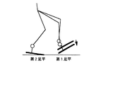
例えば、図42に示すように、両脚支持期に第1足平のつまさきが予期しない突起(段差)を踏んでしまうと、両脚支持期は、第1足平のつまさきが急激に下がりつつある時期であるので、つまさきで床を強く蹴ってしまい、第1足平床反力の鉛直成分が急増する。その結果、目標全床反力中心点(目標ZMP)まわりに急激に実全床反力モーメントが発生し、最悪の場合、両脚コンプライアンスによって姿勢を復元させようとしても間に合わずに転倒する。 For example, as shown in FIG. 42, if the toe of the first foot steps on an unexpected protrusion (step) during the support period of both legs, the toe of the first foot will drop rapidly during the support period of both legs. Since it is a certain time, the floor is strongly kicked by toes and the vertical component of the first foot floor reaction force increases rapidly. As a result, an actual total floor reaction force moment abruptly occurs around the target total floor reaction force center point (target ZMP), and in the worst case, even if an attempt is made to restore the posture by both-leg compliance, the vehicle falls over in time.
また、両脚支持期で倒れなかったとしても、その直後に第2足平を床から離したとき、目標全床反力中心点(目標ZMP)は第1足平のかかとにあるにもかかわらず、かかとが浮いているために実全床反力中心点はつまさきにあるので、目標全床反力中心点(目標ZMP)まわりにロボットを後に倒そうとする実全床反力モーメントが発生し、転倒する。 In addition, even if the body does not fall during the period when both legs are supported, when the second foot is released from the floor immediately after that, the target total floor reaction force center point (target ZMP) is on the heel of the first foot. Because the heel is floating, the actual total floor reaction force center point is in a pinch, so an actual total floor reaction force moment is generated that tries to tilt the robot later around the target total floor reaction force center point (target ZMP). And falls.
即ち、この両脚コンプライアンス制御は、長い距離でゆったりと変化する大域的な傾斜やうねりには対応できるが、足平の着地点の局所的な傾きや段差には対応できないと言える。 That is, it can be said that this both-legs compliance control can cope with the global inclination and the undulation that change slowly over a long distance, but cannot cope with the local inclination and the step of the landing point of the foot.
上記した両脚コンプライアンス制御とは別に、本出願人は、例えば下記の特許文献2において、2足歩行ロボットの足首部にゴムなどのばね特性を持った着地衝撃吸収機構を備えると共に、各足首まわりの実足平床反力モーメント成分を検出し、それを0にしようと各足首を回転させる足首コンプライアンス制御を提案している。
In addition to the above-described both-leg compliance control, the present applicant, for example, in
上記した問題点を解決するため、両脚コンプライアンス制御に加えて、この特許文献2で提案する技術(以下『足首コンプライアンス制御』という)を併用することもできる。 In order to solve the above problems, the technique proposed in Patent Document 2 (hereinafter referred to as “ankle compliance control”) can be used in combination with the both-leg compliance control.
その結果、足首コンプライアンス制御によって、図43に示すように、予期しなかった第1足平床反力モーメントを打ち消す方向に第1足首を回転させ、かかとも床に接地させることができる。従って、その後の片脚支持期になっても上述のようにロボットを転倒させることはない。
しかしながら、上記した両脚コンプライアンス制御および足首コンプライアンス制御を単純に併用するだけでは、2種の制御が干渉しあい、実全床反力と実各足平床反力が望ましい値からずれたり発振してしまう問題があった。 However, simply using both the leg compliance control and the ankle compliance control described above causes the two types of controls to interfere with each other, causing the actual total floor reaction force and the actual each floor floor reaction force to deviate or oscillate from the desired values. was there.
従って、この発明の目的は上記した不都合を解消することにあり、脚式移動ロボットに作用する実床反力を、干渉を生じることなく、容易かつ適切に制御することができる脚式移動ロボットの制御装置を提供することにある。 Accordingly, an object of the present invention is to eliminate the above-mentioned inconvenience, and a legged mobile robot that can easily and appropriately control the actual floor reaction force acting on the legged mobile robot without causing interference. It is to provide a control device.
この発明の第2の目的は、大域的なうねりや傾斜だけでなく、局所的な凹凸や傾斜なども含む予期しない床形状変化があっても、その影響をあまり受けずに脚式移動ロボットに作用する床反力を適切に制御することができる脚式移動ロボットの制御装置を提供することにある。 The second object of the present invention is to provide a legged mobile robot that is not greatly affected by unexpected floor shape changes including not only global undulation and inclination but also local unevenness and inclination. An object of the present invention is to provide a control device for a legged mobile robot capable of appropriately controlling an acting floor reaction force.
この発明の第3の目的は、脚式移動ロボットに作用する床反力を適切に制御することによって、脚式移動ロボットの姿勢安定化制御を容易にすることができる脚式移動ロボットの制御装置を提供することにある。 A third object of the present invention is to provide a control apparatus for a legged mobile robot that can facilitate posture stabilization control of the legged mobile robot by appropriately controlling the floor reaction force acting on the legged mobile robot. Is to provide.
この発明の第4の目的は、脚式移動ロボットに作用する床反力を適切に制御することによって、脚式移動ロボットが受ける着地衝撃を低減することができる脚式移動ロボットの制御装置を提供することにある。 A fourth object of the present invention is to provide a control apparatus for a legged mobile robot capable of reducing the landing impact received by the legged mobile robot by appropriately controlling the floor reaction force acting on the legged mobile robot. There is to do.
さらには、2足歩行ロボットは遊脚を振り出して歩行するが、それによってロボットの鉛直(重力)軸まわりの慣性モーメントが生じ、上体が鉛直軸まわりに回転振動し、それに起因して実各足平床反力モーメントの鉛直成分が振動する。上記振動の振幅が過大になると、実足平床反力モーメントのピーク値が摩擦の限界を超え、その瞬間に足底が滑り、ロボットはスピンする。スピンが大きいと、姿勢安定性を失って転倒する場合もある。従って、上記した制御に加え、そのような振動を低減することが望ましい。 In addition, biped robots walk with swinging swinging legs, which causes a moment of inertia around the vertical (gravity) axis of the robot, causing the upper body to oscillate around the vertical axis, resulting in each The vertical component of the foot floor reaction force moment vibrates. When the amplitude of the vibration becomes excessive, the peak value of the actual foot floor reaction force moment exceeds the limit of friction, and at that moment, the sole slips and the robot spins. If the spin is large, it may lose posture stability and fall. Therefore, it is desirable to reduce such vibrations in addition to the control described above.
従って、この発明の第5の目的は、脚式移動ロボットに作用する床反力を適切に制御すると共に、床反力モーメントの鉛直成分の振動を低減するようにした脚式移動ロボットの制御装置を提供することにある。 Accordingly, a fifth object of the present invention is to appropriately control the floor reaction force acting on the legged mobile robot and to reduce the vibration of the vertical component of the floor reaction force moment. Is to provide.
この発明の第6の目的は、さらに、脚式移動ロボットに作用する床反力を適切に制御することによって、脚式移動ロボットの接地性を高め、歩行時のスリップや前述のスピンを防止することができる脚式移動ロボットの制御装置を提供することにある。 The sixth object of the present invention is to further improve the ground contact of the legged mobile robot by appropriately controlling the floor reaction force acting on the legged mobile robot, thereby preventing slipping and the above-mentioned spin during walking. It is an object of the present invention to provide a control device for a legged mobile robot.
この発明の第7の目的は、脚式移動ロボットに作用する床反力を適切に制御することによって、脚式移動ロボットのアクチュエータの負荷を低減することができる脚式移動ロボットの制御装置を提供することにある。 A seventh object of the present invention is to provide a control device for a legged mobile robot that can reduce the load on the actuator of the legged mobile robot by appropriately controlling the floor reaction force acting on the legged mobile robot. There is to do.
上記の目的を達成するために、請求項1項にあっては、少なくとも基体と、記基体に第1の関節を介して連結されると共に、その先端に第2の関節を介して連結される足部を備えた複数本の脚部からなる脚式移動ロボットの制御装置において、前記ロボットの少なくとも前記足部の目標位置または姿勢を含む運動パターンと、前記ロボットに作用する全床反力の目標軌跡パターンからなる前記ロボットの目標歩容を生成する歩容生成手段、前記ロボットの姿勢安定化のための補償全床反力を決定する姿勢安定化補償全床反力決定手段、前記足部に作用する足部実床反力を検出する足部実床反力検出手段、前記目標歩容の全床反力と前記補償全床反力を少なくとも前記足部のそれぞれに分配する床反力分配手段、前記分配された目標歩容の全床反力と補償全床反力と前記検出された足部実床反力に基づいて前記目標歩容の足部の位置または姿勢を修正する修正手段、および前記修正された目標歩容の足部の位置または姿勢に基づいて前記第1および第2の関節を変位制御する関節変位制御手段を備える如く構成した。 In order to achieve the above object, according to the first aspect of the present invention, at least the base is connected to the base via the first joint and is connected to the tip of the base via the second joint. In a control apparatus for a legged mobile robot comprising a plurality of legs having a foot, a movement pattern including at least a target position or posture of the foot of the robot, and a target of a total floor reaction force acting on the robot A gait generating means for generating a target gait of the robot comprising a trajectory pattern, a posture stabilization compensating total floor reaction force determining means for determining a compensation total floor reaction force for posture stabilization of the robot, An actual foot reaction force detecting means for detecting an actual foot reaction force acting on the floor, a floor reaction force distribution for distributing the total floor reaction force of the target gait and the compensating total floor reaction force to at least each of the feet. Means, the whole floor of the distributed target gait Correction means for correcting the position or posture of the foot part of the target gait based on the force, the total floor reaction force and the detected actual floor reaction force of the foot, and the foot part of the corrected target gait It is configured to include joint displacement control means for controlling displacement of the first and second joints based on position or posture.
この請求項および以下の請求項で、「全床反力の目標パターン」は、少なくとも全床反力の中心点軌跡を少なくとも含む、全床反力に関する目標パターンを意味する。また「全床反力」は具体的には、脚部先端を介してロボットに作用する床反力の合力を意味する。尚、「足部」は具体的には、2足歩行ロボットの人間の足に似た足平を意味するが、それ以外の3足以上の脚式移動ロボットの脚部先端を含むと共に、人間の足と異なる爪などから主としてなるものも含む意味で使用する。 In this claim and the following claims, the “target pattern of the total floor reaction force” means a target pattern related to the total floor reaction force including at least the center point locus of the total floor reaction force. Further, the “total floor reaction force” specifically means the resultant force of the floor reaction force acting on the robot via the leg tips. “Foot part” specifically means a foot resembling the human foot of a biped robot, but includes the tip of the leg part of the other three or more legged mobile robots. It is also used in the sense that includes mainly nails, etc. that differ from the feet.
請求項2項に係る脚式移動ロボットにあっては、前記姿勢安定化補償全床反力決定手段は、前記姿勢安定化補償全床反力を、少なくとも前記ロボットの傾き偏差に基づいて求める如く構成した。
In the legged mobile robot according to
請求項3項に係る脚式移動ロボットの制御装置にあっては、前記姿勢安定化補償全床反力決定手段は、前記姿勢安定化補償全床反力を、少なくとも前記ロボットのヨーレートに基づいて求める如く構成した。
In the control apparatus for a legged mobile robot according to
請求項4項に係る脚式移動ロボットの制御装置にあっては、前記姿勢安定化補償全床反力決定手段は、前記姿勢安定化補償全床反力を、少なくとも前記ロボットの目標経路からのずれに基づいて求める如く構成した。
In the control device for a legged mobile robot according to
請求項5項に係る脚式移動ロボットの制御装置にあっては、前記姿勢安定化補償全床反力決定手段は、前記姿勢安定化補償全床反力の中の所定の成分を零またはその近傍に設定する如く構成した。 In the control device for a legged mobile robot according to claim 5, the posture stabilization compensation total floor reaction force determining means sets a predetermined component in the posture stabilization compensation total floor reaction force to zero or the predetermined component. It was configured to be set in the vicinity.
請求項6項に係る脚式移動ロボットの制御装置にあっては、前記修正手段は、前記ロボットの姿勢偏差に基づいて前記目標歩容の足部の位置または姿勢をさらに修正する如く構成した。 In the control device for a legged mobile robot according to claim 6, the correction means is configured to further correct the position or posture of the foot of the target gait based on the posture deviation of the robot.
請求項1項にあっては、脚式移動ロボットに作用する床反力を、干渉を生じることなく、容易かつ適切に制御することができる。換言すれば、先に提案した両脚コンプライアンス制御および足首コンプライアンス制御の併用に近い制御を行っても、制御の干渉がなく、実全床反力と実各足平床反力が望ましい値からずれたり発振することがない。また、足部の修正量を一層適切に配分することができるので、姿勢安定化のためのより大きな復元力とより高い接地性を得ることができる。 According to the first aspect, the floor reaction force acting on the legged mobile robot can be easily and appropriately controlled without causing interference. In other words, even if the control similar to the combined use of the two-leg compliance control and the ankle compliance control previously proposed is performed, there is no control interference, and the actual total floor reaction force and each actual floor reaction force deviate from desired values or oscillate. There is nothing to do. In addition, since the correction amount of the foot can be more appropriately distributed, it is possible to obtain a greater restoring force and a higher grounding property for posture stabilization.
即ち、大域的なうねりや傾斜だけでなく、局所的な凹凸や傾斜なども含む予期しない床形状変化があっても、その影響をあまり受けずに脚式移動ロボットに作用する床反力を適切に制御することができる。 In other words, the floor reaction force that acts on the legged mobile robot without being affected by an unexpected floor shape change including not only global undulation and inclination but also local unevenness and inclination is appropriate. Can be controlled.
また、脚式移動ロボットの姿勢安定化制御を容易に実現できると共に、脚式移動ロボットが受ける着地衝撃を低減することができ、脚式移動ロボットの接地性を高め、歩行時のスリップやスピンを防止することができる。さらに、脚式移動ロボットのアクチュエータの負荷を低減することができる。 In addition, the legged mobile robot's posture stabilization control can be easily realized, the landing impact received by the legged mobile robot can be reduced, the grounding performance of the legged mobile robot can be improved, and slip and spin during walking can be reduced. Can be prevented. Furthermore, the load on the actuator of the legged mobile robot can be reduced.
請求項2項にあっては、姿勢安定化能力を一層向上させることができる。 In the second aspect, the posture stabilization ability can be further improved.
請求項3項にあっては、前記したと同様の作用効果を得ることができると共に、ロボットのスピンあるいはスリップを防止することができ、姿勢安定化能力を一層向上させることができる。従って、摩擦係数が低い路面を歩行するときも、スピンあるいはスリップを効果的に防止することができ、安定な姿勢で歩行を継続させることができる。 According to the third aspect, it is possible to obtain the same effects as described above, to prevent the robot from spinning or slipping, and to further improve the posture stabilization ability. Therefore, even when walking on a road surface with a low friction coefficient, spin or slip can be effectively prevented and walking can be continued in a stable posture.
請求項4項にあっては、前記したと同様の作用効果を得ることができると共に、目標経路に沿って安定した姿勢で歩行を継続することができる。 According to the fourth aspect, it is possible to obtain the same operational effects as described above and to continue walking in a stable posture along the target route.
請求項5項にあっては、前記したと同様の作用効果を得ることができると共に、ヨーレートを検出しなくてもロボットのスピンあるいはスリップをかなりの程度まで防止することができ、その意味で姿勢安定化能力を一層向上させることができる。 According to the fifth aspect, it is possible to obtain the same effect as described above, and to prevent the robot from spinning or slipping to a considerable extent without detecting the yaw rate. Stabilization ability can be further improved.
請求項6項にあっては、前記したと同様の作用効果を得ることができると共に、ロボットに作用する実床反力を一層精度良く制御することができる。 According to the sixth aspect, it is possible to obtain the same effect as described above, and to control the actual floor reaction force acting on the robot with higher accuracy.
以下、添付図面を参照してこの発明に係る脚式移動ロボットの制御装置を説明する。尚、脚式移動ロボットとしては2足歩行ロボットを例にとる。 Hereinafter, a legged mobile robot controller according to the present invention will be described with reference to the accompanying drawings. As a legged mobile robot, a biped walking robot is taken as an example.
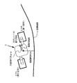
図1はその脚式移動ロボットの制御装置を全体的に示す概略図である。 FIG. 1 is a schematic diagram showing the control apparatus for the legged mobile robot as a whole.
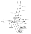
図示の如く、2足歩行ロボット1は左右それぞれの脚部リンク2に6個の関節を備える(理解の便宜のために各関節をそれを駆動する電動モータで示す)。6個の関節は上から順に、股(腰部)の脚部回旋用の関節10R,10L(右側をR、左側をLとする。以下同じ)、股(腰部)のロール方向(Y軸まわり)の関節12R,12L、同ピッチ方向(X軸まわり)の関節14R,14L、膝部のロール方向の関節16R,16L、足首のロール方向の関節18R,18L、同ピッチ方向の関節20R,20Lから構成される。
As shown in the figure, the
関節18R(L),20R(L)の下部には足平(足部)22R,22Lが取着されると共に、最上位には上体(基体)24が設けられ、その内部にマイクロコンピュータからなる制御ユニット26(後述)などが格納される。上記において股関節(あるいは腰関節)は関節10R(L),12R(L),14R(L)から、足関節(足首関節)は関節18R(L),20R(L)から構成される。また股関節と膝関節とは大腿リンク28R,28L、膝関節と足関節とは下腿リンク30R,30Lで連結される。
Foot feet (foot portions) 22R and 22L are attached to the lower portions of the
上記の構成により、脚部リンク2は左右の足についてそれぞれ6つの自由度を与えられ、歩行中にこれらの6*2=12個の関節を適宜な角度で駆動することで、足全体に所望の動きを与えることができ、任意に3次元空間を歩行させることができる(この明細書で「*」はスカラに対する演算としては乗算を、ベクトルに対する演算としては外積を示す)。
With the above configuration, the
尚、この明細書で後述する上体の位置およびその速度は、上体24の所定位置、具体的には上体24の重心位置などの代表点の位置およびその移動速度を意味する。
Note that the position of the upper body and its speed described later in this specification mean a predetermined position of the
図1に示す如く、足関節の下方には公知の6軸力センサ44が取着され、力の3方向成分Fx,Fy,Fzとモーメントの3方向成分Mx,My,Mzとを測定し、足部の着地の有無および床反力(接地荷重)などを検出する。また、上体24には傾斜センサ60が設置され、Z軸(鉛直方向(重力方向))に対する傾きとその角速度を検出する。また各関節の電動モータには、その回転量を検出するロータリエンコーダが設けられる。
As shown in FIG. 1, a known six-
図2に示すように、足平22R(L)の上方には、ばね機構32が装備されると共に、足底にはゴムなどからなる足底弾性体34が貼られる。ばね機構32は具体的には、足平22R(L)に取り付けられた方形状のガイド部材と、足首関節18R(L)および6軸力センサ44側に取り付けられ、前記ガイド部材に弾性材を介して微動自在に収納されるピストン状部材とからなる。
As shown in FIG. 2, a
図中に実線で表示された足平22R(L)は、床反力を受けていないときの状態を示す。床反力を受けるとバネ機構32と足底弾性体34がたわみ、足平は図中に点線で表示された位置・姿勢に移る。この構造は、着地衝撃を緩和するためだけでなく、制御性を高めるためにも重要なものである。尚、その詳細は前記した特開平5−305584号に記載されているので、詳細な説明は省略する。
A
更に、図1では図示を省略するが、2足歩行ロボット1の適宜な位置にはジョイスティック62が設けられ、外部から必要に応じて直進歩行しているロボットを旋回させるなど歩容に対する要求を入力できるように構成される。
Further, although not shown in FIG. 1, a joystick 62 is provided at an appropriate position of the
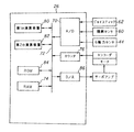
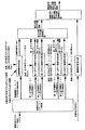
図3は制御ユニット26の詳細を示すブロック図であり、マイクロ・コンピュータから構成される。そこにおいて傾斜センサ60などの出力はA/D変換器70でデジタル値に変換され、その出力はバス72を介してRAM74に送られる。また各電動モータに隣接して配置されるエンコーダの出力はカウンタ76を介してRAM74内に入力される。
FIG. 3 is a block diagram showing the details of the
制御ユニット内にはCPUからなる第1、第2の演算装置80,82が設けられており、第1の演算装置80は後述の如く、ROM84に格納されている歩容に基づいて後述の如く関節角変位指令を算出し、RAM74に送出する。また第2の演算装置82はRAM74からその指令と検出された実測値とを読み出し、各関節の駆動に必要な制御値を算出してD/A変換器86とサーボアンプを介して各関節を駆動する電動モータに出力する。
The control unit is provided with first and second
ここで、この明細書および図面で使用する用語について定義する(尚、定義しない用語に関しては、本出願人が前記した技術とは別に提案した出願(特願平8−214261号)で使用した定義に従う)。 Here, terms used in this specification and drawings are defined (for terms that are not defined, definitions used in an application (Japanese Patent Application No. 8-214261) proposed separately from the technique described above by the present applicant). Follow).
『歩容』は、ロボット工学における一般的な定義と異なり、目標運動パターンと床反力パターンを合わせたものを指称する意味で使用する。但し、床反力パターンとしては、例えば『ZMP軌跡だけ』というように、部分情報であっても良い。そのため、目標運動パターンだけを出力して床反力パターンに関する情報を出力しない装置に対して「歩容生成装置」と言う言葉を用いない。 Unlike the general definition in robot engineering, “gait” is used to refer to a combination of a target motion pattern and a floor reaction force pattern. However, the floor reaction force pattern may be partial information such as “ZMP locus only”. Therefore, the term “gait generator” is not used for a device that outputs only the target motion pattern and does not output information on the floor reaction force pattern.
各脚には、通し番号をつける。第n脚に作用する床反力を第n足平床反力という(n:1または2。以下同じ)。全脚に作用する床反力を合成したものを全床反力という(ロボット工学では一般的には床反力と呼ばれるが、足平床反力と区別するためにここでは『全床反力』という)。 Each leg is given a serial number. The floor reaction force acting on the nth leg is referred to as the nth foot floor reaction force (n: 1 or 2, hereinafter the same). The total floor reaction force is a combination of floor reaction forces acting on all legs (generally called floor reaction forces in robotics, but here we will refer to them as “total floor reaction forces” to distinguish them from foot floor reaction forces. Called).
足平床反力は作用点とそこにかかる力と力のモーメントによって表現され、同一の足平床反力に対して、表現の組み合わせは無限通りある。その中には、鉛直軸まわりの成分を除くモーメント成分が0でかつ作用点が床面上にある表記が存在する。この表現における作用点を、ここでは足平床反力中心点という(本出願人が別途提案した後述する特開平6−79657号では『接地圧重心点』と称した)。 The foot floor reaction force is expressed by the point of action, the force applied to it, and the moment of force. For the same foot floor reaction force, there are infinite combinations of expressions. Among them, there is a notation that the moment component excluding the component around the vertical axis is zero and the action point is on the floor surface. The action point in this expression is herein referred to as the foot floor reaction force center point (referred to as “ground pressure center of gravity point” in Japanese Patent Laid-Open No. 6-79657, which will be described later separately proposed by the present applicant).
同様に、全床反力は作用点とそこにかかる力と力のモーメントによって表現され、同一の全床反力に対して表現の組み合わせは無限通りある。その中には、鉛直軸まわりの成分を除くモーメント成分が0でかつ作用点が床面上にある表現が存在する。この表現における作用点を、ここでは全床反力中心点という。 Similarly, the total floor reaction force is expressed by the point of action, the force applied thereto, and the moment of the force, and there are infinite combinations of expressions for the same total floor reaction force. Among them, there is an expression in which the moment component excluding the component around the vertical axis is 0 and the action point is on the floor surface. The action point in this expression is referred to herein as the center point of the total floor reaction force.
全床反力の目標値を目標全床反力という。目標全床反力は、通常、目標運動パターンに対して動力学的に平衡する全床反力である。従って、通常、目標全床反力中心点は、目標ZMPに一致する。 The target value of the total floor reaction force is called the target total floor reaction force. The target total floor reaction force is usually a total floor reaction force that is dynamically balanced with respect to the target motion pattern. Therefore, the target total floor reaction force central point usually coincides with the target ZMP.
尚、始めに触れたように、目標ZMP(Zero Moment Point )は次のように定義される。即ち、目標運動パターンによって発生する慣性力と重力の合力を動力学的に求め、これが床面上のある点に作用するモーメントが、鉛直軸まわりの成分を除き0であるならば、その点を目標ZMP(Zero Moment Point)という。目標ZMPは、合力の垂直方向力成分が0でない限り、一義的に求められる。以下の説明では、理解しやすくするために、目標ZMPという言葉を用いる場合もあるが、厳密には目標全床反力中心点と言うべき箇所が多い。 As mentioned at the beginning, the target ZMP (Zero Moment Point) is defined as follows. That is, if the inertial force generated by the target motion pattern and the resultant force of gravity are determined kinetically and the moment acting on a certain point on the floor is zero except for the component around the vertical axis, that point is This is called a target ZMP (Zero Moment Point). The target ZMP is uniquely determined unless the vertical force component of the resultant force is zero. In the following description, for the sake of easy understanding, the term target ZMP may be used, but strictly speaking, there are many points that should be referred to as the target total floor reaction force central point.
各足平床反力の目標値を目標各足平床反力という。但し、目標全床反力とは異なり、目標運動パターンが決まっていても目標各足平床反力は一義的には決定されない。実際のロボットに作用する全床反力を実全床反力という。実際のロボットに作用する各足平床反力を実各足平床反力という。 The target value of each foot floor reaction force is referred to as a target foot floor reaction force. However, unlike the desired total floor reaction force, the desired foot floor reaction force is not uniquely determined even if the desired movement pattern is determined. The total floor reaction force acting on the actual robot is called the actual total floor reaction force. Each foot floor reaction force acting on an actual robot is called an actual foot floor reaction force.
ここで、この発明の課題について再説すると、局所的な傾きや段差に対して先に提案した両脚コンプライアンス制御では良好な姿勢安定性を得ることが困難であると共に、その不都合は足首コンプライアンス制御を用いれば解消することができるが、両者を単純に併用するだけでは干渉しあい、実全床反力と実各足平床反力が望ましい値からずれたり、発振する不都合があった。 Here, to reiterate the problem of the present invention, it is difficult to obtain good posture stability with the two-leg compliance control previously proposed for local inclination and step, and the disadvantage is that ankle compliance control is used. However, there is a disadvantage that the actual total floor reaction force and the actual foot floor reaction force deviate from desired values or oscillate.
その問題点を先の図40に示す状況で説明すると、第1足平はかかとに予期しなかった過大な床反力を受けているため、第1足首のまわりに過大な実足平床反力モーメントが発生する。足首コンプライアンス制御は、このモーメントを0にしようと第1足首を図43に示すように回転させる。 Explaining the problem in the situation shown in FIG. 40, since the first foot receives an unexpected excessive floor reaction force on the heel, an excessive actual foot floor reaction force is generated around the first ankle. A moment is generated. In ankle compliance control, the first ankle is rotated as shown in FIG. 43 in order to reduce this moment.
しかしながら、足首の回転によって、第1足平のかかと位置が高くなるので、第1足平床反力の鉛直成分が減少する。この結果、目標全床反力中心点(目標ZMP)まわりの実全床反力モーメントが変化する。これは、両脚コンプライアンス制御の制御量である実全床反力モーメントが、足首コンプライアンス制御に干渉されることを意味する。 However, since the heel position of the first foot increases due to the rotation of the ankle, the vertical component of the first foot floor reaction force decreases. As a result, the actual total floor reaction force moment around the target total floor reaction force central point (target ZMP) changes. This means that the actual total floor reaction force moment, which is the control amount of the both-leg compliance control, is interfered with the ankle compliance control.
従って、足首コンプライアンス制御による干渉を考慮しないで、両脚コンプライアンス制御を、足首コンプライアンス制御がない場合と同様に働かせると、目標全床反力中心点(目標ZMP)まわりの実全床反力モーメントが0からずれたり、干渉による振動や発振が生じる。 Accordingly, if both legs compliance control is operated in the same manner as without ankle compliance control without considering interference due to ankle compliance control, the actual total floor reaction force moment around the target total floor reaction force central point (target ZMP) is 0. Or vibration or oscillation due to interference occurs.
それを防止する方法のひとつとして、両脚コンプライアンス制御と足首コンプライアンス制御の間の干渉量を求め、それを打ち消すような操作量を加えることによって干渉しないようにすることが考えられるが、歩行中は姿勢が時々刻々と変化し、干渉関係も時々刻々と変化するため、この手法で干渉を回避することは極めて難しい。 One way to prevent this is to calculate the amount of interference between the two-leg compliance control and the ankle compliance control, and to avoid interference by adding an operation amount that cancels it. However, it is extremely difficult to avoid interference with this method because the interference relationship changes every moment.
また、図43に示す状況では、第1足平が接触している床は想定していた床よりも登り傾斜なので、第1足平は、目標歩容よりもつまさきを上げるべきである。それにもかかわらず、足首コンプライアンス制御によりつまさきが下がってしまうことは、足首コンプライアンス制御が適切に作用していないとも言える。 In addition, in the situation shown in FIG. 43, the floor with which the first foot is in contact is climbing more inclined than the assumed floor, so the first foot should be better than the target gait. Nevertheless, it can be said that the ankle compliance control does not work properly if the ankle compliance control lowers the tow.
以上のように、足首コンプライアンス制御は足平の着地点の局所的な床の傾きや段差には効果があるが、長い距離でゆったりと変化する傾斜やうねりには、却って悪影響を与える場合がある。 As described above, ankle compliance control is effective for local floor inclinations and steps at the landing point of the foot, but it may adversely affect inclinations and undulations that change slowly over long distances. .
従って、実施例に係る装置においては、脚式移動ロボットに作用する床反力、より具体的には、目標全床反力中心点まわりの実全床反力モーメントと、目標各足平床反力中心点まわりの実各足平床反力モーメントを容易かつ適切に制御できるようにした。 Therefore, in the apparatus according to the embodiment, the floor reaction force acting on the legged mobile robot, more specifically, the actual total floor reaction force moment about the target total floor reaction force center point, and the desired foot floor reaction force. Each foot floor reaction force moment around the center point can be controlled easily and appropriately.
また、それによって大域的なうねりや傾斜だけでなく、局所的な凹凸や傾斜なども含む予期しない床形状変化があっても、その影響をあまり受けずに安定した姿勢でロボットを歩行継続させるようにした。 In addition to this, even if there is an unexpected floor shape change including not only global waviness and inclination but also local unevenness and inclination, the robot should continue to walk in a stable posture without being affected by it. I made it.
図4は、この実施例に係る脚式移動ロボットの制御装置(主として図3の第1の演算装置80に相当)の構成および動作を機能的に示すブロック図である。以下、図4を参照してこの装置の全体構成を概説する。 FIG. 4 is a block diagram functionally showing the configuration and operation of the control device (mainly equivalent to the first arithmetic device 80 of FIG. 3) of the legged mobile robot according to this embodiment. The overall configuration of this apparatus will be outlined below with reference to FIG.
この装置は歩容生成器を備え、歩容生成器は目標歩容を生成し、出力する。目標歩容は、前述の定義の通り、目標運動パターンと目標床反力パターン、より具体的には目標上体位置・姿勢軌道、目標足平位置・姿勢軌道、目標全床反力中心点(目標ZMP)軌道および目標全床反力軌道からなる。目標床反力パターンは、このように、目標全床反力中心点軌跡を含む(後述する機構変形補償を行わないならば、目標床反力パターンとしては目標全床反力中心点軌跡だけでも良い)。 The apparatus includes a gait generator, and the gait generator generates and outputs a target gait. The target gait is the target motion pattern and target floor reaction force pattern, more specifically, the target body position / posture trajectory, target foot position / posture trajectory, target total floor reaction force center point ( Target ZMP) trajectory and target total floor reaction force trajectory. Thus, the target floor reaction force pattern includes the target total floor reaction force center point locus (if the mechanism deformation compensation described later is not performed, the target floor reaction force center point locus alone is used as the target floor reaction force center pattern. good).
この実施例において歩容生成器が出力する目標全床反力は、目標運動パターンに対して動力学的に平衡する全床反力である。従って、目標全床反力中心点は、目標ZMPに一致する。 In this embodiment, the desired total floor reaction force output by the gait generator is a total floor reaction force that is dynamically balanced with respect to the desired motion pattern. Accordingly, the target total floor reaction force central point coincides with the target ZMP.
図5にロボット1が平地を歩行するときの目標運動パターンの一例を示す。これに対応する目標ZMP軌道の床面上軌跡を図6に、タイム・チャートを図7に示す。この歩容の期間に床に接触したままの足平を、第1足平、もう一方を第2足平ということとする。尚、歩容生成器の詳細は先に提案した特願平8−214261号に詳細に述べられているので、これ以上の説明は省略する。
FIG. 5 shows an example of a target motion pattern when the
図4の説明に戻ると、この装置は目標床反力分配器を備え、目標床反力分配器は、目標全床反力中心点(目標ZMP)と目標足平位置・姿勢を主な入力とし、目標各足平床反力中心点を決定して出力する。実際には、歩容生成器から歩容のパラメータ(例えば、両脚支持期の時間や遊脚足平の目標着地位置など)や、歩容の時期・時刻(例えば、現在時刻が両脚支持期の初めから0.1secであるなど)などの情報も必要に応じて取り込む。 Returning to the explanation of FIG. 4, this apparatus includes a target floor reaction force distributor, and the target floor reaction force distributor mainly inputs a target total floor reaction force center point (target ZMP) and a target foot position / posture. The target foot floor reaction force center point is determined and output. Actually, from the gait generator, the gait parameters (for example, the time of both leg support period and the target landing position of the free leg foot) and the time and time of the gait (for example, the current time of Information such as 0.1 sec from the beginning) is also imported if necessary.
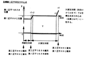
図5に示すような歩容に対して、目標床反力分配器は、目標各足平床反力中心点が以下の条件を満足するように設定する。
条件1)目標各足平床反力中心点軌跡は連続である。
条件2)両脚支持期では、目標第1足平床反力中心点はかかとに、目標第2足平床反力中心点はつまさきに存在する。
条件3)このとき目標第1足平床反力中心点と目標第2足平床反力中心点を結ぶ線分上に、目標全床反力中心点が存在する。
条件4)片脚支持期では、目標第1足平床反力中心点は、目標全床反力中心点に一致する。
条件5)片脚支持期の間に、目標第2足平床反力中心点は、つまさきからかかとに移動する。
For the gait as shown in FIG. 5, the desired floor reaction force distributor is set so that each desired foot floor reaction force center point satisfies the following conditions.
Condition 1) Target foot floor reaction force center point locus is continuous.
Condition 2) In the both-leg support period, the target first foot floor reaction force center point exists on the heel, and the target second foot floor reaction force center point exists on the heel.
Condition 3) At this time, the target total floor reaction force center point exists on a line segment connecting the target first foot floor reaction force center point and the target second foot floor reaction force center point.
Condition 4) In the one leg support period, the target first foot floor reaction force central point coincides with the target total floor reaction force central point.
Condition 5) During the one-leg support period, the target second foot floor reaction force central point moves from the toe to the heel.
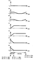
これら条件を満足する目標第1足平床反力中心点軌跡のタイム・チャートを図8に、目標第2足平床反力中心点軌跡のタイム・チャートを図9に示す。尚、この図では足首(関節18,20R(L))から足平22R(L)への垂直投影点を原点とし、図1に示すように足平前方向をX軸の正の向き、足平左方向をY軸の正の向きにとる。
FIG. 8 shows a time chart of the target first foot floor reaction force central point locus satisfying these conditions, and FIG. 9 shows a time chart of the target second foot floor reaction force central point locus. In this figure, the vertical projection point from the ankle (joint 18, 20R (L)) to the
目標床反力分配器は、更に、付随的ではあるが、目標各足平床反力も決定して出力する。目標各足平床反力は、ばね機構32などのたわみ補償のために必要である。
The target floor reaction force distributor further determines and outputs each foot floor reaction force, although it is incidental. Each desired foot floor reaction force is necessary to compensate for deflection of the
次式を用いて上記のように設定された目標各足平床反力中心点に対応する目標各床反力を決定すれば、目標各足平床反力の合力は目標全床反力に一致しなければならないと言う条件を満足する。 If the target floor reaction force corresponding to the target foot floor reaction force center point set as described above is determined using the following equation, the resultant force of the target foot floor reaction force matches the target total floor reaction force. Satisfy the condition of having to.
目標第1足平床反力=目標全床反力*(目標第2足平床反力中心点と目標ZMPの距離)/(目標第1足平床反力中心点と目標第2足平床反力中心点の距離) 目標第2足平床反力=目標全床反力*(目標第1足平床反力中心点と目標ZMPの距離)/(目標第1足平床反力中心点と目標第2足平床反力中心点の距離)
・・・式1
Target first foot floor reaction force = Target total floor reaction force * (Distance between target second foot floor reaction force center point and target ZMP) / (Target first foot floor reaction force center point and target second foot floor reaction force center) Point distance) Target second foot floor reaction force = Target total floor reaction force * (Distance between target first foot floor reaction force center point and target ZMP) / (Target first foot floor reaction force center point and target second foot) Flat floor reaction force center point distance)
...
このように求めた目標各足平床反力は連続的に変化するので、衝撃の少ない歩行を実現するために適している。尚、上記の詳細は本出願人が別途提案した技術(特開平6−79657号)に記述されている。 Since each desired foot floor reaction force obtained in this way changes continuously, it is suitable for realizing walking with less impact. The details described above are described in a technique (Japanese Patent Laid-Open No. 6-79657) separately proposed by the present applicant.
図4の説明に戻ると、この装置は姿勢安定化制御演算部を備え、姿勢安定化制御演算部はロボットのセンサ情報に基づいてロボットの状態を推定し、補償全床反力を算出する。即ち、実際にロボットが歩行あるいは直立しているときなどには後述する変位コントローラによって実関節変位を目標関節変位に完全に追従させることができたとしても、ロボットの位置・姿勢は必ずしも望ましい位置・姿勢にならない。 Returning to the description of FIG. 4, this apparatus includes a posture stabilization control calculation unit, which estimates the state of the robot based on the sensor information of the robot and calculates a compensated total floor reaction force. That is, when the robot is actually walking or standing upright, even if the actual joint displacement can be made to completely follow the target joint displacement by the displacement controller described later, the position / posture of the robot is not necessarily the desired position / posture. I can't take a posture.
ロボットの姿勢を長期的に安定化させるためには、ロボットを望ましい位置・姿勢に復元させるために必要な力とモーメントを求め、これを目標全床反力中心点(目標ZMP)を作用点として付加的に発生させる必要がある。この付加的な力とモーメントを補償全床反力という。また、補償全床反力のモーメント成分を補償全床反力モーメントという。 To stabilize the robot's posture in the long term, obtain the force and moment necessary to restore the robot to the desired position and posture, and use this as the target point of the total floor reaction force center (target ZMP). It must be generated additionally. This additional force and moment is called compensated total floor reaction force. The moment component of the compensated total floor reaction force is referred to as a compensated total floor reaction force moment.
尚、脚式移動ロボットの目標歩容が床反力以外の反力を環境から受けるように想定し、それを例えば、目標対象物反力と称し、先に述べた目標ZMPの定義を次のように拡張しても良い。即ち、目標運動パターンによって発生する慣性力と重力と目標対象物反力の合力を動力学的に求め、それが床面上のある点に作用するモーメントが、鉛直軸まわりの成分を除いて零であるならば、その点を改めて目標ZMPとするようにしても良い。 It is assumed that the target gait of the legged mobile robot receives a reaction force other than the floor reaction force from the environment, which is referred to as a target object reaction force, for example, and the definition of the target ZMP described above is as follows: You may extend as follows. That is, the resultant force of the inertial force, gravity and target object reaction force generated by the target motion pattern is obtained dynamically, and the moment that acts on a certain point on the floor surface is zero except for the component around the vertical axis. If so, this point may be set as the target ZMP again.
もし、ロボット1が完全剛体であって、変位コントローラによって実関節変位を目標関節変位に完全に追従させることができたと仮定すると、足平のばね機構32および足底弾性体34のたわみによって生じるロボット全体の位置・姿勢の摂動的な運動は、以下の6自由度に分解できる。
If it is assumed that the
モード1)目標全床反力中心点(目標ZMP)を中心とした前後軸まわり回転(即ち、左右傾き)
モード2)目標全床反力中心点(目標ZMP)を中心とした左右軸まわり回転(即ち、前後傾き)
モード3)目標全床反力中心点(目標ZMP)を中心とした鉛直軸まわり回転(即ち、スピン)
モード4)前後平行移動揺れ
モード5)左右平行移動揺れ
モード6)上下平行移動揺れ
Mode 1) Rotation around the longitudinal axis about the target floor reaction force center point (target ZMP) (ie, tilting left and right)
Mode 2) Rotation around the left / right axis about the target floor reaction force center point (target ZMP) (ie, forward / backward tilt)
Mode 3) Rotation around the vertical axis around the target total floor reaction force center point (target ZMP) (ie, spin)
Mode 4) Forward / backward translation shaking mode 5) Left / right translational shaking mode 6) Vertical translational shaking
この内で、モード4とモード5は、足平のばね機構32および弾性体34が前後左右方向のせん断力を受けてたわむことによって発生するものである。ばね機構32および足底弾性体34は剪断方向の剛性が高いように製作するので、この揺れは極めて少なく、歩行に及ぼす悪影響はほとんどない。
Of these modes,
残り4自由度の内、モード3とモード6はこの発明に直接の関連を有しないので、この実施例および後述する第2の実施例ではモード1とモード2に対する制御だけを行うこととする。モード1とモード2に対する制御は、これがないとほとんどの場合ロボットが転倒するので、重要度は極めて高い。尚、第3の実施例でモード3に対する制御を行う。
Of the remaining four degrees of freedom,
モード1を制御するための操作量は、補償全床反力の前後軸(X軸)まわりモーメント成分である。モード2を制御するための操作量は、補償全床反力の左右軸(Y軸)まわりモーメント成分である。従って、補償全床反力の成分の内、前後軸方向モーメント成分と左右軸方向モーメント成分だけを求めれば良い。他の成分は、この実施例(および第2の実施例)では用いないので0で良い。
The operation amount for controlling the
尚、以降は次の定義に従う。即ち、補償全床反力のモーメント成分を補償全床反力モーメントMdmd(詳しくは目標全床反力中心点(目標ZMP)まわりの補償全床反力モーメントMdmd)という。図5に示す如く、ロボットの前方向をX軸、左横方向をY軸、上方向をZ軸にとり、第1足平の足首直下の床面上の点を原点とした座標系を支持脚座標系と呼び、断らない限り、位置、力およびモーメントはこの座標系で表現されるものとする。また、MdmdのX成分をMdmdx、Y成分をMdmdy、Z成分をMdmdzと記述する。上体24の傾斜偏差(即ち、実上体傾斜−目標上体傾斜)θerr のX成分をθerrx, Y成分をθerry、これらの時間微分値を(dθerrx / dt),(dθerry / dt)と記述する。 The following definition follows. That is, the moment component of the compensated total floor reaction force is referred to as a compensated total floor reaction force moment Mdmd (specifically, the compensated total floor reaction force moment Mdmd around the target total floor reaction force central point (target ZMP)). As shown in FIG. 5, the robot's forward direction is the X-axis, the left lateral direction is the Y-axis, the upward direction is the Z-axis, and the coordinate system with the point on the floor just below the ankle of the first foot as the origin is the support leg. This is called the coordinate system, and unless otherwise specified, the position, force and moment are expressed in this coordinate system. Further, the X component of Mdmd is described as Mdmdx, the Y component as Mdmdy, and the Z component as Mdmdz. The tilt deviation of the body 24 (ie, the actual body tilt—the target body tilt) θerr is described as θerrx, the Y component as θerry, and their time differential values as (dθerrx / dt) and (dθerry / dt). To do.
MdmdxおよびMdmdyは、例えば次式の制御則によって決定される。
Mdmdx = - Kthxθerrx - Kwx (dθerrx / dt)
Mdmdy = - Kthyθerry - Kwy (dθerry / dt)
・・・式2
ここで、Kthx,Kthy,KwxおよびKwyは、上体傾斜安定化制御ゲインである。
Mdmdx and Mdmdy are determined, for example, by the following control law.
Mdmdx =-Kthxθerrx-Kwx (dθerrx / dt)
Mdmdy =-Kthyθerry-Kwy (dθerry / dt)
...
Here, Kthx, Kthy, Kwx, and Kwy are body tilt stabilization control gains.
後述する複合コンプライアンス動作決定部は、目標全床反力と補償全床反力の合力に実全床反力を一致させようと働く。 The composite compliance operation determination unit described later works to make the actual total floor reaction force coincide with the resultant force of the target total floor reaction force and the compensated total floor reaction force.
図4の説明に戻ると、この装置は実各足平床反力検出器を備え、実各足平床反力検出器は、6軸力センサ44によって実各足平床反力(その合力が実全床反力)を検出する。更に、関節のエンコーダによって検出される実変位(あるいは変位指令)に基づき、上体に固定された座標系に対する各足平の相対位置・姿勢を算出し、それによって6軸力センサ44の検出値を座標変換し、上体に固定された座標系で表現された実各足平床反力を算出した後、更に、支持脚座標系に変換する。
Returning to the description of FIG. 4, this apparatus is provided with actual foot floor reaction force detectors, and each actual foot floor reaction force detector is detected by the 6-
この装置はロボット幾何学モデル(逆キネマティクス演算部)を備え、ロボット幾何学モデルは、上体位置・姿勢と足平位置・姿勢を入力されると、それらを満足する各関節変位を算出する。この実施例におけるロボット1のような1脚あたりの関節自由度が6である場合には、各関節変位は一義的に求まる。
This device is equipped with a robot geometric model (inverse kinematics calculation unit). When a body position / posture and a foot position / posture are input, the robot geometric model calculates joint displacements that satisfy them. . When the degree of joint freedom per leg is 6 as in the
この実施例では逆キネマティクスの解の式を直接的に求めておき、式に上体位置・姿勢と足平位置・姿勢を代入するだけで各関節変位を得るようにした。即ち、ロボット幾何学モデルは、目標上体位置・姿勢と複合コンプライアンス動作決定部で修正された修正目標足平位置・姿勢軌道(機構変形補償入り修正目標足平位置・姿勢軌道)を入力し、それらから12個の関節(10R(L)など)の関節変位指令(値)を算出する。 In this embodiment, the inverse kinematics solution equation is obtained directly, and each joint displacement is obtained simply by substituting the body position / posture and the foot position / posture into the equation. That is, the robot geometric model inputs the target body position / posture and the corrected target foot position / posture trajectory (corrected target foot position / posture trajectory with mechanism deformation compensation) corrected by the composite compliance action determination unit. From them, joint displacement commands (values) of 12 joints (10R (L), etc.) are calculated.
この装置は変位コントローラ(前記した第2の演算装置82に同じ)を備え、変位コントローラは、ロボット幾何学モデル(逆キネマティクス演算部)で算出された関節変位指令(値)を目標値としてロボット1の12個の関節の変位を追従制御する。 This apparatus includes a displacement controller (same as the above-described second arithmetic unit 82). The displacement controller uses a joint displacement command (value) calculated by a robot geometric model (inverse kinematics arithmetic unit) as a target value. The follow-up control of the displacement of 12 joints of 1 is performed.
この装置は前記複合コンプライアンス動作決定部を備え、複合コンプライアンス動作決定部は以下の2つの要求を満足させようと、目標足平位置・姿勢軌道を修正する。 This apparatus includes the composite compliance operation determining unit, and the composite compliance operation determining unit corrects the desired foot position / posture trajectory so as to satisfy the following two requirements.
要求1)ロボットの位置・姿勢制御のために、実全床反力を姿勢安定化制御部が出力する補償全床反力(モーメントMdmd)と目標全床反力の合力に追従させる。ロボットの姿勢傾きだけを制御したい場合には、目標全床反力中心点まわりの実全床反力水平方向モーメント成分だけを補償全床反力モーメントMdmdに追従させる。 Requirement 1) To control the position / posture of the robot, the actual total floor reaction force is caused to follow the resultant force of the compensated total floor reaction force (moment Mdmd) output from the posture stabilization control unit and the target total floor reaction force. When it is desired to control only the posture inclination of the robot, only the actual total floor reaction force horizontal moment component around the target total floor reaction force center point is caused to follow the compensated total floor reaction force moment Mdmd.
要求2)各足平の接地性を確保するために、できるかぎり目標各足平床反力中心点まわりの実各足平床反力モーメントの絶対値を小さくする。 Requirement 2) In order to ensure the ground contact of each foot, the absolute value of the actual foot floor reaction force moment around the desired foot floor reaction force center point should be made as small as possible.
尚、補足すると、通常は実全床反力を補償全床反力と目標全床反力の合力に一致させながら目標各足平床反力中心点まわりの実各足平床反力モーメントを0にすることが、物理的に不可能な場合が多い。従って、要求1)と要求2)は完全に両立させることはできず、ある点で妥協しなくてはならない。 As a supplementary note, the actual foot floor reaction force moment around the center point of the desired foot floor reaction force is normally set to 0 while the actual total floor reaction force is made to coincide with the resultant force of the compensated total floor reaction force and the desired total floor reaction force. In many cases, it is physically impossible. Therefore, requirements 1) and 2) cannot be completely compatible and must be compromised in some respects.
上記を前提として図10フロー・チャート(構造化フロー・チャート)を参照してこの装置の動作を説明する。尚、図の左端に該当する処理を行う図4装置の構成要素を示す。 Based on the above, the operation of this apparatus will be described with reference to FIG. 10 flow chart (structured flow chart). In addition, the component of FIG. 4 apparatus which performs the process applicable to the left end of a figure is shown.
先ずS10において装置を初期化し、S12を経てS14に進み、タイマ割り込みを待機する。タイマ割り込みは50msごとになされ、即ち、制御周期は50msである First, in S10, the apparatus is initialized, and in S12, the process proceeds to S14 to wait for a timer interrupt. A timer interrupt is made every 50 ms, that is, the control period is 50 ms.
続いてS16に進んで歩容の切り替わり目、即ち、支持脚の切り替わり目か否か判断し、否定されるときはS22に進むと共に、肯定されるときはS18に進んでタイマtをイニシャライズし、S20に進んで目標歩容パラメータを設定する。前記の如く、歩容パラメータは、運動パラメータと床反力パラメータ(ZMP軌道パラメータ)から構成される。 Subsequently, the process proceeds to S16 to determine whether the gait is switched, that is, whether the support leg is switched. When the determination is negative, the process proceeds to S22, and when the determination is positive, the process proceeds to S18 to initialize the timer t. Proceeding to S20, the target gait parameter is set. As described above, the gait parameters are composed of motion parameters and floor reaction force parameters (ZMP trajectory parameters).
続いてS22に進み、目標歩容の瞬時値を決定する。ここで『瞬時値』は制御周期ごとの値を意味し、目標歩容瞬時値は、目標上体位置・姿勢、目標各足平位置・姿勢、および目標ZMP位置から構成される。尚、ここで『姿勢』はX,Y,Z空間における『向き』を意味する。 Subsequently, the process proceeds to S22, and an instantaneous value of the target gait is determined. Here, “instantaneous value” means a value for each control cycle, and the desired gait instantaneous value is composed of a desired body position / posture, each desired foot position / posture, and a desired ZMP position. Here, “posture” means “orientation” in X, Y, Z space.
続いてS24に進んで目標各足平床反力中心点を求める。これは目標床反力分配器の説明で述べたように行う。具体的には、図8および図9に示すように、設定した目標各足平床反力中心点軌跡の現在時刻tにおける値を求めることで行う。 Subsequently, the process proceeds to S24 to obtain a target foot floor reaction force central point. This is done as described in the description of the target floor reaction force distributor. Specifically, as shown in FIG. 8 and FIG. 9, it is performed by obtaining a value at the current time t of the set target foot floor reaction force central point locus.
続いてS26に進んで目標各足平床反力を求める。これは目標床反力分配器の説明で述べた式1を用いて目標各足平床反力を演算することで行う。
Then, it progresses to S26 and calculates | requires each desired foot floor reaction force. This is performed by calculating each desired foot floor reaction force using the
続いてS28に進み、前記した傾斜センサ60などの出力から上体24の傾斜などロボット1の状態を検出する。
Subsequently, the process proceeds to S28, and the state of the
続いてS30に進み、ロボット1の状態などから姿勢を安定化するための(目標全床反力中心点(目標ZMP)まわりの)補償全床反力モーメントMdmdx,Mdmdyを求める。具体的には、上体傾斜が検出されたとき姿勢安定化を図るために前記した式2に従って補償全床反力モーメントMdmdx,Mdmdyを演算する。
Subsequently, the process proceeds to S30, and compensated total floor reaction force moments Mdmdx and Mdmdy (around the target total floor reaction force central point (target ZMP)) for obtaining a posture from the state of the
続いてS32に進んで実各足平床反力を検出する。これは前記の如く、6軸力センサ44の出力から検出する。
Subsequently, the process proceeds to S32 to detect the actual foot floor reaction force. This is detected from the output of the six-
続いてS34に進み、両脚補償角θdbvおよび各足平補償角θnx(y)を決定する。これは、前記した複合コンプライアンス動作決定部が行う作業である。 Subsequently, the process proceeds to S34, in which both leg compensation angles θdbv and each foot compensation angle θnx (y) are determined. This is an operation performed by the composite compliance operation determination unit described above.
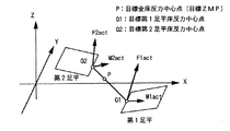
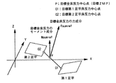
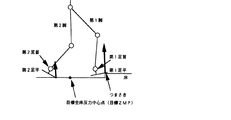
その複合コンプライアンス動作決定部の作業について説明する。説明の便宜のため、両脚支持期において図11に示すように第1足平22R(L)と第2足平22L(R)に実各足平床反力が作用している状況と仮定する。
The operation of the composite compliance operation determination unit will be described. For convenience of explanation, it is assumed that the actual foot floor reaction force is acting on the
ここでベクトルFnactは第n足平床反力の力成分を表す。ベクトルMnactは第n足平床反力のモーメント成分を表す。ベクトルMnactの向きは、向きに対して時計回りのモーメントが床から足平に作用していることを表す。 Here, the vector Fnact represents the force component of the nth foot floor reaction force. Vector Mact represents the moment component of the nth foot floor reaction force. The direction of the vector Mact represents that a clockwise moment acts on the foot from the floor with respect to the direction.
この瞬間の目標全床反力は、図12に示すようになっていると仮定する。ちなみに、目標全床反力中心点(目標ZMP)における目標全床反力モーメントベクトルMsumrefは垂直である(定義により、目標ZMPは目標全床反力モーメントの水平方向成分が0である点であるから)。 It is assumed that the desired total floor reaction force at this moment is as shown in FIG. Incidentally, the target total floor reaction force moment vector Msumref at the target total floor reaction force central point (target ZMP) is vertical (by definition, the target ZMP is a point where the horizontal component of the target total floor reaction force moment is zero. From).
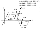
これを式1に従って目標各足平床反力に分配すると、図13に示すようになる。同図において、ベクトルFnrefは目標第n足平床反力の力成分を表す。ベクトルMnrefは目標第n足平床反力のモーメント成分を表す。ベクトルMnrefの向きの表現は、Mnactと同様である。
When this is distributed to each desired foot floor reaction force according to
説明のため、上体姿勢が左後ろに倒れそうな状態を想定する。 For the sake of explanation, it is assumed that the upper body posture is likely to fall back left.
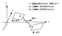
前述の姿勢安定化制御演算部では、ロボット1の上体傾斜偏差検出値θerrx,θerryに基づいて補償全床反力モーメントMdmdを算出する。この実施例では鉛直軸(Z軸)まわりのスピンを制御しないので、補償全床反力モーメントMdmdの鉛直軸成分は0である。上体位置の揺れも制御しないので、補償全床反力モーメントの力成分も0である。この状態に対応する補償全床反力モーメントMdmdを図14に示す。
In the above-described posture stabilization control calculation unit, the compensated total floor reaction force moment Mdmd is calculated based on the detected body tilt deviation values θerrx and θerror of the
姿勢を復元させるためには、目標全床反力中心点(目標ZMP)まわりの実全床反力モーメントの水平成分を、目標全床反力モーメントMsumrefと補償全床反力モーメントMdmdの和の水平成分に追従させれば良い。 In order to restore the posture, the horizontal component of the actual total floor reaction force moment around the target total floor reaction force central point (target ZMP) is obtained by adding the sum of the target total floor reaction force moment Msumref and the compensated total floor reaction force moment Mdmd. What is necessary is just to make it follow a horizontal component.
一方、目標全床反力中心点(目標ZMP)では目標全床反力モーメントMsumrefの水平方向成分は0である。従って、前後左右の姿勢傾きを復元させるためには、目標ZMPまわりの実全床反力モーメントの水平成分を、Mdmdの水平成分に追従させれば良い。 On the other hand, at the target total floor reaction force central point (target ZMP), the horizontal component of the target total floor reaction force moment Msumref is zero. Accordingly, in order to restore the posture inclination of the front, rear, left and right, the horizontal component of the actual total floor reaction force moment around the target ZMP may be made to follow the horizontal component of Mdmd.
この実施例にあっては複合コンプライアンス動作決定部は、以下の要求をできる限り満足するように足平の位置・姿勢を修正する。
要求1)ロボットの姿勢傾斜を安定化制御するために、目標全床反力中心点(目標ZMP)まわりの実全床反力モーメントの水平方向(X,Y軸方向)成分を、補償全床反力モーメントMdmdの水平方向成分に追従させる。
要求2)各足平の接地性を確保するために、できるかぎり目標各足平床反力中心点まわりの実各足平床反力モーメントの絶対値を小さくする。
In this embodiment, the composite compliance operation determining unit corrects the position / posture of the foot so as to satisfy the following requirements as much as possible.
Requirement 1) In order to stabilize and control the posture inclination of the robot, the horizontal direction (X, Y axis direction) component of the actual total floor reaction force moment around the target total floor reaction force center point (target ZMP) is The horizontal component of the reaction force moment Mdmd is made to follow.
Requirement 2) In order to secure the contact property of each foot, the absolute value of the actual foot floor reaction force moment around the desired foot floor reaction force center point is made as small as possible.
但し、前述の通り、要求1)と要求2)は、完全に両立させることはできず、ある点で妥協しなくてはならない。 However, as described above, request 1) and request 2) cannot be made completely compatible, and must be compromised at a certain point.
足平の位置・姿勢の修正は、この実施例では次のように行う。
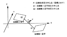
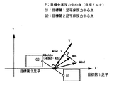
1)目標第1足平床反力中心点Q1と目標第2足平床反力中心点Q2を含み、かつ水平面と垂直な平面の法線ベクトルVを求める。Vの大きさは1とする。Vを図15に示す。
In this embodiment, the foot position / posture is corrected as follows.
1) A normal vector V of a plane including the target first foot floor reaction force center point Q1 and the target second foot floor reaction force center point Q2 and perpendicular to the horizontal plane is obtained. The magnitude of V is 1. V is shown in FIG.
2)目標第1足平床反力中心点Q1の座標を、目標全床反力中心点(目標ZMP)を回転中心に法線ベクトルVまわりに、ある回転角θdbvだけ回転移動する。移動した後の点をQ1’とする。同様に、目標第2足平床反力中心点Q2の座標を、目標全床反力中心点(目標ZMP)を回転中心に法線ベクトルVまわりに回転角θdbvだけ回転移動する。移動した後の点をQ2’とする。 2) The coordinates of the target first foot floor reaction force center point Q1 are rotated by a certain rotation angle θdbv around the normal vector V around the target total floor reaction force center point (target ZMP). Let Q1 'be the point after the movement. Similarly, the coordinates of the target second foot floor reaction force center point Q2 are rotated by the rotation angle θdbv around the normal vector V around the target total floor reaction force center point (target ZMP). Let Q2 'be the point after the movement.
この回転角θdbvを両脚補償角という。始点がQ1、終点がQ1’のベクトルをベクトルQ1Q1’とする。同様に、始点がQ2、終点がQ2’のベクトルをベクトルQ2Q2’とする。図16にQ1’とQ2’を示す。 This rotation angle θdbv is referred to as a both-leg compensation angle. A vector having a start point Q1 and an end point Q1 'is defined as a vector Q1Q1'. Similarly, a vector having a start point Q2 and an end point Q2 'is a vector Q2Q2'. FIG. 16 shows Q1 'and Q2'.
3)目標第1足平を、姿勢は変えずにベクトルQ1Q1’だけ平行移動(ほぼ上下移動)させる。同様に、目標第2足平を、姿勢は変えずにベクトルQ2Q2’だけ平行移動させる。移動後の目標各足平を図16に太線で示す。 3) The target first foot is translated (substantially moved up and down) by the vector Q1Q1 'without changing the posture. Similarly, the target second foot is translated by the vector Q2Q2 'without changing the posture. Each foot of the target after movement is indicated by a thick line in FIG.
4)次に、目標第1足平をQ1’を中心に、前後方向軸(X軸)まわりに回転角θ1x、左右方向軸(Y軸)まわりに回転角θ1yだけ回転させる。同様に、目標第2足平を目標第2足平をQ2’を中心に前後方向軸(X軸)まわりに回転角θ2x、左右方向軸(Y軸)まわりに回転角θ2yだけ回転させる。回転角θnx,θnyをそれぞれ第n足平X補償角、第n足平Y補償角という。回転後の目標各足平を図17に太線で示す。 4) Next, the target first foot is rotated about Q1 'by the rotation angle θ1x about the front-rear direction axis (X-axis) and by the rotation angle θ1y about the left-right direction axis (Y-axis). Similarly, the target second foot is rotated by the rotation angle θ2x about the front-rear direction axis (X axis) and the rotation angle θ2y about the left-right direction axis (Y axis) about Q2 ′. The rotation angles θnx and θny are referred to as the nth foot X compensation angle and the nth foot Y compensation angle, respectively. Each target foot after rotation is indicated by a bold line in FIG.
以上の補償動作量が過大でなければ、接地圧力分布は変わっても、接地領域(足底面の圧力が正の領域)は変わらない。このような場合には、補償動作量に比例して各足平に装着されたばね機構32や足底弾性体34などが変形し、変形量に応じた実各足平床反力が発生する。この結果、補償動作量と補償動作によって発生する実床反力の変化量との間の関係は、以下に示す良好な特性を持つ。
If the above compensation operation amount is not excessive, even if the ground pressure distribution changes, the ground contact area (area where the pressure on the sole surface is positive) does not change. In such a case, the
特性1)両脚補償角θdbvだけを操作して目標各足平位置を移動させると、下がった足平の実足平床反力の力成分が増加し、上がった足平の実足平床反力の力成分が減少する。このとき、修正目標各足平床反力中心点まわりの実各足平床反力モーメントは、ほとんど変化しない。 Characteristic 1) When only the leg compensation angle θdbv is operated to move the target foot position, the force component of the actual foot floor reaction force of the lowered foot increases, and the actual foot floor reaction force of the raised foot increases. The force component is reduced. At this time, the actual foot floor reaction force moments around the corrected desired foot floor reaction force center point hardly change.
特性2)第n足平X補償角だけを操作して目標第n足平姿勢を回転させると、目標第n足平床反力中心点に作用する実第n足平床反力のモーメントのX成分だけが変化し、その他の床反力成分は少ししか変化しない。同様に、第n足平Y補償角だけを操作して目標第n足平姿勢を回転させると、実第n足平床反力のモーメントのY成分だけが変化し、その他の床反力成分は少ししか変化しない。 Characteristic 2) When only the nth foot X compensation angle is operated to rotate the target nth foot posture, the X component of the moment of the actual nth foot floor reaction force acting on the target nth foot floor reaction force center point Only changes, and other floor reaction force components change little. Similarly, when only the nth foot Y compensation angle is operated to rotate the target nth foot posture, only the Y component of the moment of the actual nth foot floor reaction force changes, and the other floor reaction force components are It changes only a little.
特性3)両脚補償角θdbv、各足平X補償角および各足平Y補償角を同時に操作すると、実各足平床反力の変化量は、それぞれを単独に操作したときの変化量の和になる。 Characteristic 3) When the both leg compensation angle θdbv, each foot X compensation angle and each foot Y compensation angle are operated simultaneously, the change amount of the actual foot floor reaction force is the sum of the change amount when each of them is operated independently. Become.
特性1および特性2は、これらの操作に独立性があることを示し、特性3はこれらの操作に線形性があることを示していると言える。 Characteristic 1 and characteristic 2 indicate that these operations are independent, and it can be said that characteristic 3 indicates that these operations are linear.
図18は複合コンプライアンス動作決定部の演算処理を示すブロック図であり、同図を参照してこの作業を説明する。 FIG. 18 is a block diagram showing the calculation processing of the composite compliance operation determining unit, and this work will be described with reference to FIG.
概説すると、補償全床反力モーメント分配器において補償全床反力モーメントMdmdの分配を行う。次に、実各足平床反力と分配された補償全床反力モーメントなどから、両脚補償角決定部および第n足平X(Y)補償角決定部において前述の補償角θdbvおよびθnx(y)を決定する。 Briefly, the compensation total floor reaction force moment distributor distributes the compensation total floor reaction force moment Mdmd. Next, from the actual foot floor reaction force and the distributed total floor reaction force moment, etc., the above-described compensation angles θdbv and θnx (y ).
次に、決定された各種補償角に基づいて修正目標足平位置算出部は、補償された足平位置・姿勢(これを修正目標足平位置・姿勢という)を幾何学演算によって求める。最後に、機構変形補償入り修正目標足平位置・姿勢算出部は、目標各足平床反力によって発生が予想されるばね機構32や足底弾性体34の変形量を求め、それらを打ち消すように修正目標足平位置・姿勢をさらに修正する。
Next, the corrected desired foot position calculation unit obtains the compensated foot position / posture (referred to as the corrected target foot position / posture) by geometric calculation based on the determined various compensation angles. Finally, the corrected desired foot position / posture calculation unit with mechanism deformation compensation calculates the deformation amount of the
以下詳説すると、補償全床反力モーメント分配器は、補償全床反力モーメントMdmdを、両脚補償モーメントMdmddb、各足平補償モーメントMdmd1x,y,Mdmd2x,yに分配する。両脚補償モーメントMdmddbは、両脚補償角(足平上下量)θdbvを操作することによって目標全床反力中心点(目標ZMP)まわりに各足平床反力の力成分が作るモーメントの目標値である。 More specifically, the compensating total floor reaction force moment distributor distributes the compensating total floor reaction force moment Mdmd to both leg compensation moments Mdmddb and each foot compensation moment Mdmd1x, y, Mdmd2x, y. The both-leg compensation moment Mdmdb is a target value of a moment generated by the force component of each foot floor reaction force around the target total floor reaction force center point (target ZMP) by manipulating the both leg compensation angle (foot vertical amount) θdbv. .
両脚補償モーメントMdmddbのV方向まわりの成分をMdmddbvと記述する。尚、ベクトルVは複合コンプライアンス動作決定部の説明で定義したベクトルである。Vに直交し、鉛直方向にも直交するベクトルをUとすると、両脚補償モーメントMdmddbのU方向成分Mdmddbuは0に設定される。両脚補償角θdbvを操作しても、床反力のU方向モーメント成分を発生することはできないからである。 A component around the V direction of the both-leg compensation moment Mdmdb is described as Mdmddvv. The vector V is a vector defined in the description of the composite compliance operation determination unit. If a vector orthogonal to V and orthogonal to the vertical direction is U, the U-direction component Mdmddbu of the both-leg compensation moment Mdmddbu is set to zero. This is because the U-direction moment component of the floor reaction force cannot be generated even when the both-leg compensation angle θdbv is manipulated.
この実施例では補償全床反力モーメントMdmdの鉛直方向成分が0なので、Mdmddbの鉛直方向成分Mdmddbzも0に設定される。 In this embodiment, since the vertical component of the compensated total floor reaction force moment Mdmd is zero, the vertical component Mdmdbz of Mdmdb is also set to zero.
第1足平補償モーメントMdmd1は、第1足平補償角θ1x,θ1yを操作することによって目標第1足平床反力中心点まわりに発生させたいモーメントである。第1足平補償モーメントMdmd1のX成分をMdmd1x、Y成分をMdmdlyと記述する。第2足平補償モーメントMdmd2は、第2足平補償角θ2x,θ2yを操作することによって目標第2足平床反力中心点まわりに発生させたいモーメントである。第2足平補償モーメントMdmd2のX成分をMdmd2x、Y成分をMdmd2yと記述する。 The first foot compensation moment Mdmd1 is a moment that is desired to be generated around the target first foot floor reaction force center point by manipulating the first foot compensation angles θ1x and θ1y. The X component of the first foot compensation moment Mdmd1 is described as Mdmd1x, and the Y component is described as Mdmdly. The second foot compensation moment Mdmd2 is a moment that is desired to be generated around the desired second foot floor reaction force center point by manipulating the second foot compensation angles θ2x and θ2y. The X component of the second foot compensation moment Mdmd2 is described as Mdmd2x, and the Y component is described as Mdmd2y.
分配は、例えば次のように行う。
Mdmddbv = Wdbx * Mdmdx + Wdby * Mdmdy
・・・式3
Mdmd1x = W1x * (Mdmdx - Wint * Vx * Mdmddbv)
Mdmd1y = W1y * (Mdmdy - Wint * Vy * Mdmddbv)
Mdmd2x = W2x * (Mdmdx - Wint * Vx * Mdmddbv)
Mdmd2y = W2y * (Mdmdy - Wint * Vy * Mdmddbv)
・・・式4
The distribution is performed as follows, for example.
Mdmddbv = Wdbx * Mdmdx + Wdby * Mdmdy
...
Mdmd1x = W1x * (Mdmdx-Wint * Vx * Mdmddbv)
Mdmd1y = W1y * (Mdmdy-Wint * Vy * Mdmddbv)
Mdmd2x = W2x * (Mdmdx-Wint * Vx * Mdmddbv)
Mdmd2y = W2y * (Mdmdy-Wint * Vy * Mdmddbv)
...
ここで、Wdbx,Wdby,W1x,W1y,W2x,W2yおよびWintは分配用重み変数である。VxはベクトルVのX成分の値、VyはベクトルVのY成分の値である。この中で、Wintは、両脚補償角を操作することによって発生した全床反力モーメントを各足平補償角を操作することによって打ち消すためのものである。 Here, Wdbx, Wdby, W1x, W1y, W2x, W2y, and Wint are distribution weight variables. Vx is the value of the X component of the vector V, and Vy is the value of the Y component of the vector V. Among these, Wint is for canceling out the total floor reaction force moment generated by manipulating both leg compensation angles by manipulating each foot compensation angle.
式3と式4の演算処理を行う補償全床反力モーメント分配器のブロック図を図19に示す。
FIG. 19 shows a block diagram of a compensating total floor reaction force moment distributor that performs the arithmetic processing of
歩行時の分配用重み変数Wdbx,Wdby,W1x,W1y,W2x,W2yおよびWintの設定例を図20に示す。図20のパターンは、以下の注意点を考慮して決定することが望ましい。 FIG. 20 shows a setting example of distribution weight variables Wdbx, Wdby, W1x, W1y, W2x, W2y and Wint during walking. The pattern shown in FIG. 20 is desirably determined in consideration of the following points.
注意点1)両脚補償角と各足平補償角が不連続的に変化すると、関節に過大なトルクが発生する。そこで、両脚補償角と各足平補償角を連続的に変化させるために、分配用重み変数は連続的に変化させる。 Note 1) When both leg compensation angles and each foot compensation angle change discontinuously, excessive torque is generated at the joint. Therefore, the distribution weight variable is continuously changed in order to continuously change both leg compensation angles and each foot compensation angle.
注意点2)両脚補償角および各足平補償角を操作することによって発生する実床反力モーメントが、なるべく補償全床反力モーメントMdmdに近い値になるように、分配用重み変数を決定する。 Note 2) The distribution weight variable is determined so that the actual floor reaction force moment generated by manipulating both leg compensation angles and each foot compensation angle is as close to the compensated total floor reaction force moment Mdmd as possible. .
この際、直立時や歩行時など状況に応じて以下に示すように設定方針を変えた方が良い。直立時などのように、両脚補償モーメントのV方向成分Mdmddbv、各足平補償モーメントMdmd1,Mdmd2を忠実に実各足平床反力に発生させることができる状況では以下のように設定する。 At this time, it is better to change the setting policy as shown below according to the situation such as standing upright or walking. In a situation where the V-direction component Mdmdbv of the both leg compensation moments and the respective foot compensation moments Mdmd1 and Mdmd2 can be faithfully generated in each actual foot floor reaction force, such as when standing upright, the following settings are made.
この状況では目標全床反力中心点(目標ZMP)まわりの実全床反力モーメントの水平方向成分を、補償全床反力モーメントMdmdの水平方向成分に一致させるために、(即ち、前述の複合コンプライアンス動作決定部に対する要求1を満足するために、)式5と式6の両方をなるべく満足するように重みを設定すべきである。
In this situation, in order to make the horizontal component of the actual total floor reaction force moment around the target total floor reaction force center point (target ZMP) coincide with the horizontal component of the compensated total floor reaction force moment Mdmd (that is, as described above). In order to satisfy the
Mdmddbv*Vx + Mdmd1x + Mdmd2x = Mdmdx
・・・式5
Mdmddbv*Vy + Mdmd1y + Mdmd2y = Mdmdy
・・・式6
Mdmddbv * Vx + Mdmd1x + Mdmd2x = Mdmdx
... Formula 5
Mdmddbv * Vy + Mdmd1y + Mdmd2y = Mdmdy
... Formula 6
これに式3、式4を代入すると、式5は式7に、式6は式8に変換される。
(Wdbx * Mdmdx + Wdby * Mdmdy)*Vx + W1x * (Mdmdx - Wint * Vx * (Wdbx *
Mdmdx + Wdby * Mdmdy)) + W2x * (Mdmdx - Wint * Vx * (Wdbx * Mdmdx +
Wdby * Mdmdy))= Mdmdx
・・・式7
(Wdbx * Mdmdx + Wdby * Mdmdy)*Vy + W1y * (Mdmdy - Wint * Vy * (Wdbx *
Mdmdx + Wdby * Mdmdy)) + W2y * (Mdmdy - Wint * Vy * (Wdbx * Mdmdx +
Wdby * Mdmdy)) = Mdmdy
・・・式8
If
(Wdbx * Mdmdx + Wdby * Mdmdy) * Vx + W1x * (Mdmdx-Wint * Vx * (Wdbx *
Mdmdx + Wdby * Mdmdy)) + W2x * (Mdmdx-Wint * Vx * (Wdbx * Mdmdx +
Wdby * Mdmdy)) = Mdmdx
... Formula 7
(Wdbx * Mdmdx + Wdby * Mdmdy) * Vy + W1y * (Mdmdy-Wint * Vy * (Wdbx *
Mdmdx + Wdby * Mdmdy)) + W2y * (Mdmdy-Wint * Vy * (Wdbx * Mdmdx +
Wdby * Mdmdy)) = Mdmdy
...
MdmdxとMdmdyが任意の値を取っても、式7と式8が恒等的に成立するためには、式9、式10、および式11を同時に満足すれば良い。
Wint = 1 ・・・式9
W1x + W2x =1 ・・・式10
W1y + W2y =1 ・・・式11
即ち、以上の状況では式9、式10および式11を同時に満足するように、重みを決定すれば良い。
Even if Mdmdx and Mdmdy take arbitrary values,
Wint = 1 ・ ・ ・ Equation 9
W1x + W2x = 1 ・ ・ ・
W1y + W2y = 1 ・ ・ ・
That is, in the above situation, the weight may be determined so as to satisfy the
歩行時ではMdmddbvを目標にして両脚補償角θdbvを操作して足平の位置を修正しても、実全床反力モーメントの発生量がMdmddbvに較べて不足する場合がある。例えば図21のように両脚支持期の初期にロボットが後傾して第1足平が未だ着地していない状況では、θdbvによって第1足平の位置を下げても、実床反力は変化しない。 When walking, even if the position of the foot is corrected by manipulating both leg compensation angle θdbv with Mdmddbv as a target, the amount of actual floor reaction force moment generated may be insufficient compared to Mdmddv. For example, as shown in FIG. 21, in a situation where the robot tilts backward in the early stage of both-leg support and the first foot has not yet landed, the actual floor reaction force changes even if the position of the first foot is lowered by θdbv. do not do.
同様に、Mdmd2を目標にして第2足平補償角θ2を操作して第2足平の角度を修正しても、実床反力モーメントの増加量がMdmd2に較べて不足する場合がある。例えば、図22のように両脚支持期の後半にロボットが後傾している状況では、θ2によって第2足平のかかとを下げても実床反力は変化しない。 Similarly, even if the second foot angle is corrected by operating the second foot compensation angle θ2 with Mdmd2 as a target, the increase amount of the actual floor reaction force moment may be insufficient as compared with Mdmd2. For example, in the situation where the robot is tilted backward in the latter half of the both-leg support period as shown in FIG. 22, even if the heel of the second foot is lowered by θ2, the actual floor reaction force does not change.
従って、式5、式6を満足するように各重みを設定しても、複合コンプライアンス制御によって発生する実全床反力の増加量が補償全床反力モーメントMdmdに届かない場合がある。このようなことが生じる可能性が高い状況では、式5、式6の左辺の値を1より大きくすべきである。 Therefore, even if the respective weights are set so as to satisfy the expressions 5 and 6, the increase amount of the actual total floor reaction force generated by the composite compliance control may not reach the compensated total floor reaction force moment Mdmd. In situations where this is likely to occur, the value on the left side of Equations 5 and 6 should be greater than 1.
歩行時の分配用重み変数設定例である図20では、Wintを0に設定することによって、図21の状況のように、両脚補償角θdbv を操作しても実全床反力モーメントが発生できなくなっても、各足平補償角を操作して不足分を補うようにした。 In FIG. 20, which is an example of setting the distribution weight variable at the time of walking, by setting Wint to 0, an actual total floor reaction force moment can be generated even if the both-leg compensation angle θdbv is operated as in the situation of FIG. Even if it disappeared, each foot compensation angle was manipulated to compensate for the shortage.
好都合なことに、図21のように後傾すると第2足平のかかとが結果的に下がって床に接地しやすくなるので、第2足平補償角を操作することによって実全床反力モーメントを発生させることができるようになる。 Conveniently, as shown in FIG. 21, if the heel of the second foot is lowered as a result, the heel of the second foot tends to come into contact with the floor, so that the actual total floor reaction force moment can be obtained by manipulating the second foot compensation angle. Can be generated.
また、後傾していないときには両脚補償角θdbvを操作することによる実全床反力モーメントが発生するが、第2足平のかかとが床に接地しないので、第2足平補償角を操作しても実全床反力モーメントは発生しない。 In addition, an actual total floor reaction force moment is generated by manipulating the both-leg compensation angle θdbv when the vehicle is not tilted backward, but the heel of the second foot does not touch the floor, so the second foot compensation angle is manipulated. However, the actual total floor reaction force moment does not occur.
つまり、両脚補償角θdbvが有効に働くときには各足平補償角が有効に働かず、各足平補償角が有効に働くときには両脚補償角θdbvが有効に働かないので、結果的に両脚補償角および各足平補償角を操作することによって発生する実床反力モーメントの総量は、ほぼ補償全床反力モーメントMdmdに等しくなる。 That is, when the both leg compensation angle θdbv works effectively, each foot compensation angle does not work effectively, and when each foot compensation angle works effectively, the both leg compensation angle θdbv does not work effectively. The total amount of the actual floor reaction force moment generated by manipulating each foot compensation angle is substantially equal to the compensation total floor reaction force moment Mdmd.
状況によっては、両脚補償角および各足平補償角を操作することによって発生する実床反力モーメントの総量が補償全床反力モーメントMdmdよりも大きくなってしまう場合がある。 Depending on the situation, the total amount of actual floor reaction force moment generated by manipulating both leg compensation angles and each foot compensation angle may be larger than the compensation total floor reaction force moment Mdmd.
しかし、この場合でも、Mdmdがこの実施例のように姿勢安定化のためのフィードバック操作量であるならば、あまり問題にならない。何故ならば、Mdmdの大きさが多少違っていても、一般的に制御系に言えることであるが、制御系のオープンループゲインが多少変化するだけで、クローズドループ特性はほとんど変わらないからである。 However, even in this case, if Mdmd is a feedback manipulated variable for posture stabilization as in this embodiment, there is not much problem. This is because even if the magnitude of Mdmd is slightly different, it can generally be said to the control system, but only the open loop gain of the control system changes slightly, and the closed loop characteristics hardly change. .
注意点3)片脚支持期では、両脚補償角用の分配用重み変数であるWdbx,Wdbyの絶対値を小さくする。片脚支持期では両脚補償角を変化させても、接地していない足平が無駄に上下するだけで、実各足平床反力は変化しないからである。 Note 3) In the one-leg support period, the absolute values of Wdbx and Wdby, which are distribution weight variables for both-leg compensation angles, are reduced. This is because in the one-leg support period, even if the compensation angle for both legs is changed, the foot that is not in contact with the foot only moves up and down unnecessarily, and the actual foot floor reaction force does not change.
注意点4)足平の接地性を確保するために、目標足平床反力の力成分が小さいときには、その足平の足平補償角のための分配用重み変数の絶対値を小さくする。特に、足平が床から遠く離れているときには、その足平の足平補償角を動かしても、その足平の実足平床反力は変化しないので、不要な動きをさせないためにも、その足平の足平補償角のための分配用重み変数の絶対値を小さくすべきである。 Note 4) When the force component of the desired foot floor reaction force is small in order to secure the ground contact property of the foot, the absolute value of the distribution weight variable for the foot compensation angle of the foot is made small. In particular, when the foot is far from the floor, even if the foot compensation angle of the foot is moved, the actual foot floor reaction force of the foot does not change. The absolute value of the distribution weight variable for the foot compensation angle of the foot should be reduced.
注意点5)両脚補償角を操作することによって制御できる実全床反力モーメントの方向と、各足平補償角を操作することによって制御できる実全床反力モーメントの方向は通常異なる。 Note 5) The direction of the actual total floor reaction force moment that can be controlled by manipulating both leg compensation angles is different from the direction of the actual total floor reaction force moment that can be controlled by manipulating each foot compensation angle.
例えば、両脚補償角θdbvを操作することによって発生する実全床反力モーメントの向きは必ずV方向であり、V方向に直交する成分を発生させることはできない。一方、各足平補償角を操作することによって発生できる実全床反力モーメントの向きは、足平の接地状況によって制約を受ける。 For example, the direction of the actual total floor reaction force moment generated by manipulating the both-leg compensation angle θdbv is always the V direction, and a component orthogonal to the V direction cannot be generated. On the other hand, the direction of the actual total floor reaction force moment that can be generated by manipulating each foot compensation angle is limited by the ground contact state of the foot.
例えば、つまさきのエッジだけまたはかかとのエッジだけが接地している場合には、エッジ線方向にモーメントを発生することはできない。両脚支持期では、この特性を考慮して、なるべく無駄なく両脚補償角および各足平補償角を操作する。 For example, when only the toe edge or only the heel edge is grounded, a moment cannot be generated in the edge line direction. In the both-leg support period, in consideration of this characteristic, the both-leg compensation angle and each foot compensation angle are operated without waste as much as possible.
例えば、両脚補償角を操作するための分配重みWdbx,Wdbyは次のように決定する。 For example, the distribution weights Wdbx and Wdby for operating both leg compensation angles are determined as follows.
X成分がWdbx、Y成分がWdby、Z成分が0のベクトルをWdbとすると、式3はベクトルWdbとMdmdの内積になっている。従って、MdmdをベクトルWdb方向成分とその直交成分に分解し、ベクトルWdb方向成分だけを抽出して、ベクトルWdbの大きさを乗じたものが、式3によって求められるMdmddbvであると言える。
Assuming that a vector having an X component of Wdbx, a Y component of Wdby, and a Z component of 0 is Wdb,
この場合のMdmddbvを図23に示す。これは、両脚補償角を操作することによって実全床反力モーメントのWdb方向成分を制御するフィードバック制御系を構成することを意味する。もし、Wdb方向がベクトルVと直交していたら、両脚補償角をいくら操作しても実全床反力モーメントのWdb方向成分は発生しないから、このフィードバック制御系はただ無駄に両脚補償角を操作するだけになる。 FIG. 23 shows Mdmddbv in this case. This means that a feedback control system is configured to control the Wdb direction component of the actual total floor reaction force moment by manipulating both leg compensation angles. If the Wdb direction is orthogonal to the vector V, no matter how much the both-leg compensation angle is manipulated, the Wdb-direction component of the actual total floor reaction force moment does not occur, so this feedback control system simply manipulates the both-leg compensation angle. Just do it.
従って、無駄な動きを減らした場合には、Wdb方向をベクトルV方向に一致させるか、またはなるべく近づけるべきである。また、補償全床反力モーメントMdmdのWdb方向成分を、各足平補償角に頼らずに両脚補償角を操作するだけで発生させたいならば、WdbとVの内積が1になるように設定する。一部を各足平補償角に頼らせたいならば、WdbとVの内積が1より小さくなるように設定する。 Therefore, when the useless movement is reduced, the Wdb direction should coincide with the vector V direction or be as close as possible. If the Wdb direction component of the compensation total floor reaction force moment Mdmd is generated only by operating both leg compensation angles without depending on each foot compensation angle, the inner product of Wdb and V is set to 1. To do. If it is desired to rely on each foot compensation angle for a part, the inner product of Wdb and V is set to be smaller than 1.
ところで、足平の横幅が狭い場合には、各足平補償角を操作することによって発生し得る実各足平床反力モーメントのX成分は小さくなる。この場合には、Wdbxを大きめに設定する。Wdb方向とベクトルV方向は一致しなくなり、両脚補償角の変動が増加するが、安定性が増す。 By the way, when the lateral width of the foot is narrow, the X component of the actual foot floor reaction force moment that can be generated by operating each foot compensation angle becomes smaller. In this case, Wdbx is set larger. The Wdb direction and the vector V direction do not coincide with each other, and the variation of the both-leg compensation angle increases, but the stability increases.
両脚補償角決定部について更に詳説すると、図24は両脚補償角決定部の演算処理のブロック図であり、両脚補償角θdbvは図示の如く演算される。 Further details of the both-leg compensation angle determination unit will be described below. FIG. 24 is a block diagram of the calculation process of the both-leg compensation angle determination unit, and the both-leg compensation angle θdbv is calculated as shown in the figure.
図24を参照して説明すると、目標第1足平床反力中心点Q1に作用するF1actと目標第2足平床反力中心点Q2に作用するF2actが、目標全床反力中心点Pのまわりに発生させるモーメントMf1f2actを、次式により求める。 Referring to FIG. 24, F1act acting on the target first foot floor reaction force center point Q1 and F2act acting on the target second foot floor reaction force center point Q2 are around the desired total floor reaction force center point P. The moment Mf1f2act to be generated is calculated by the following equation.
Mf1f2act = PQ1*F1act + PQ2*F2act ・・・式12
ここで、PQ1は始点がP、終点がQ1のベクトル、PQ2は始点がP、終点がQ2のベクトルである。
Mf1f2act = PQ1 * F1act + PQ2 * F2act ・ ・ ・
Here, PQ1 is a vector whose start point is P and end point is Q1, and PQ2 is a vector whose start point is P and end point is Q2.
また、式12の代わりに、次式を用いても実際上はほとんど問題がない。
Mf1f2act = PQ1*F1act + PQ2*F2act+ M1act+ M2act ・・・式12a
式12aは、目標全床反力中心点まわりに作用する実全床反力モーメントMnactを算出する式になっている。尚、式12は、目標全床反力中心点まわりに作用する実全床反力モーメントから、目標各足平床反力中心点まわりに作用する実各足平床反力モーメントを減じたものになっている。
Moreover, there is practically no problem even if the following equation is used instead of
Mf1f2act = PQ1 * F1act + PQ2 * F2act + M1act + M2act ・ ・ ・ Equation 12a
Expression 12a is an expression for calculating the actual total floor reaction force moment Mact acting around the target total floor reaction force center point.
次に、Mf1f2actのベクトルV方向成分Mf1f2actvを抽出する。これは、ベクトルの内積演算を用いた次式によって得られる。尚、ベクトルVは前述の動作説明において図15に示したVである。
Mf1f2actv = Mf1f2act・V ・・・式13
Next, the vector V direction component Mf1f2actv of Mf1f2act is extracted. This is obtained by the following equation using a vector inner product operation. The vector V is the V shown in FIG. 15 in the above description of the operation.
Mf1f2actv = Mf1f2act ·
次に、Mf1f2actvをローパスフィルタに通してMf1f2actvfiltを得る。 Next, Mf1f2actvfilter is obtained by passing Mf1f2actv through a low-pass filter.
次に、両脚補償モーメントV方向成分Mdmddbvを補償用フィルタに通し、それを、Mf1f2actvfiltから減じ、偏差モーメントV方向成分Mdiffvを得る。 Next, the both-leg compensation moment V-direction component Mdmddbv is passed through the compensation filter, and is subtracted from Mf1f2actvfilt to obtain the deviation moment V-direction component Mdiffv.
尚、補償用フィルタは、Mdmddbvから実全床反力モーメントまでの伝達関数の周波数応答特性を改善するものである。 The compensation filter improves the frequency response characteristic of the transfer function from Mdmddbv to the actual total floor reaction force moment.
次に、足平ばね機構などの変形による両脚補償モーメントV方向成分への影響を打ち消すための両脚機構変形補償角θffdbvを求める。これは、いわゆるフィードフォワード補償である。 Next, a both-leg mechanism deformation compensation angle θffdbv for canceling the influence of the deformation of the foot spring mechanism or the like on the both-leg compensation moment V direction component is obtained. This is so-called feedforward compensation.
具体的には、両脚補償モーメントV方向成分Mdmddbvと変形量との関係を表す機構コンプライアンスモデルを用い、目標第1足平床反力中心点Q1と目標第2足平床反力中心点Q2を結ぶ線分の変形角度を求め、それの極性を反転したものを両脚機構変形補償角θffdbvとすれば良い。 Specifically, a line connecting the target first foot floor reaction force center point Q1 and the target second foot floor reaction force center point Q2 using a mechanism compliance model representing the relationship between the both-leg compensation moment V-direction component Mdmddbv and the deformation amount. What is necessary is just to obtain | require the deformation angle of a minute, and what reverse | inverted the polarity is made into the both-legs mechanism deformation compensation angle (theta) ffdbv.
両脚機構変形補償角θffdbvは、近似的には次式により求めれば良い。
θffdbv =−α*Mdmddbv ・・・式14
ここでαは所定の定数である。
The both-leg mechanism deformation compensation angle θffdbv may be obtained approximately by the following equation.
θffdbv = −α *
Here, α is a predetermined constant.
最後に次式によって両脚補償角θdbvを得る。ここでKdbは制御ゲインであり、通常、これは正の値に設定する。
θdbv = Kdb * Mdiffv+θffdbv ・・・式15
Finally, the both-leg compensation angle θdbv is obtained by the following equation. Here, Kdb is a control gain, which is normally set to a positive value.
θdbv = Kdb * Mdiffv + θffdbv Equation 15
第n足平補償角決定部について説明すると、図25はその中の第1足平X補償角決定部の演算処理を示すブロック図であり、第1足平X補償角θ1xは図示の如く演算する。説明は省略するが、第1足平Y補償角θ1y、第2足平X補償角θ2x、第2足平Y補償角θ2yも同様に求める。ここでは第1足平X補償角θ1xを求めるアルゴリズムだけを説明する。 The n-th foot compensation angle determination unit will be described. FIG. 25 is a block diagram showing the calculation processing of the first foot X compensation angle determination unit therein, and the first foot X compensation angle θ1x is calculated as shown in the figure. To do. Although the description is omitted, the first foot Y compensation angle θ1y, the second foot X compensation angle θ2x, and the second foot Y compensation angle θ2y are similarly obtained. Here, only the algorithm for obtaining the first foot X compensation angle θ1x will be described.
第1足平床反力モーメントX成分M1actxをローパスフィルタに通してM1actfiltxを得る。第1足平補償モーメントX成分Mdmd1xを補償用フィルタに通し、それを、M1actfiltxから減じ、偏差モーメントMdiff1xを得る。両脚補償角決定と同様、補償用フィルタは、Mdmd1xから実全床反力までの伝達関数の周波数応答特性を改善するものである。 The first foot floor reaction force moment X component M1actx is passed through a low-pass filter to obtain M1actfiltx. The first foot compensation moment X component Mdmd1x is passed through a compensation filter and is subtracted from M1actfiltx to obtain a deviation moment Mdiff1x. Similar to the determination of the both-leg compensation angle, the compensation filter improves the frequency response characteristic of the transfer function from Mdmd1x to the actual total floor reaction force.
次に、両脚補償角決定と同様、足平ばね機構などの変形による第1足平補償モーメントX成分への影響を打ち消すための第1足平X機構変形補償角θff1xを求める。これは、いわゆるフィードフォワード補償である。 Next, the first foot X mechanism deformation compensation angle θff1x for canceling the influence on the first foot compensation moment X component due to the deformation of the foot spring mechanism or the like is obtained in the same manner as the both-leg compensation angle determination. This is so-called feedforward compensation.
具体的には、第1足平補償モーメントX方向成分Mdmd1xと変形量との関係を表す機構コンプライアンスモデルを用い、第1足平の変形角度を求め、それの極性を反転したものを第1足平X機構変形補償角θff1xとすれば良い。 Specifically, using a mechanism compliance model representing the relationship between the first foot compensation moment X-direction component Mdmd1x and the amount of deformation, the deformation angle of the first foot is obtained, and the polarity of the first foot is inverted. The flat X mechanism deformation compensation angle θff1x may be used.
第1足平X機構変形補償角θff1xは、近似的には次式により求めれば良い。
θff1x=−α1x*Mdmd1x ・・・式16
ここでα1xは所定の定数である。
The first foot X mechanism deformation compensation angle θff1x may be determined approximately by the following equation.
θff1x = −α1x
Here, α1x is a predetermined constant.
最後に次式によって第1足平X補償角θ1xを得る。ここでK1xは制御ゲインであり、通常、これも正の値に設定する。
θ1x = K1x * Mdiff1x+θff1x ・・・式17
尚、図示のブロック線図は、演算処理順序を変えるなどの等価変形をしても良い。
Finally, the first foot X compensation angle θ1x is obtained by the following equation. Here, K1x is a control gain, which is normally set to a positive value.
θ1x = K1x * Mdiff1x + θff1x Equation 17
It should be noted that the illustrated block diagram may be equivalently modified such as changing the processing order.
図18に戻って説明を続けると、修正目標足平位置・姿勢算出部は、両脚補償角θdbv、第1足平X補償角θ1x、第1足平Y補償角θ1y、第2足平X補償角θ2x、第2足平Y補償角θ2yに基づき、前述の複合コンプライアンス動作の足平位置・姿勢修正手法に従って目標足平位置・姿勢を修正し、修正目標足平位置・姿勢を得る。 Returning to FIG. 18 and continuing the description, the corrected target foot position / posture calculation unit performs both leg compensation angle θdbv, first foot X compensation angle θ1x, first foot Y compensation angle θ1y, and second foot X compensation. Based on the angle θ2x and the second foot Y compensation angle θ2y, the target foot position / posture is corrected according to the above-described method for correcting the foot position / posture of the composite compliance operation to obtain the corrected target foot position / posture.
機構変形量算出部は、目標各足平床反力によって発生が予想されるばね機構32や足底弾性体34の変形量を求める。
The mechanism deformation amount calculation unit obtains deformation amounts of the
機構変形補償入り修正目標足平位置・姿勢算出部は、算出された機構変形量を打ち消すように、修正目標足平位置・姿勢をさらに修正し、機構変形補償入り修正目標足平位置・姿勢を得る。 The corrected target foot position / posture calculation unit including mechanism deformation compensation further corrects the corrected target foot position / posture so as to cancel the calculated mechanism deformation amount, and the corrected target foot position / posture including mechanism deformation compensation is determined. obtain.
例えば、図26に示すような機構変形量が予想されるときには、機構変形補償入り修正目標足平位置・姿勢は、図27に実線で示す位置・姿勢に修正される。即ち、図27に示す機構変形補償後の足平が目標足平床反力を受けて変形したときの位置・姿勢が、図26に示す機構変形補償前の足平位置・姿勢に一致するように、機構変形補償入り修正目標足平位置・姿勢を算出する。 For example, when a mechanism deformation amount as shown in FIG. 26 is predicted, the corrected target foot position / posture with mechanism deformation compensation is corrected to the position / posture indicated by the solid line in FIG. That is, the position / posture when the foot after mechanism deformation compensation shown in FIG. 27 is deformed by receiving the desired foot floor reaction force matches the foot position / posture before mechanism deformation compensation shown in FIG. Then, the corrected target foot position / posture with mechanism deformation compensation is calculated.
機構変形補償は、ばね機構32や足底弾性体34の変形によって生じる実足平位置・姿勢のずれをフィードフォワード的に打ち消す制御であり、この制御がない場合に比較し、より一層、目標歩容に近い歩行を実現することができる。
The mechanism deformation compensation is a control that cancels out the deviation of the actual foot position / posture caused by the deformation of the
上記を前提として図10フロー・チャートの説明に戻ると、前記の如く、S34において上記した補償角を決定する。 Returning to the description of the flowchart of FIG. 10 based on the above, the compensation angle described above is determined in S34 as described above.
図28はその作業を示すサブルーチン・フロー・チャートである。 FIG. 28 is a subroutine flow chart showing the work.
同図を参照して説明すると、先ずS100において前記したベクトルVを求め、S102に進んで分配用重み変数を図20に示すように設定し、現在時刻tでのこれらの値を求める。続いてS104に進み、式3および式4によって補償全床反力モーメントMdmdを両脚補償モーメントMdmddbvと各足平補償モーメントMdmdnx(y)に分配し、S106に進んで既述の如く両脚補償角θdbvを求め、S108に進んで各足平補償角θnx(y)を求める。
Referring to FIG. 20, first, the vector V described above is obtained in S100, the process proceeds to S102, the distribution weight variable is set as shown in FIG. 20, and these values at the current time t are obtained. Subsequently, the process proceeds to S104, and the total floor reaction force moment Mdmd is distributed to the both leg compensation moments Mdmddbv and the respective foot compensation moments Mdmdnx (y) according to
次いで図10フロー・チャートのS36に進み、目標各足平床反力に基づいて機構変形補償量を算出し、S38に進んで目標足平位置・姿勢を補償角θdbv,θnx(y)に応じて修正し、更にこれを機構変形補償量に応じて修正し、機構変形補償入り修正目標足平位置・姿勢を得る。 Next, the process proceeds to S36 in the flowchart of FIG. 10 to calculate a mechanism deformation compensation amount based on each desired foot floor reaction force, and proceeds to S38 to determine the desired foot position / posture according to the compensation angles θdbv, θnx (y). Then, this is corrected according to the mechanism deformation compensation amount to obtain the corrected target foot position / posture with mechanism deformation compensation.
次いでS40に進み、上体位置・姿勢と機構変形補償入り修正足平位置・姿勢から関節変位指令(値)を算出し、S42に進んで実関節変位を算出された関節変位指令(値)にサーボ制御し、S44に進んで時刻をΔt更新し、S14に戻って上記の処理を繰り返す。 Next, the process proceeds to S40, a joint displacement command (value) is calculated from the body position / posture and the corrected foot position / posture with mechanism deformation compensation, and the process proceeds to S42 to calculate the actual joint displacement to the calculated joint displacement command (value). Servo control is performed, the process proceeds to S44, the time is updated by Δt, and the process returns to S14 to repeat the above processing.
この実施例は上記の如く構成したので、これによって、概括すれば、実全床反力の制御と実各足平床反力の制御が殆ど干渉しないようになり、それらを容易に制御することができる。 Since this embodiment is configured as described above, in summary, the control of the actual total floor reaction force and the control of the actual foot floor reaction force hardly interfere with each other and can be easily controlled. it can.
即ち、この実施例に係る装置は、先に提案した技術に対して以下の点を改良した。即ち、特開平5−305584号公報で提案した足首コンプライアンス制御では、足首または足底の基準点などの足平に固定された点における実床反力モーメントを検出し、それに基づいて前記固定されたを中心に足平を回転させていたが、この実施例に係る装置では、移動する目標足平床反力中心点における実各足平床反力モーメントを算出し、それに基づいて目標足平床反力中心点を中心に足平を回転させるように変更し、その点まわりのモーメントを望ましい値に制御するようにした。 That is, the apparatus according to this embodiment has the following improvements over the previously proposed technology. That is, in the ankle compliance control proposed in JP-A-5-305584, an actual floor reaction force moment at a point fixed to the foot such as the reference point of the ankle or the sole is detected, and the fixed force is detected based on the detected moment. In the apparatus according to this embodiment, the actual foot floor reaction force moment at the moving target foot floor reaction force center point is calculated, and the desired foot floor reaction force center is calculated based on the calculated foot floor reaction force moment. Changed to rotate the foot around the point, and controlled the moment around the point to the desired value.
この結果、実全床反力と実各足平床反力がほとんど干渉することなく、容易に制御することが可能となった。より干渉を少なくするために、各瞬間における想定していた足底接地領域内にもっと適切な点を選定しても良い。 As a result, the actual total floor reaction force and the actual foot floor reaction force can be easily controlled with little interference. In order to further reduce the interference, a more appropriate point may be selected within the assumed ground contact area at each moment.
更には、ロボットに作用する床反力、より具体的には目標全床反力中心点(目標ZMP)まわりの実全床反力モーメントと目標各足平中心点まわりの実各足平床反力モーメントを容易かつ適切に制御することができる。換言すれば、先に提案した両脚コンプライアンス制御および足首コンプライアンス制御の併用に比較して、制御の干渉がなく、実全床反力と実各足平床反力が望ましい値からずれたり発振することがない。 Furthermore, the floor reaction force acting on the robot, more specifically, the actual total floor reaction force moment about the target total floor reaction force center point (target ZMP) and the actual foot floor reaction force about each target foot center point. The moment can be easily and appropriately controlled. In other words, compared to the previously proposed combined use of both leg compliance control and ankle compliance control, there is no control interference, and the actual total floor reaction force and the actual foot floor reaction force may deviate or oscillate from desired values. Absent.
従って、大域的なうねりや傾斜だけでなく、局所的な凹凸や傾斜なども含む予期しない床形状変化があっても、その影響をあまり受けずに脚式移動ロボットに作用する床反力を適切に制御することができる。 Therefore, the floor reaction force acting on the legged mobile robot is not affected by unexpected changes in the floor shape, including not only global swell and inclination but also local unevenness and inclination. Can be controlled.
また、脚式移動ロボットの姿勢安定化制御を容易に実現できると共に、脚式移動ロボットが受ける着地衝撃を低減することができ、脚式移動ロボットの接地性を高め、歩行時のスリップやスピンを防止することができる。更に、脚式移動ロボットのアクチュエータの負荷を低減することができる。 In addition, the legged mobile robot's posture stabilization control can be easily realized, the landing impact received by the legged mobile robot can be reduced, the grounding performance of the legged mobile robot can be improved, and slip and spin during walking can be reduced. Can be prevented. Furthermore, the load on the actuator of the legged mobile robot can be reduced.
また、特開平5−305586号公報で提案した両脚コンプライアンス制御では実全床反力(各足平床反力の合力)の目標全床反力中心点(目標ZMP)まわりのモーメント成分を検出し、その値が望ましい値になるように制御していたが、この実施例に係る装置においては、目標各足平床反力中心点に作用する足平床反力の内のモーメント成分を除いた並進力成分の合成が目標全床反力中心点(目標ZMP)まわりに作用するモーメントを検出し、その値を望ましい値になるように制御するように変更した(尚、この点は先に提案した制御手法であっても良い)。 Further, in the both-leg compliance control proposed in JP-A-5-305586, the moment component around the target total floor reaction force center point (target ZMP) of the actual total floor reaction force (the resultant force of each floor floor reaction force) is detected, Although the value was controlled so as to be a desirable value, in the apparatus according to this embodiment, the translational force component excluding the moment component of the foot floor reaction force acting on each desired foot floor reaction force central point. Is detected so as to control the value to be a desired value (this point is the previously proposed control method) May be).
図29はこの発明に係る脚式移動ロボットの制御装置の第2の実施例を示す、図16と同様な説明図である。 FIG. 29 is an explanatory view similar to FIG. 16, showing a second embodiment of the control device for the legged mobile robot according to the present invention.
第2の実施例に係る装置は補償動作を簡易化した。この実施例においては、各足平の床反力の力成分を操作する足平位置修正動作の手法としては、図16に示した手法に代え、図29に示すように、鉛直方向にだけ移動させるようにした。このとき、第1足平鉛直方向移動量Z1と第2足平鉛直方向移動量Z2は、次式によって求める。
Z1 = -線分PQ1 の長さ *θdbv
Z2 = 線分PQ2 の長さ *θdbv
・・・式18
但し、ここで、θdbvには式15で求められる値を代入する。
The apparatus according to the second embodiment simplified the compensation operation. In this embodiment, the foot position correcting operation method for operating the force component of the floor reaction force of each foot is replaced with the method shown in FIG. 16 and moved only in the vertical direction as shown in FIG. I tried to make it. At this time, the first foot vertical movement amount Z1 and the second foot vertical movement amount Z2 are obtained by the following equations.
Z1 = -Length of line segment PQ1 * θdbv
Z2 = length of line segment PQ2 * θdbv
...
However, here, the value obtained by Equation 15 is substituted for θdbv.
尚、その他の構成は、第1の実施例と異ならない。第2の実施例においては、上記の如く構成したことで、第1の実施例とほぼ同様の作用、効果を得ることができる。 The other configuration is not different from the first embodiment. In the second embodiment, by configuring as described above, it is possible to obtain substantially the same operations and effects as in the first embodiment.
図30はこの発明に係る脚式移動ロボットの制御装置の第3の実施例を示す、図4と同様な説明図である。また、図31は、その動作を示す、図10と同様なフロー・チャートである。 FIG. 30 is an explanatory view similar to FIG. 4, showing a third embodiment of the control device for the legged mobile robot according to the present invention. FIG. 31 is a flowchart similar to FIG. 10 showing the operation.
第3の実施例においては、実全床反力モーメントのZ成分(鉛直軸まわり成分)に対するコンプライアンス制御を追加した。即ち、第3の実施例は、前記したZ軸まわり固有回転振動に起因する実各足平床反力モーメントのZ成分を低減するようにした。 In the third embodiment, compliance control for the Z component (the component around the vertical axis) of the actual total floor reaction force moment is added. That is, in the third embodiment, the Z component of the actual foot floor reaction force moment caused by the natural rotational vibration around the Z axis is reduced.
第3の実施例にあっては、そのために、第1の実施例に係る装置の構成に、状態検出器、姿勢安定化制御演算部、複合コンプライアンス動作決定部に新たな機能を追加した。 In the third embodiment, for this purpose, new functions are added to the configuration of the apparatus according to the first embodiment in the state detector, the posture stabilization control calculation unit, and the composite compliance operation determination unit.
図30を参照して説明すると、第3の実施例に係る装置においては先ず、ロボット1の上体24の適宜位置にヨーレートセンサ100を設けると共に、その出力などを入力し、現在の位置、姿勢、および進行方向を推定する自己位置・姿勢・方向推定器102を備えるようにした。ヨーレートセンサ100は、ロボット1のZ軸まわりのヨーレート(回転角速度)に応じた信号を出力する。尚、X,Y軸まわりの回転角速度は、傾斜センサ60の出力に基づいて算出する。
Referring to FIG. 30, in the apparatus according to the third embodiment, first, the yaw rate sensor 100 is provided at an appropriate position of the
自己位置・姿勢・方向推定器102は、目標足平軌道または実関節角に基づいて一歩前の着地位置に対する今回の着地位置の相対位置および方向を求めると共に、ヨーレートセンサ100の検出値を積分することにより、ロボットの進行方向を検出する。
The self-position / posture /
さらに、これらの情報に基づき、デッドレコニングによって、目標経路に対するロボット1の位置ずれと方向ずれを推定する。尚、デッドレコニングでは推定値の誤差が発散する傾向があるので、カメラなどを用いて環境を認識して補正しても良い。また、上体24が鉛直軸に対して傾くと、旋回時のヨーレート検出値は実際値より少ない値となるので、傾斜センサ60の出力によってヨーレート検出値を補正するのが望ましい。
Further, based on these pieces of information, the positional deviation and the direction deviation of the
第3の実施例に係る装置を図31フロー・チャートを参照して説明すると、S10からS30まで進んだ後、S30aにおいて、推定されたロボット1の位置および/または方向のずれに基づき、そのずれが減少するように、補償全床反力モーメントのZ成分Mdmdzを求める。
The apparatus according to the third embodiment will be described with reference to the flowchart of FIG. 31. After proceeding from S10 to S30, in S30a, based on the estimated position and / or direction deviation of the
以下、図32に示す経路に沿って歩行する場合を例にとって説明すると、上記した補償全床反力モーメントのZ成分Mdmdzを求める制御則として次式を用いる。
Mdmdz =−Kthzθerrz− Kwz (dθerrz / dt)− Khzh
・・・式19
ここで、θerrzは方向のずれ、dθerrz/dtはその時間微分値、hは経路からの横ずれである。同図にθerrz,hを示す。この図の状態では、θerrz,hは正である。また、Kthz,KwzおよびKhzは経路誘導制御ゲイン(定数)である。
Hereinafter, the case of walking along the route shown in FIG. 32 will be described as an example. The following equation is used as a control law for obtaining the Z component Mdmdz of the compensated total floor reaction force moment.
Mdmdz = −Kthzθerrz− Kwz (dθerrz / dt) − Khzh
... Formula 19
Here, θerrz is a deviation in direction, dθerrz / dt is a time differential value thereof, and h is a lateral deviation from the path. The figure shows θerrz, h. In the state of this figure, θerrz, h is positive. Kthz, Kwz, and Khz are route guidance control gains (constants).
前記した如く、ロボット1が歩行しているとき、足平のばね機構32や足底弾性体34のねじれ弾性とロボット1の鉛直軸まわりの慣性力モーメントによって、上体24が鉛直軸まわりに回転振動する。これをZ軸まわり固有回転振動と呼ぶ。この振動によって、実各足平床反力モーメントのZ成分が振動する。ロボット1が歩行しているとき、実足平床反力は、ほぼ、目標足平床反力モーメントと上記振動の和になる。
As described above, when the
上記振動の振幅が過大になると、実足平床反力モーメントのピーク値が摩擦の限界を超え、その瞬間に足底が滑り、ロボット1はスピンする。スピンが大きいと、姿勢安定性を失って転倒する場合もある。つまり、Z軸まわり固有回転振動を抑制するだけでも、姿勢安定性を向上させる効果があることがわかる。
When the amplitude of the vibration becomes excessive, the peak value of the actual foot floor reaction force moment exceeds the limit of friction, and at that moment, the sole slips and the
尚、単にZ軸まわり固有回転振動を抑制するだけならば、ヨーレートのずれ(方向ずれの時間微分値)だけから補償全床反力モーメントのZ成分Mdmdzを決定すれば良い。即ち、式19において、Kwz以外の経路誘導制御ゲインを0に設定すれば良い。 If the natural rotational vibration around the Z axis is merely suppressed, the Z component Mdmdz of the compensated total floor reaction force moment may be determined from only the yaw rate deviation (time differential value of the direction deviation). That is, in Equation 19, the route guidance control gain other than Kwz may be set to 0.
また、第3の実施例においては、複合コンプライアンス動作決定部に新たな機能を追加した。具体的には、実全床反力と実各足平床反力のZ軸まわりモーメント成分を操作するため、足平22R(L)の位置姿勢の修正動作を、第1の実施例での動作に加えた。複合コンプライアンス動作決定部は、この修正量を決定する。
In the third embodiment, a new function is added to the composite compliance operation determination unit. Specifically, in order to manipulate the moment component around the Z-axis of the actual total floor reaction force and the actual foot floor reaction force, the position / posture correction operation of the
その決定方法を述べる前に、追加される動作を以下に具体的に説明する。 Before describing the determination method, the added operation will be specifically described below.
全床反力と各足平床反力のZ軸まわりモーメント成分を操作するための足平の位置姿勢の修正は、第1の実施例で述べた複合コンプライアンス動作によって得られた、修正目標各足平位置姿勢(図16の太線の足平)と修正目標各足平床反力中心点(図16のQ1’,Q2’)に対して次のような修正を加えることによって行われる。 The correction of the position and posture of the foot for manipulating the moment component about the Z-axis of the total floor reaction force and the floor reaction force of each foot is performed by the composite compliance operation described in the first embodiment. This is done by applying the following correction to the flat position / posture (the thick foot in FIG. 16) and the corrected foot floor reaction force center points (Q1 ′, Q2 ′ in FIG. 16).
1)修正目標第1足平床反力中心点(図16のQ1’)の座標を、目標全床反力作用点(目標ZMP)を回転中心に、Z軸まわりに、ある回転角θdbzだけ回転移動(rotate)する。移動した後の点をQ1”とする。 1) The coordinates of the corrected target first foot floor reaction force center point (Q1 ′ in FIG. 16) are rotated by a rotation angle θdbz around the Z axis with the target total floor reaction force action point (target ZMP) as the rotation center. Rotate. Let Q1 "be the point after the movement.
同様に、目標第2足平床反力中心点(図16のQ2’)の座標を、目標全床反力作用点(目標ZMP)を回転中心に、Z軸まわりに、ある回転角θdbzだけ回転移動(rotate)する。移動した後の点をQ2”とする。この回転角θdbzを、Z軸まわり両脚補償角と呼ぶ。 Similarly, the coordinates of the target second foot floor reaction force central point (Q2 ′ in FIG. 16) are rotated by a rotation angle θdbz around the Z axis with the target total floor reaction force action point (target ZMP) as the rotation center. Rotate. The point after the movement is defined as Q2 ″. This rotation angle θdbz is called a both-leg compensation angle around the Z axis.
2)始点がQ1’終点がQ1”のベクトルをベクトルQ1’Q1”とする。同様に、始点がQ2’終点がQ2”のベクトルをベクトルQ2’Q2”とする。図33に上方から見たQ1”とQ2”を示す。 2) A vector having a start point Q1 'and an end point Q1 "is defined as a vector Q1'Q1". Similarly, a vector having a start point Q2 'and an end point Q2 "is set as a vector Q2'Q2". FIG. 33 shows Q1 ″ and Q2 ″ viewed from above.
3)修正目標第1足平を、姿勢は変えずに、ベクトルQ1’Q1”だけ平行移動させる。同様に、修正目標第2足平を、姿勢は変えずに、ベクトルQ2’Q2”だけ平行移動させる。移動後の修正目標各足平を図33に太線で示す。 3) The correction target first foot is translated by the vector Q1′Q1 ″ without changing the posture. Similarly, the correction target second foot is parallel by the vector Q2′Q2 ″ without changing the posture. Move. Each corrected target foot after movement is indicated by a bold line in FIG.
4)次に、3)で得られた修正目標第1足平をQ1”を中心に、鉛直方向軸(Z軸)まわりに回転角θ1zだけ回転させる。同様に、3)で得られた修正目標第2足平をQ2”を中心に、鉛直方向軸(Z軸)まわりに回転角θ2zだけ回転させる。回転角θnzを第n足平Z補償角と呼ぶ。回転後の修正目標各足平を図34に太線で示す。 4) Next, the correction target first foot obtained in 3) is rotated about the vertical axis (Z axis) by Q1 ″ around the rotation angle θ1z. Similarly, the correction obtained in 3) The target second foot is rotated about the vertical axis (Z-axis) by a rotation angle θ2z around Q2 ″. The rotation angle θnz is called the nth foot Z compensation angle. Each corrected target foot after rotation is indicated by a thick line in FIG.
以上の補償動作量が過大でなければ、補償動作量と補償動作によって発生する実床反力の変化量との間の関係は、以下に示す良好な特性を持つ。 If the above compensation operation amount is not excessive, the relationship between the compensation operation amount and the amount of change in the actual floor reaction force generated by the compensation operation has the following good characteristics.
特性1)Z軸まわり両脚補償角θdbzだけを操作して修正目標各足平位置を移動させると、移動向きと逆向きに実各足平床反力の力成分が発生する。このとき、修正目標各足平実床反力中心点まわりの実各足平床反力モーメントは、ほとんど変化しない。 Characteristic 1) When only the leg compensation angle θdbz around the Z axis is operated to move the corrected target foot position, a force component of the actual foot floor reaction force is generated in the direction opposite to the moving direction. At this time, the actual foot floor reaction force moment around the corrected target foot actual floor reaction force center point hardly changes.
特性2)第n足平Z補償角だけを操作して目標各足平姿勢を回転させると、目標第n足平床反力中心点に作用する実第n足平床反力のモーメントのZ軸成分だけが変化し、その他の床反力成分は少ししか変化しない。 Characteristic 2) When only the nth foot Z compensation angle is operated to rotate each desired foot posture, the Z-axis component of the moment of the actual nth foot floor reaction force acting on the target nth foot floor reaction force center point Only changes, and other floor reaction force components change little.
特性3)両脚補償角θdbz、各足平X補償角、各足平Y補償角、Z軸まわり両脚補償角θdbzおよび各足平Z補償角を同時に操作すると、実各足平床反力の変化量は、それぞれを単独に操作したときの変化量の和になる(換言すれば、線形結合が可能になる)。 Characteristic 3) When the both leg compensation angle θdbz, each foot X compensation angle, each foot Y compensation angle, both Z-leg both leg compensation angle θdbz and each foot Z compensation angle are operated simultaneously, the amount of change in the actual foot floor reaction force Is the sum of the amount of change when each is operated independently (in other words, linear combination is possible).
特性1および特性2は、これらの操作に独立性があることを示し、特性3は全ての操作に線形性があることを示していると言える。 Characteristic 1 and characteristic 2 indicate that these operations are independent, and it can be said that characteristic 3 indicates that all operations are linear.
以上の動作におけるZ軸まわり両脚補償角θdbzおよび各足平Z補償角を、複合コンプライアンス動作決定部において以下のように決定する。 The Z-axis both-legs compensation angle θdbz and each foot Z compensation angle in the above operation are determined in the composite compliance operation determination unit as follows.
図35に第3の実施例の複合コンプライアンス部の概要ブロック図を示す。図示の如く、モーメントZ成分補償動作決定部104を追加した。図36にそのモーメントZ成分補償動作決定部104の詳細を示す。以下、この追加部分を中心に説明する。 FIG. 35 shows a schematic block diagram of the composite compliance unit of the third embodiment. As shown in the figure, a moment Z component compensation operation determining unit 104 is added. FIG. 36 shows details of the moment Z component compensation operation determination unit 104. Hereinafter, this additional portion will be mainly described.
図36に示す如く、このZ成分補償モーメント決定部104においては、補償全床反力モーメント分配器の出力から、両脚補償モーメントMdmddbのZ成分Mdmdbzと各足平補償モーメントMdmd1z,Mdmd2zを決定すると共に、実各足平床反力と分配された補償モーメントZ成分(Mdmddbz,Mdmdnz)などから、Z軸まわり両脚補償角θdbz、第1足平Z補償角θ1zおよび第2足平Z補償角θ2zを決定する(これは図38フロー・チャートでS34aの処理に相当する)。 As shown in FIG. 36, the Z component compensation moment determination unit 104 determines the Z component Mdmdbz and the foot compensation moments Mdmd1z and Mdmd2z of both leg compensation moments Mdmdb from the output of the compensating total floor reaction force moment distributor. From the actual foot floor reaction force and the distributed compensation moment Z component (Mdmddbz, Mdmdnz), etc., both leg compensation angle θdbz around the Z axis, first foot Z compensation angle θ1z and second foot Z compensation angle θ2z are determined. (This corresponds to the process of S34a in the flowchart of FIG. 38).
修正目標足平位置姿勢算出部では、Z軸まわり両脚補償角および各足平Z補償角も含めて、修正足平位置姿勢を幾何学演算によって求める。 The corrected desired foot position / posture calculation unit obtains a corrected foot position / posture including geometric compensation by including both leg compensation angles around the Z axis and each foot Z compensation angle.
以下に追加処理の詳細を説明する。 Details of the additional processing will be described below.
図37を参照して補償全床反力モーメントの分配について説明すると、補償全床反力モーメント分配器では、補償全床反力モーメントMdmdのZ成分Mdmdzを、両脚補償モーメントMdmddbのZ成分Mdmddbz、第1足平補償モーメントMdmd1のZ成分Mdmd1z、第2足平補償モーメントMdmd2のZ成分Mdmd2z、に分配する処理が追加される。 The distribution of the compensated total floor reaction force moment will be described with reference to FIG. 37. In the compensated total floor reaction force moment distributor, the Z component Mdmddz of the compensation total floor reaction force moment Mdmd is changed to the Z component Mdmdbz of both legs compensation moment Mdmddb, A process of distributing to the Z component Mdmd1z of the first foot compensation moment Mdmd1 and the Z component Mdmd2z of the second foot compensation moment Mdmd2 is added.
尚、両脚補償モーメントのZ成分Mdmddbzは、両脚補償角θdbzを操作することによって目標全床反力中心点(目標ZMP)まわりに各足平床反力の力成分Fnactが作るモーメントのZ成分の目標値である。 Note that the Z component Mdmddbz of the both-leg compensation moment is the target of the Z component of the moment created by the force component Fnact of each foot floor reaction force around the desired total floor reaction force center point (target ZMP) by manipulating the both-leg compensation angle θdbz. Value.
また、第1足平補償モーメントのZ成分Mdmd1zは、第1足平補償角θ1zを操作することによって目標第1足平床反力中心点まわりに発生させたいモーメントZ成分(図34にM1で示す)である。同様に、第2足平補償モーメントのZ成分Mdmd2は、第2足平補償角θ2zを操作することによって目標第2足平床反力中心点まわりに発生させたいモーメントZ成分(図34にM2で示す)である。 Further, the Z component Mdmd1z of the first foot compensation moment is the moment Z component (indicated by M1 in FIG. 34) that is desired to be generated around the desired first foot floor reaction force center point by manipulating the first foot compensation angle θ1z. ). Similarly, the Z component Mdmd2 of the second foot compensation moment is the moment Z component (M2 in FIG. 34) that is desired to be generated around the target second foot floor reaction force center point by manipulating the second foot compensation angle θ2z. Show).
分配は、例えば、次式を用いて行う。
Mdmddbz =Wdbz× Mdmdz
Mdmd1z =W1z × Mdmdz
Mdmd2z =W2z × Mdmdz
・・・式20
ここで、Wdbz,W1z,W2zは歩行時の分配用重み変数である。その分配用重み変数Wdbz,W1z,W2zの設定例を、図38に示す。同図の設定パターンは、以下の注意点を考慮して決定される。
The distribution is performed using, for example, the following equation.
Mdmddbz = Wdbz x Mdmdz
Mdmd1z = W1z × Mdmdz
Mdmd2z = W2z × Mdmdz
... Formula 20
Here, Wdbz, W1z, and W2z are distribution weight variables during walking. An example of setting the distribution weight variables Wdbz, W1z, and W2z is shown in FIG. The setting pattern shown in the figure is determined in consideration of the following points.
注意点1)両脚補償角と各足平補償角が不連続的に変化すると、関節に過大なトルクが発生する。そこで、両脚補償角と各足平補償角を連続的に変化させるために、分配用重み変数は連続的に変化させる。 Note 1) When both leg compensation angles and each foot compensation angle change discontinuously, excessive torque is generated at the joint. Therefore, the distribution weight variable is continuously changed in order to continuously change both leg compensation angles and each foot compensation angle.
注意点2)Z軸まわり両脚補償角および各足平Z補償角を操作することによって発生する実床反力モーメントのZ成分が、なるべく補償全床反力モーメントのZ成分Mdmdzに近い値になるように、分配用重み変数Wdbz,W1z,W2zを決定する。 Note 2) The Z component of the actual floor reaction force moment generated by manipulating both leg compensation angles around the Z axis and each foot Z compensation angle is as close as possible to the Z component Mdmdz of the compensation total floor reaction force moment. Thus, the distribution weight variables Wdbz, W1z, and W2z are determined.
直立時などのように、両脚補償モーメントのZ成分Mdmddbz、各足平補償モーメントZ成分Mdmd1z,Mdmd2zを忠実に実各足平床反力に発生させることができる状況では、以下のように設定する。即ち、目標全床反力中心点(目標ZMP)まわりの実床反力モーメントMactのZ成分を、補償全床反力モーメントMdmdのZ成分に一致させる(換言すれば、第1の実施例で述べた複合コンプライアンス動作部に対する要求1を満足する)ために、以下の式21を可能な限り満足するように重みを設定する。
In a situation where the Z component Mdmddbz and the foot compensation moment Z components Mdmd1z and Mdmd2z of the both leg compensation moments can be faithfully generated in the actual foot floor reaction force, such as when standing upright, the following settings are made. That is, the Z component of the actual floor reaction force moment Mact around the target total floor reaction force center point (target ZMP) is made to coincide with the Z component of the compensated total floor reaction force moment Mdmd (in other words, in the first embodiment). In order to satisfy the
Wdbz+ W1z+ W2z= 1
・・・式21
尚、歩行時では、式21の左辺が1に近ければ十分である。換言すれば、必ずしも1でなくても良い。
Wdbz + W1z + W2z = 1
... Formula 21
When walking, it is sufficient if the left side of Equation 21 is close to 1. In other words, it does not necessarily have to be 1.
注意点3)遊脚足平が着地する時点でZ軸まわり両脚補償角θdbzが0でないと、足平着地位置が目標位置からずれ、軌道誘導制御に悪影響を及ぼす場合がある。従って、足平が着地する時点付近で、Z軸まわり両脚補償角用の分配用重み変数Wdbzを0にするのが望ましい。 Note 3) If the leg compensation angle θdbz around the Z-axis is not 0 when the free leg foot lands, the foot landing position may deviate from the target position, which may adversely affect the trajectory guidance control. Therefore, it is desirable to set the distribution weight variable Wdbz for the both-leg compensation angle around the Z axis to 0 near the time when the foot lands.
注意点4)遊脚足平が着地する時点でその足平のZ補償角が0でないと、足平着地向きが目標向きからずれ、軌道誘導制御に悪影響を及ばす場合がある。従って、第1足平が着地する時点付近で、第1足平Z補償角用の分配用重み変数W1zを0にし、第2足平が着地する頃では、第2足平Z補償角用の分配用重み変数W2zを0にするのが望ましい。 Note 4) If the Z-compensation angle of the free leg foot is not zero at the time of landing, the foot landing direction may deviate from the target direction, which may adversely affect the trajectory guidance control. Accordingly, the distribution weight variable W1z for the first foot Z compensation angle is set to 0 near the time when the first foot lands, and when the second foot lands, the second foot Z compensation angle It is desirable to set the distribution weight variable W2z to 0.
また、Z軸まわり両脚補償角θdbzの決定処理が追加される。Z軸まわり両脚補償角θdbzは、両脚補償角θdbvと同様のアルゴリズムによって求められる。違いは、モーメントと角度の向きがV方向からZ方向に変わっただけである。従って、Z軸まわり両脚補償角θdbzを決定する処理のブロック図は、図24のVをZに置き換えることによって得ることができる。 In addition, a process of determining both leg compensation angles θdbz around the Z axis is added. The both-leg compensation angle θdbz around the Z-axis is obtained by the same algorithm as the both-leg compensation angle θdbv. The only difference is that the direction of moment and angle has changed from V direction to Z direction. Therefore, a block diagram of the process for determining the both-legs compensation angle θdbz around the Z-axis can be obtained by replacing V in FIG.
さらに、第1足平補償角θ1z、第2足平補償角θ2zの決定処理が追加される。第n足平Z補償角θnzは、第1足平X補償角θ1xを求めるアルゴリズムと同様のアルゴリズムによって求めるられる。違いは、XがZに、1がnに変わっただけである。従って、第n足平Z補償角θnzを決定する処理のブロック図は、図25のXをZに、1をnに置き換えることによって得ることができる。 Further, a process for determining the first foot compensation angle θ1z and the second foot compensation angle θ2z is added. The n-th foot Z compensation angle θnz is obtained by an algorithm similar to the algorithm for obtaining the first foot X compensation angle θ1x. The only difference is that X has changed to Z and 1 has changed to n. Therefore, the block diagram of the process for determining the n-th foot Z compensation angle θnz can be obtained by replacing X in FIG. 25 with Z and 1 with n.
上記した、図31のS34aで行われる処理のサブルーチンを、図39のS200ないしS206に示す。 The above-described processing subroutine performed in S34a of FIG. 31 is shown in S200 to S206 of FIG.
上記に基づいて、修正目標足平位置姿勢算出(図31フロー・チャートのS38に相当)において、両脚補償角θdbv、Z軸まわり両脚補償角θdbz、第1足平X補償角θ1x、第1足平Y補償角θ1y、第1足平Z補償角θ1z、第2足平X補償角θ2x、第2足平Y補償角θ2y、第2足平Z補償角θ2zに基づき、前述のZ軸まわり補償動作を追加した複合コンプライアンス動作の足平位置姿勢修正手法に従って目標足平位置姿勢を修正し、修正目標足平位置姿勢を得る。 Based on the above, in the corrected target foot position / posture calculation (corresponding to S38 in the flow chart of FIG. 31), both legs compensation angle θdbv, both legs around Z axis compensation angle θdbz, first foot X compensation angle θ1x, first foot Based on the flat Y compensation angle θ1y, the first foot Z compensation angle θ1z, the second foot X compensation angle θ2x, the second foot Y compensation angle θ2y, and the second foot Z compensation angle θ2z, the above-mentioned Z axis compensation is performed. The corrected desired foot position / posture is obtained by correcting the desired foot position / posture in accordance with the foot position / posture correction method of the composite compliance operation to which the motion is added.
第3の実施例は上記の如く、実全床反力モーメントのZ成分(鉛直軸まわりの成分)に対するコンプライアンス制御を追加したので、従前の実施例で述べた作用、効果に加えて、Z軸まわり固有回転振動に起因する実各足平床反力モーメントのZ成分の振動を抑制することができ、よって脚式移動ロボットの姿勢安定化制御を一層効果的に実現することができる。 In the third embodiment, as described above, since compliance control for the Z component (component around the vertical axis) of the actual total floor reaction force moment is added, in addition to the operations and effects described in the previous embodiment, the Z axis It is possible to suppress the vibration of the Z component of the actual foot floor reaction force moment caused by the natural rotational vibration of the surroundings, and thus it is possible to more effectively realize the posture stabilization control of the legged mobile robot.
さらには、図32に示した経路誘導制御などを行うときも、目的とする経路に沿って精度良く誘導することができる。 Furthermore, when performing the route guidance control shown in FIG. 32, it is possible to guide along the target route with high accuracy.
尚、第3の実施例において、ヨーレートセンサ100、自己位置・姿勢・方向推定器102ならびに経路誘導制御演算部などを設けず、単に補償全床反力モーメントのZ成分Mdmdzを零またはその近傍に固定するだけでも、実全床反力モーメントのZ成分に対するコンプライアンス制御として、かなり有効である。
In the third embodiment, the yaw rate sensor 100, the self-position / attitude /
第1ないし第3の実施例では上記の如く、少なくとも基体(上体24)と、前記基体に第1の関節(10,12,14R(L))を介して連結されると共に、その先端に第2の関節(18,20R(L))を介して連結される足部(足平22R(L))を備えた複数本(2本)の脚部(脚部リンク2)からなる脚式移動ロボットの制御装置において、前記ロボットの少なくとも前記足部の目標位置および姿勢を含む運動パターン(目標上体位置・姿勢、目標足平位置・姿勢)と、前記ロボットに作用する全床反力の目標パターン(目標全床反力、目標全床反力中心点(=目標ZMP))を少なくとも含む前記ロボットの歩容を生成する歩容生成手段(歩容生成器、S10からS22)、前記生成された歩容の全床反力を前記足部のそれぞれに分配したときの前記足部上の作用中心点たる目標足部床反力中心点(目標各足平床反力中心点)を決定する目標足部床反力中心点決定手段(目標床反力分配器、S24,S26)、前記足部に作用する実床反力(実各足平床反力)を検出する実床反力検出手段(6軸力センサ44、実各足平床反力検出器、S32)、前記検出された実床反力が前記算出された目標足部床反力中心点まわりに作用するモーメント(実第n足平床反力モーメントMactx,y,z)を算出し、少なくとも前記算出されたモーメントに基づいて前記足部を回転させる回転量(両脚補償角θdbv,z、第n足平補償角θnx,y,z)を決定する足部回転量決定手段(複合コンプライアンス動作決定部、S32からS34,S34a、両脚補償角決定部、第n足平補償角決定部、S100からS108およびS200からS206)、前記決定された足部回転量に基づいて前記足部の位置および/または姿勢が回転するように前記目標位置および/または姿勢を修正する足部位置・姿勢修正手段(複合コンプライアンス動作決定部、S38,S40、修正目標足平位置・姿勢算出部)、および、前記修正された足部の位置・姿勢に基づいて前記ロボットの第1および第2の関節(10,12,14,18,20R(L))を変位させる関節変位手段(ロボット幾何学モデル(キネマティクス演算部)、変位コントローラ、S40,S42)を備えるように構成した。
In the first to third embodiments, as described above, at least the base body (upper body 24) is connected to the base body via the first joint (10, 12, 14R (L)), and at the tip thereof. Leg type consisting of a plurality of (two) legs (leg link 2) having a foot (
また、少なくとも基体(上体24)と、前記基体に第1の関節(10,12,14R(L))を介して連結されると共に、その先端に第2の関節(18,20R(L))を介して連結される足部(足平22R(L))を備えた複数本(2本)の脚部(脚部リンク2)からなる脚式移動ロボット1の制御装置において、前記ロボットの少なくとも前記足部の目標位置および姿勢を含む運動パターン(目標上体位置・姿勢、目標足平位置・姿勢)と、前記ロボットに作用する全床反力の目標パターン(目標全床反力、目標全床反力中心点(=目標ZMP))を少なくとも含む前記ロボットの歩容を生成する歩容生成手段(歩容生成器、S10からS22)、前記生成された歩容の全床反力を前記足部のそれぞれに分配したときの前記足部上の作用中心点たる目標足部床反力中心点(目標各足平床反力中心点)を決定する目標足部床反力中心点決定手段(目標床反力分配器、S24)、前記足部に作用する実床反力(実各足平床反力)を検出する実床反力検出手段(6軸力センサ44、実各足平床反力検出器、S32)、少なくとも前記検出された実床反力に基づいて前記足部を回転させる回転量(両脚補償角θdbv,z、第n足平補償角θnx,y,z)を決定する足部回転量決定手段(複合コンプライアンス動作決定部、S32,S34,S34a、両脚補償角決定部、第n足平補償角決定部、S100からS108およびS200からS206)、前記決定された足部回転量に基づいて前記足部の位置および/または姿勢が、前記決定された目標足部床反力中心点あるいはその近傍まわりに回転するように、前記目標位置および/または姿勢を修正する足部位置・姿勢修正手段(複合コンプライアンス動作決定部、S38,S40、修正目標足平位置・姿勢算出部)、および前記修正された足部の位置・姿勢に基づいて前記ロボットの第1および第2の関節(10,12,14,18,20R(L))を変位させる関節変位手段(ロボット幾何学モデル(キネマティクス演算部)、変位コントローラ、S42)を備えるように構成した。
In addition, at least the base body (upper body 24) is connected to the base body via a first joint (10, 12, 14R (L)), and a second joint (18, 20R (L)) is connected to the tip thereof. In the control device for the legged
また、前記足部位置・姿勢修正手段は、前記決定された足部回転量に基づいて前記足部の位置および/または姿勢が、前記決定された目標足部床反力中心点あるいはその近傍まわりに回転するように、前記目標位置および/または姿勢を修正する如く構成した。 Further, the foot position / posture correction means may determine whether the foot position and / or posture is based on the determined foot rotation amount or around the determined target foot floor reaction force center point. The target position and / or posture is corrected so as to rotate in the forward direction.
さらに、前記ロボットに実際に作用する全床反力モーメント(より正確にはモーメント成分PQ1 *F1act +PQ2 *F2act +M1act +M2act)、または前記ロボットに実際に作用する全床反力のモーメント(PQ1 *F1act +PQ2 *F2act +M1act +M2act )から前記足部に作用する床反力モーメント(M1act +M2act)を減算して得たモーメント(Mf1f2act=PQ1 *F1act +PQ2 *F2act )のいずれかを算出し、少なくとも前記算出されたモーメントに応じて前記足部を移動させる移動量(θdbv,z)を決定する足部移動量決定手段(複合コンプライアンス動作決定部、S34,S34a、両脚補償角決定部、S100からS108,S200からS206)を備え、前記足部位置・姿勢修正手段は、前記決定された足部回転量および前記決定された移動量に基づいて前記足部の位置および/または姿勢を修正するように構成した。 Furthermore, the total floor reaction force moment actually acting on the robot (more precisely, moment component PQ1 * F1act + PQ2 * F2act + M1act + M2act), or the moment of the total floor reaction force actually acting on the robot (PQ1 * F1act + PQ2 Calculate one of the moments (Mf1f2act = PQ1 * F1act + PQ2 * F2act) obtained by subtracting the floor reaction force moment (M1act + M2act) acting on the foot from * F2act + M1act + M2act), and at least the calculated moment Foot movement amount determining means for determining the amount of movement (θdbv, z) for moving the foot according to (composite compliance operation determining unit, S34, S34a, both leg compensation angle determining unit, S100 to S108, S200 to S206) The foot position / posture correcting means includes a front position based on the determined foot rotation amount and the determined movement amount. And configured to modify the position and / or posture of the foot.
また、前記全床反力の目標パターンに付加する姿勢安定化補償全床反力モーメント(補償全床反力Mdmd)を求め、前記足部回転量決定手段および/または前記足部移動量決定手段は、少なくとも前記検出された実床反力(実各足平床反力)と前記求めた姿勢安定化補償全床反力モーメントに基づいて前記足部の回転量および/または移動量を決定する(S34,S34a,S100からS108,S200からS206)如く構成した。 Further, a posture stabilization compensation total floor reaction force moment (compensation total floor reaction force Mdmd) to be added to the target pattern of the total floor reaction force is obtained, and the foot rotation amount determination means and / or the foot movement amount determination means. Determines the amount of rotation and / or movement of the foot based on at least the detected actual floor reaction force (actual foot floor reaction force) and the calculated posture stabilization compensation total floor reaction force moment ( S34, S34a, S100 to S108, S200 to S206).
また、前記姿勢安定化補償全床反力モーメントを、少なくとも前記ロボットの傾き偏差(θerrx,y)に基づいて求める(S28,S30a)如く構成した。 The posture stabilization compensation total floor reaction force moment is determined based on at least the tilt deviation (θerrx, y) of the robot (S28, S30a).
また、前記姿勢安定化補償全床反力モーメントを、少なくとも前記ロボットのヨーレート(θerrz,dθerrz/dt)に基づいて求める(S28,S30a)ように構成した。 The posture stabilization compensating total floor reaction force moment is determined based on at least the yaw rate (θerrz, dθerrz / dt) of the robot (S28, S30a).
また、前記姿勢安定化補償全床反力モーメントを、少なくとも前記ロボットの目標経路からのずれ、即ち、目標軌道からの横ずれあるいは方向ずれhに基づいて求める(S28,S30a)如く構成した。 The posture stabilization compensating total floor reaction force moment is determined based on at least a deviation from the target path of the robot, that is, a lateral deviation or a direction deviation h from the target trajectory (S28, S30a).
また、前記姿勢安定化補償全床反力モーメント(補償全床反力Mdmd)の中の所定の成分(Mdmdz)を零またはその近傍に設定するように構成した。 The predetermined component (Mdmdz) in the posture stabilization compensation total floor reaction force moment (compensation total floor reaction force Mdmd) is set to zero or in the vicinity thereof.
また、前記足部位置・姿勢修正手段は、前記ロボットの姿勢偏差に基づいて前記目標位置および/または姿勢をさらに修正する如く構成した。 Further, the foot position / posture correcting means is configured to further correct the target position and / or posture based on the posture deviation of the robot.
また、前記足部回転量決定手段および/または前記足部移動量決定手段は、前記姿勢安定化補償全床反力モーメントが前記複数本の脚部のそれぞれに分配されるように、前記足部の回転量および/または移動量を決定する(S34,S34a,S100からS108,S200からS206)如く構成した。 Further, the foot rotation amount determination means and / or the foot movement amount determination means may be configured so that the posture stabilization compensation total floor reaction force moment is distributed to each of the plurality of legs. The amount of rotation and / or the amount of movement is determined (S34, S34a, S100 to S108, S200 to S206).
また、少なくとも基体(上体24)と、前記基体に第1の関節(10,12,14R(L))を介して連結されると共に、その先端に第2の関節(18,20R(L))を介して連結される足部(足平22R(L))を備えた複数本(2本)の脚部(脚部リンク2)からなる脚式移動ロボット1の制御装置において、前記ロボットの少なくとも前記足部の目標位置および姿勢を含む運動パターン(目標上体位置・姿勢、目標足平位置・姿勢)と、前記ロボットに作用する全床反力の目標軌跡パターン(目標全床反力、目標全床反力中心点(=目標ZMP))からなる前記ロボットの歩容を生成する歩容生成手段(歩容生成器、S10からS22,S24)、前記ロボットの姿勢安定化のための補償全床反力(補償全床反力Mdmd)を算出する姿勢安定化補償全床反力算出手段(姿勢安定化制御演算部、S30,S30a)、前記足部に作用する実床反力(実各足平床反力)を検出する足部床反力検出手段(6軸力センサ44、実各足平床反力検出器、S32)、前記目標歩容の全床反力と前記補償全床反力を分配する床反力分配手段(目標床反力分配器、S34,S34a,S100からS104,S200からS202)、前記分配された目標歩容の全床反力と補償床反力と前記検出された足部実床反力に基づいて前記目標歩容の足部の位置および/または姿勢を修正する修正手段(複合コンプライアンス動作決定部、S36からS38、補償角決定部、機構変形量算出部、修正目標足平位置・姿勢算出部、機構変形補償入り修正目標足平位置姿勢算出部)、および前記修正された目標足部位置および姿勢に基づいて前記ロボットの第1および第2の関節(10,12,14,18,20R(L))を変位制御する関節変位制御手段(ロボット幾何学モデル(キネマティクス演算部)、変位コントローラ、S40,S42)を備える如く構成した。
In addition, at least the base body (upper body 24) is connected to the base body via a first joint (10, 12, 14R (L)), and a second joint (18, 20R (L)) is connected to the tip thereof. In the control device for the legged
また、前記修正手段は、前記ロボットの姿勢偏差に基づいて前記目標歩容の足部の位置および/または姿勢をさらに修正する如く構成した。 Further, the correcting means is configured to further correct the position and / or posture of the foot part of the target gait based on the posture deviation of the robot.
尚、上記した第1ないし第3の実施例において、補償動作における足平回転中心点の取り方を更に敷衍すると、補償動作における足平回転中心点は、図17に示したような目標各足平床反力中心点の代わりに、その瞬間に想定している足底接地領域の中の別の点を回転中心点に設定しても良い。 In the first to third embodiments described above, if the method of determining the foot rotation center point in the compensation operation is further extended, the foot rotation center point in the compensation operation is determined as shown in FIG. Instead of the flat floor reaction force center point, another point in the sole ground contact area assumed at that moment may be set as the rotation center point.
その設定手法例を以下に列挙する。演算処理は複雑になるが、場合によっては、足平を回転させても、足平実床反力モーメントだけが変化して、足平実床反力の力成分に対しては、より干渉しないようにすることができる。但し、いずれの方式であっても、足平回転中心点の移動軌跡が不連続にならないように注意する。不連続であると、補償動作が急激に変わって足平がばたつくからである。 Examples of setting methods are listed below. Computation is complicated, but in some cases, even if the foot is rotated, only the actual foot floor reaction force moment changes and does not interfere with the force component of the actual foot floor reaction force. Can be. However, care must be taken so that the trajectory of the foot rotation center point does not become discontinuous in any method. This is because if it is discontinuous, the compensation operation changes abruptly and the foot flutters.
手法1)各補償モーメントと各足平目標床反力の力成分から、各補償モーメントを発生させたときに実各足平床反力中心点があるべき位置を求め、これを修正目標各足平床反力中心点と呼ぶ。但し、修正目標各足平床反力中心点は、その瞬間に想定している足底接地領域から越えないように設定する。修正目標各足平床反力中心点またはその点の近傍を回転中心点にする。 Method 1) From each compensation moment and the force component of each foot desired floor reaction force, find the position where each actual foot floor reaction force central point should be when each compensation moment is generated, and use this to find the corrected desired foot floor Called reaction force center point. However, the correction target foot floor reaction force center point is set so as not to exceed the assumed ground contact area at that moment. Revision target Each foot floor reaction force center point or its vicinity is set as the rotation center point.
手法2)想定している足底接地領域の面積中心点を求め、その点またはその点近傍を回転中心点にする。 Method 2) The area center point of the assumed sole contact area is obtained, and the point or the vicinity thereof is set as the rotation center point.
手法3)実各足平床反力から実各足平床反力中心点を求め、その点またはその点近傍を回転中心点にする。 Method 3) The actual foot floor reaction force center point is obtained from the actual foot floor reaction force, and the point or the vicinity thereof is set as the rotation center point.
手法4)手法1から3に挙げた各種回転中心点候補や目標各足平床反力中心点などの内から複数の候補を選び、その加重平均の点を回転中心点とする。
Method 4) A plurality of candidates are selected from the various rotation center point candidates listed in
尚、上記において、足底接地領域の圧力分布の一部に負の圧力が発生しない限り、すなわち粘着力が発生しない限り、実足平床反力中心点は必ず足底接地領域内に存在する。 In the above description, unless a negative pressure is generated in a part of the pressure distribution in the sole ground contact area, that is, unless an adhesive force is generated, the actual foot floor reaction force center point always exists in the sole ground contact area.
また、上記した第1ないし第3の実施例において、図4にあっては、目標上体位置・姿勢軌道をそのままロボット幾何学モデルに入力する代わりに、目標上体位置・姿勢軌道の水平位置と修正目標足平位置・姿勢軌道から上体高さを、本出願人が先に特願平8−214260号で提案した上体高さ決定手法を用いて再計算することによって修正し、それをロボット幾何学モデルに入力しても良い。 In the first to third embodiments described above, in FIG. 4, the horizontal position of the target body position / posture trajectory is used instead of inputting the target body position / posture trajectory directly to the robot geometric model. The body height is corrected by recalculating the body height from the corrected target foot position / posture trajectory using the body height determination method previously proposed by the present applicant in Japanese Patent Application No. 8-214260, and this is corrected. You may enter into a geometric model.
目標足平位置・姿勢軌道を大幅に修正すると、元の上体高さのままでは脚が伸び切って姿勢がとれなくなるおそれがある。このような場合には、上記再計算を行えば、余程のことがない限り脚が伸び切るおそれはなくなる。 If the target foot position / posture trajectory is significantly corrected, there is a risk that the legs will be stretched and the posture cannot be taken with the original upper body height. In such a case, if the above recalculation is performed, there is no possibility that the leg will be extended unless there is a special case.
また、上記した第1ないし第3の実施例において、上体が傾くと、床に対する実足平の位置・姿勢がずれ、その結果、実各足平床反力が目標角足平床反力からずれる。このずれを打ち消したい場合には、上体が傾くことによって生じる実足平の位置・姿勢のずれを、両脚補償角θdbvおよび各足平補償角θnx,θnyを補正することによって打ち消せば良い。 Further, in the first to third embodiments described above, when the upper body tilts, the position / posture of the actual foot with respect to the floor shifts, and as a result, the actual foot floor reaction force deviates from the target square foot floor reaction force. . In order to cancel this shift, the position / posture shift of the actual foot caused by the tilting of the upper body may be canceled by correcting the both leg compensation angles θdbv and the foot compensation angles θnx and θny.
具体的には、次のように、上体の傾斜偏差のX成分θerrx、Y成分θerryと前記ベクトルVを用いて補正する。即ち、前述の両脚補償角決定方法で得られた両脚補償角θdbvに、次式のΔθdbvを加えたものを改めて両脚補償角θdbvとする。
Δθdbv = -(θerrx * Vx + θerry * Vy )
Specifically, correction is performed using the X component θerrx and Y component θerror of the body tilt deviation and the vector V as follows. That is, a value obtained by adding the following equation Δθdbv to the both-leg compensation angle θdbv obtained by the above-described both-leg compensation angle determination method is referred to as a both-leg compensation angle θdbv.
Δθdbv =-(θerrx * Vx + θerry * Vy)
前述の各足平補償角決定手法で得られた第1足平X補償角θ1x、第2足平X補償角θ2xからそれぞれθerrxを引いたものを改めて第1足平X補償角θ1x、第2足平X補償角θ2xとする。 The first foot X compensation angle θ1x and the second foot X compensation angle θ1x obtained by subtracting θerrx from the first foot X compensation angle θ1x and the second foot X compensation angle θ2x obtained by the respective foot compensation angle determination methods described above. The foot X compensation angle θ2x.
同様に各足平補償角決定方法で得られた第1足平Y補償角θ1y、第2足平Y補償角θ2yからそれぞれθerryを引いたものを改めて第1足平Y補償角θ1y、第2足平Y補償角θ2yとする。 Similarly, the first foot Y compensation angle θ1y and the second foot Y compensation angle θ1y obtained by subtracting θerry from the first foot Y compensation angle θ1y and the second foot Y compensation angle θ2y obtained by the respective foot compensation angle determination methods. The foot Y compensation angle θ2y is assumed.
また、上記した第1ないし第3の実施例において、制御精度を高くする必要がない場合には、両脚機構変形補償角θffdbvは零でも良い。即ち、機構変形補償角の演算を省略しても良い。 In the first to third embodiments described above, when it is not necessary to increase the control accuracy, the both-leg mechanism deformation compensation angle θffdbv may be zero. That is, the calculation of the mechanism deformation compensation angle may be omitted.
また、上記した第1ないし第3の実施例において、制御精度を高くする必要がない場合には、第1足平X機構変形補償角θff1xは零でも良い。即ち、機構変形補償角の演算を省略しても良い。 In the first to third embodiments described above, when it is not necessary to increase the control accuracy, the first foot X mechanism deformation compensation angle θff1x may be zero. That is, the calculation of the mechanism deformation compensation angle may be omitted.
また、上記した第1ないし第3の実施例において、分配用重み変数は目標歩容のタイミングに合わせて決定されるので、処理が簡単である。但し、実際の床面状況が目標歩容が想定している床面と大きく異なる場合には、着地タイミングがずれるために実床反力の増加量がMdmdに較べて大きくずれる場合がある。 In the first to third embodiments described above, the distribution weight variable is determined in accordance with the timing of the target gait, so the processing is simple. However, when the actual floor surface condition is significantly different from the floor surface assumed by the target gait, the landing timing may be shifted, so that the increase amount of the actual floor reaction force may be largely deviated from Mdmd.
予期しない床面状況の変化に対するロバスト性を高めるためには、実床反力の力成分から着地と離床の瞬間を検知し、これをトリガにして分配用重み変数を変化させても良い。 In order to enhance the robustness against unexpected changes in the floor surface condition, the moment of landing and leaving the floor may be detected from the force component of the actual floor reaction force, and the distribution weight variable may be changed using this as a trigger.
また、実各足平床反力から足平の接地状態(例えば各足平実床反力中心点が望みの接地領域から外れていないかなど)を推定し、接地状態が良くないならば重みを下げてモーメントの発生を抑制するなど、実各足平床反力も考慮して適宜分配用重み変数の値を変えても良い。 Estimate the ground contact state of each foot from the actual foot floor reaction force (for example, whether each foot actual floor reaction force center point is out of the desired ground contact area). The value of the distribution weight variable may be changed as appropriate in consideration of the actual foot floor reaction force, such as reducing the moment by lowering the moment.
また、上記した第1ないし第3の実施例においては逆キネマティクスの解の式を直接的に求めておき、式に上体位置・姿勢と足平位置・姿勢を代入するだけで各関節変位を得るようにした。これらの実施例では解があるが、関節の配置によっては直接解が存在しない場合があり、その場合には当然使えない。 In the first to third embodiments described above, the inverse kinematics solution equation is obtained directly, and each joint displacement can be determined by simply substituting the body position / posture and the foot position / posture into the equation. To get. In these embodiments, there is a solution, but depending on the joint arrangement, there may be no direct solution.
そのときは、上体位置・姿勢に対する足平の相対位置・姿勢の摂動に対する関節の摂動の比などをマトリックスの形で表現する逆ヤコビアンまたは疑似逆ヤコビアンを用い、近似的に各関節変位を得ても良い。通常の産業用ロボットなどでも良く用いられる手法である。前記の手法が使えない場合でも、この手法ならば、解を近似的に求めることができる。 At that time, using the inverse Jacobian or pseudo-inverse Jacobian that expresses the relative position of the foot relative to the body position / posture and the ratio of the joint perturbation to the perturbation of the posture in the form of a matrix, each joint displacement is obtained approximately. May be. This technique is often used for ordinary industrial robots. Even if the above-described method cannot be used, this method can approximate the solution.
また、上記した第1ないし第3の実施例において、ばね機構32(および足底弾性体34)自身はこの発明の本質部分ではない。この発明の本質はフィードバック制御部分にあり、機構変形補償は付随的なものである。 Further, in the first to third embodiments described above, the spring mechanism 32 (and the sole elastic body 34) itself is not an essential part of the present invention. The essence of the present invention resides in the feedback control portion, and the mechanism deformation compensation is incidental.
また、上記した第1ないし第3の実施例において、ブロック線図は演算処理順序を変えるなどの等価変形をしても良い。 In the first to third embodiments described above, the block diagram may be equivalently modified such as changing the processing order.
また、上記した第1ないし第3の実施例において、先にも触れた如く、目標歩容が床反力以外の反力(目標対象物反力)を環境から受けるように想定し、目標ZMPの定義を、目標運動パターンによって発生する慣性力と重力と目標対象物反力の合力を動力学的に求め、それが床面上のある点に作用するモーメントが、鉛直軸まわりの成分を除いて零であるならば、その点を改めて目標ZMPとしても良い。 Further, in the first to third embodiments described above, it is assumed that the target gait receives a reaction force (target object reaction force) other than the floor reaction force from the environment, as described above, and the target ZMP. The inertial force generated by the target motion pattern, the resultant force of gravity and the target object reaction force is obtained dynamically, and the moment that acts on a certain point on the floor surface excludes the component around the vertical axis. If it is zero, that point may be set as the target ZMP again.
また、本出願人は、特開平5−337849号公報において、目標全床反力中心点をそのままに、目標運動パターンだけを修正し、修正された目標運動パターンのZMPと目標全床反力中心点にずれを生じさせることによって、姿勢の傾きを復元させる手法を提案している。その手法を併用する場合には、目標全床反力中心点は、目標ZMPに一致しない。 In addition, in the Japanese Patent Application Laid-Open No. 5-337849, the present applicant corrects only the target motion pattern while leaving the target total floor reaction force center point as it is, We have proposed a method that restores the tilt of the posture by causing the point to shift. When this method is used in combination, the target total floor reaction force central point does not coincide with the target ZMP.
また、この発明を2足歩行ロボットに関して説明してきたが、2足歩行ロボットに限らず、多脚ロボットにも応用することができる。 Although the present invention has been described with respect to a biped robot, the present invention can be applied not only to a biped robot but also to a multi-legged robot.
1 2足歩行ロボット(脚式移動ロボット)
2 脚部リンク
10,12,14R,L 股関節
16R,L 膝関節
18,20R,L 足関節
22R,L 足平(足部)
24 上体
26 制御ユニット
32 ばね機構
34 足底弾性体
44 6軸力センサ
60 傾斜センサ
1 Biped walking robot (legged mobile robot)
2
24
Claims (6)
a.前記ロボットの少なくとも前記足部の目標位置または姿勢を含む運動パターンと、前記ロボットに作用する全床反力の目標軌跡パターンからなる前記ロボットの目標歩容を生成する歩容生成手段、
b.前記ロボットの姿勢安定化のための補償全床反力を決定する姿勢安定化補償全床反力決定手段、
c.前記足部に作用する足部実床反力を検出する足部実床反力検出手段、
d.前記目標歩容の全床反力と前記補償全床反力を少なくとも前記足部のそれぞれに分配する床反力分配手段、
e.前記分配された目標歩容の全床反力と補償全床反力と前記検出された足部実床反力に基づいて前記目標歩容の足部の位置または姿勢を修正する修正手段、
および
f.前記修正された目標歩容の足部の位置または姿勢に基づいて前記第1および第2の関節を変位制御する関節変位制御手段、
を備えたことを特徴とする脚式移動ロボットの制御装置。 Control of a legged mobile robot comprising at least a base and a plurality of legs each having a foot connected to the base via a first joint and a foot connected to the tip via a second joint In the device
a. Gait generating means for generating a target gait of the robot comprising a movement pattern including at least a target position or posture of the foot of the robot and a target locus pattern of a total floor reaction force acting on the robot;
b. Posture stabilization compensation total floor reaction force determining means for determining a compensation total floor reaction force for posture stabilization of the robot;
c. A foot actual floor reaction force detecting means for detecting a foot actual floor reaction force acting on the foot,
d. Floor reaction force distribution means for distributing the total floor reaction force of the target gait and the compensation total floor reaction force to at least each of the feet,
e. Correction means for correcting the position or posture of the foot part of the desired gait based on the total floor reaction force, the compensated total floor reaction force of the distributed target gait and the detected actual foot reaction force of the foot,
And f. Joint displacement control means for controlling the displacement of the first and second joints based on the position or posture of the foot of the corrected desired gait;
A control device for a legged mobile robot, comprising:
The legged mobile robot according to any one of claims 1 to 5, wherein the correcting means further corrects the position or posture of the foot of the target gait based on the posture deviation of the robot. Control device.
Priority Applications (1)
| Application Number | Priority Date | Filing Date | Title |
|---|---|---|---|
| JP2004315789A JP4237130B2 (en) | 1997-01-31 | 2004-10-29 | Control device for legged mobile robot |
Applications Claiming Priority (2)
| Application Number | Priority Date | Filing Date | Title |
|---|---|---|---|
| JP3317697 | 1997-01-31 | ||
| JP2004315789A JP4237130B2 (en) | 1997-01-31 | 2004-10-29 | Control device for legged mobile robot |
Related Parent Applications (1)
| Application Number | Title | Priority Date | Filing Date |
|---|---|---|---|
| JP03242098A Division JP3629133B2 (en) | 1997-01-31 | 1998-01-30 | Control device for legged mobile robot |
Publications (2)
| Publication Number | Publication Date |
|---|---|
| JP2005052968A JP2005052968A (en) | 2005-03-03 |
| JP4237130B2 true JP4237130B2 (en) | 2009-03-11 |
Family
ID=34379556
Family Applications (1)
| Application Number | Title | Priority Date | Filing Date |
|---|---|---|---|
| JP2004315789A Expired - Fee Related JP4237130B2 (en) | 1997-01-31 | 2004-10-29 | Control device for legged mobile robot |
Country Status (1)
| Country | Link |
|---|---|
| JP (1) | JP4237130B2 (en) |
Families Citing this family (3)
| Publication number | Priority date | Publication date | Assignee | Title |
|---|---|---|---|---|
| JP4951732B2 (en) * | 2006-05-02 | 2012-06-13 | ソニー株式会社 | Drive method, drive control device, and robot |
| US9367795B2 (en) | 2010-02-25 | 2016-06-14 | Honda Motor Co., Ltd. | Momentum-based balance controller for humanoid robots on non-level and non-stationary ground |
| JP6498597B2 (en) | 2015-12-14 | 2019-04-10 | 本田技研工業株式会社 | Mobile robot controller |
-
2004
- 2004-10-29 JP JP2004315789A patent/JP4237130B2/en not_active Expired - Fee Related
Also Published As
| Publication number | Publication date |
|---|---|
| JP2005052968A (en) | 2005-03-03 |
Similar Documents
| Publication | Publication Date | Title |
|---|---|---|
| JP3629133B2 (en) | Control device for legged mobile robot | |
| EP1514777B1 (en) | Control system of legged mobile robot | |
| EP1120203B1 (en) | Controller for legged mobile robot | |
| JP3634238B2 (en) | Floor shape estimation device for legged mobile robot | |
| KR101985790B1 (en) | Walking robot and control method thereof | |
| EP1510302B1 (en) | Attitude control device of mobile robot | |
| US5355064A (en) | Control system for legged mobile robot | |
| JP3726009B2 (en) | Floor shape estimation device for legged mobile robot | |
| JP4912891B2 (en) | Legged mobile robot and its control program | |
| JPH05337849A (en) | Attitude stabilization control device for leg type mobile robot | |
| WO2003090979A1 (en) | System for estimating attitude of leg type moving robot itself | |
| US20070156284A1 (en) | Gait producing device for moving robot | |
| JPH10230485A (en) | Posture control device for leg type mobile robot | |
| JP2004223712A (en) | Walking type robot and its position movement method | |
| JPH05305584A (en) | Walking control device for leg type mobile robot | |
| JP3629143B2 (en) | Control device for legged mobile robot | |
| JPH05305579A (en) | Walking control device for leg type mobile robot | |
| JPH05305583A (en) | Walking control device for leg type mobile robot | |
| JPH05305586A (en) | Walking control device for leg type mobile robot | |
| JP3629142B2 (en) | Control device for legged mobile robot | |
| JP4237130B2 (en) | Control device for legged mobile robot | |
| JP3726097B2 (en) | Posture control device for legged mobile robot | |
| JP4946566B2 (en) | Walking robot and walking control method |
Legal Events
| Date | Code | Title | Description |
|---|---|---|---|
| A131 | Notification of reasons for refusal |
Free format text: JAPANESE INTERMEDIATE CODE: A131 Effective date: 20080304 |
|
| TRDD | Decision of grant or rejection written | ||
| A01 | Written decision to grant a patent or to grant a registration (utility model) |
Free format text: JAPANESE INTERMEDIATE CODE: A01 Effective date: 20081202 |
|
| A01 | Written decision to grant a patent or to grant a registration (utility model) |
Free format text: JAPANESE INTERMEDIATE CODE: A01 |
|
| A61 | First payment of annual fees (during grant procedure) |
Free format text: JAPANESE INTERMEDIATE CODE: A61 Effective date: 20081217 |
|
| R150 | Certificate of patent or registration of utility model |
Free format text: JAPANESE INTERMEDIATE CODE: R150 |
|
| FPAY | Renewal fee payment (event date is renewal date of database) |
Free format text: PAYMENT UNTIL: 20111226 Year of fee payment: 3 |
|
| FPAY | Renewal fee payment (event date is renewal date of database) |
Free format text: PAYMENT UNTIL: 20111226 Year of fee payment: 3 |
|
| FPAY | Renewal fee payment (event date is renewal date of database) |
Free format text: PAYMENT UNTIL: 20121226 Year of fee payment: 4 |
|
| FPAY | Renewal fee payment (event date is renewal date of database) |
Free format text: PAYMENT UNTIL: 20131226 Year of fee payment: 5 |
|
| LAPS | Cancellation because of no payment of annual fees |