US753003A - Anson groves ronan - Google Patents
Anson groves ronan Download PDFInfo
- Publication number
- US753003A US753003A US753003DA US753003A US 753003 A US753003 A US 753003A US 753003D A US753003D A US 753003DA US 753003 A US753003 A US 753003A
- Authority
- US
- United States
- Prior art keywords
- explosion
- chamber
- head
- piston
- valve
- Prior art date
- Legal status (The legal status is an assumption and is not a legal conclusion. Google has not performed a legal analysis and makes no representation as to the accuracy of the status listed.)
- Expired - Lifetime
Links
- 238000002485 combustion reaction Methods 0.000 description 24
- 239000002699 waste material Substances 0.000 description 24
- 239000000446 fuel Substances 0.000 description 23
- 239000007788 liquid Substances 0.000 description 15
- 238000004880 explosion Methods 0.000 description 12
- 239000002360 explosive Substances 0.000 description 4
- 239000000203 mixture Substances 0.000 description 4
- 238000010276 construction Methods 0.000 description 3
- 230000000881 depressing effect Effects 0.000 description 3
- 239000007789 gas Substances 0.000 description 2
- 244000019194 Sorbus aucuparia Species 0.000 description 1
- 238000003339 best practice Methods 0.000 description 1
- 238000001816 cooling Methods 0.000 description 1
- 238000007599 discharging Methods 0.000 description 1
- 230000000284 resting effect Effects 0.000 description 1
- 235000006414 serbal de cazadores Nutrition 0.000 description 1
Images

Classifications
-
- F—MECHANICAL ENGINEERING; LIGHTING; HEATING; WEAPONS; BLASTING
- F02—COMBUSTION ENGINES; HOT-GAS OR COMBUSTION-PRODUCT ENGINE PLANTS
- F02B—INTERNAL-COMBUSTION PISTON ENGINES; COMBUSTION ENGINES IN GENERAL
- F02B3/00—Engines characterised by air compression and subsequent fuel addition
- F02B3/06—Engines characterised by air compression and subsequent fuel addition with compression ignition
-
- Y—GENERAL TAGGING OF NEW TECHNOLOGICAL DEVELOPMENTS; GENERAL TAGGING OF CROSS-SECTIONAL TECHNOLOGIES SPANNING OVER SEVERAL SECTIONS OF THE IPC; TECHNICAL SUBJECTS COVERED BY FORMER USPC CROSS-REFERENCE ART COLLECTIONS [XRACs] AND DIGESTS
- Y10—TECHNICAL SUBJECTS COVERED BY FORMER USPC
- Y10S—TECHNICAL SUBJECTS COVERED BY FORMER USPC CROSS-REFERENCE ART COLLECTIONS [XRACs] AND DIGESTS
- Y10S123/00—Internal-combustion engines
- Y10S123/04—Stratification
Definitions
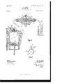
- Figure 1 is a vertical central section through the preferred form of explosion-chamber constructed after my invention, showing same attached to a suitable engine-casing provided with suitable power-transmitting parts.
- FIG. 2 is an enlarged detail view of the mechanism for operat ng the valve.
- Fig, 3 ma side view -of a portion of the explosion-chamber, showof explosion-chamber.
- Fig. 4 is a vertical central section through an alternative form
- Fig. 5 is a verticalcentral-section through.
- I formof explosion-chamber This figure also I chamber.
- FIG. 1 shows a longitudinal section through the measuring device used and tank for same.
- Fig. 6 is an enlarged detail view of the mechanism for operating the valve in the explosion-chainber shown in Fig. 5.
- .1 preferably usean explosion chamber the walls of which are constructed so as to be aircooled; but it must be distinctly understood t' ,liat;I do not confine myself to any particular construction of explosion-chamber for cooling purposes. It will :be understood from this that I may use a wat'er-jacket, if desired; but
- I preferably use an explosion-chamber A, constructed of asingle wall or shell, so'that same may be air-cooled.
- I B is the upper portion of the engine-casing, to which the explosion-chamber is suitably secured, and O the lower portion of same.
- ' D is the engine-shaft, the inner ends of which are keyed to thefly-wheels E, which by means .of the pin "F are secured'to the piston-rod G, provided with the'usual pistonhead H.
- a suitable valve J preferably springcontrolled.
- This valve is mechanically operated by any suitable means, such as a lever (and other parts hereinafter described,) -.pivoted atk to a suitable plate L, which is suitably secured to the head of the explosionv Keyed to the shaft D is a' spurgear M, which meshes with the spurwheel N, journaled onthe rod O, which has bearing in the" plate P, secured to one side of the engine-casing and the boss Q, which forms part of the engine-casing, as shown.
- the spurwheel N is preferably provided with a sleeve R, which incloses the boss Qa'nd has bearing thereon.
- U is an igniter, preferably an electric one, and V the delivery end of. the conduit V of the fuel-measuring device, which enters said explosion-chamber through opening W.
- a suitable main exhaust-port X Formed in one side of the preferred form of explosion-chamber A is a suitable main exhaust-port X, which is designed to be fully opened when the piston-head H is-at the limit of its outward movement.
- the main exhaust-port comprises anumber of holes a, which'lead from the explosion-chamber.
- I may, if desired, construct the main exhaust-port in several ways Without departing from the spirit of my invention; but in order to prevent the packing-rings h, with which the usual piston-head is provided, from being obstructed in their movement I preferably provide the series of holes a, before described.
- the shaft D and its connecting parts are of course operated by hand in starting up the engine.
- the valve is kept open while the piston-head H moves to thelimit 3 of its inward stroke, thus discharging a second volume of the waste products of combustion through the valve.
- the said valve still remains open during the movement of the piston-head H from line 3 to approximately line 4, thus permitting a charge of pure air to rush into the explosion-chamber on top of the residue of the waste products of combustion therein, thus keeping same next the piston-head.
- the cam 2 es-- capes the roller T the said roller drops onto the uniform periphery of the sleeve R and rests in contact with same for the space 5 shown between the cam 2 and the other cam, thus permitting the said valve to be closed by its spring 1.
- the length of the space 5 is approximately indicated by the distance between the lines 4 and 6. During the length of this space the required charge of raw liquid fuel is discharged through the delivey end of the conduit of the fuel-measuring device into the explosionchamber into the body of pure air above the residue of the waste products of combustion.
- the cam 7 secured to or forming part of the sleeve R abuts the roller T the rod S is moved upward, depressing the lever K, so that the valve J is opened, and as the piston-head continues in its outward movement a volume of fresh air simultaneously rushes into the explosion-chamber.
- the piston-head again opens the main exhaustport X and until it closes same on its return movement the residue of the waste products of combustion are removed from the explosion chamber.
- piston-head reaches the limit of its outward stroke the cam 9, secured to or forming part 25 fuel-measuring device.
- valve J This operation permits the waste products of combustion to exhaust through said valve.
- the said valve is kept open while the piston-head moves to the limit of its inward stroke,thus dis- 1o charging a further volume of the waste projects of combustion from the explosion-chame her.
- the said valve is. still kept open until the piston-head moves outward to approximately the line 11, thus permitting a fresh charge of pure air to be drawn into the explosion-chamber.
- the pistonhead reaches the approximate line 11 the roller T escapes the cam 9 and rests upon the. uniform periphery of the sleeve R, thus clos- 2o ing the valve J.
- a device for measuring and delivering a charge of raw gasolene directly into the explosion-chamber is an essential element ofv my invention.
- the preferred form of fuel-measurer is broadly described as follows: 13. is any suit ablecasing provided with two ducts l t and a central passage-way 15, in which central passage-way operates any suitable valve 16.
- v V is a conduit leading from any suitable .reser-
- the reservoir is preferably constructed so that the fuel therein may be under atmospheric pressure. Immediately the pressure within the explosionchamber is below that of the atmosphere the 5 5 gasolene isforced inthe direction indicated by arrow through the fuel-measurer into the ex-. plosion-chamber. Immediately the charge is being compressed inthe explosion-chamber thepressure therein presses againstthe gasoe o lene in the conduit V, thus preventing same from passing into the explosion-chamber during thls operation. This pressure on the gasolene moves the valve 16 into theposition'shown 111 Fig. 7 5 thus preventingthe gasolene inrthe,
- the essential elements of my invention are i an explosion-chamber provided with a separate inlet for fuel, a single valve which performs the function of. carrying off a portion of the waste products of combustion and a further function of introducing fresh air into the explosion-chamber, the piston-head operatingin relation to said valve, means for measuring and delivering a charge of raw gasolene. into said. explos1onchamber, and means for operating said valve as described.
- the spur-gear M revolves twice as often as.
- valve means whereby the valve is opened to permit the piston-head to remove waste products of combustion from explosion-chamber during one of its inward movements, and kept open.
- valve is opened to permit the piston-head to remove waste products of combustion from explosion-chamber during one of its inward movements, and kept open whilethe piston-head is moved a certain distance outward so as to admit fresh air into the explosion-chamber, then closed while the raw liquid fuel is fed into the explosion-chamber, and then opened and kept open until the piston-head has moved to the limit of its outward stroke and opened the main exhaust-port, so as to remove the residue of the waste products of combustion, and then closed when the piston-head closes said exhaust-port on the return stroke.
- a bearing a revolving member operating on said bearing; a rod resting against said revolving member, and means intermediate said rod and said valve, the said revolving member being constructed so as to operate said rod and said intermediate means so that the said valve is opened to permit the piston-head to remove waste products of combustion from the explosion-chamber during one of its inward movements, and kept open while the piston-head is moved a certain distance outward so as to admit fresh air into the explosioncharnber, then closed while the raw liquid fuel IIO head closes said exhaust-port on the return.
Landscapes
- Engineering & Computer Science (AREA)
- Chemical & Material Sciences (AREA)
- Combustion & Propulsion (AREA)
- Mechanical Engineering (AREA)
- General Engineering & Computer Science (AREA)
- Output Control And Ontrol Of Special Type Engine (AREA)
Description
No. 753,003 PATENTED FEB. 23, 1904.
A. G. RONAN.
GAS ENGINE.
APPLIGATION FILED JAN. 24, 1903.
N0 MODEL. 2 SHEETS-SHEET 1.
JC IB PATENTED FEB. 23, 1904.
A. G. RUNAN.
GAS ENGINE.
APPLIGATION FILED JAN. 24, 1903.
N0 MODEL.
351 I 0/ I I I a I II 1 I II I I I I I II I I I I I I I I I I Wk I r .1 4E k .1 I I --.I I-I I. I
Witnesses.
TNK div-s warms no Fuorou mrmsamnmx n. b.
' 1'0 alliwhom it may concern.-
. UNITED STATES Patented February 23, 1904.
PATENT OFFICE,
' ANSON GROVES RONAN; OF TORONTO, CANADA.
GAS-ENGINE.
SPECIFICATION forming part of Letters Patent No. 753,003, dated February 23, 1904. Application filed Jannary24, 1903. Serial No. 140,378. (No model.)
Be it known that I, Anson Gnovns Rowan,
a subject of the King ofGreat Britain, residing in the city of Toronto, in the county of York and Province of Ontario, Canada, have invented certain new and useful Improveare, first, to remove as much as possible of g the waste products of combustion from the explosion-chamber, so that the succeeding charges'of the explosive mixture will be as free as possible of the spent gases, thus pro- ,ducing' a powerful engine and one that can be easily and quickly started, and, secondly, to reduce the number of valves used in gas-engines; and it consists,,essentially, of a suitable explosion-chamber provided with a'valve controlling a port therefrom tothe atmosphere and a separate opening for raw liquid fuel, means combined with said explosion-chamber for operating said valve so that same will perform one function of permitting the escape j of waste products of combustion from the explosion-chamber ,and a further function of admitting pure airthereinto, and the further combination of elements, as hereinafter more particularly explained. I preferably make use of the piston-head to operateduring its suction-stroke or portion thereof the measuring means containing the raw liquid fuel; bu tI lay claim tonsing any means for feeding saidvfuel to the engine.
Figure 1 is a vertical central section through the preferred form of explosion-chamber constructed after my invention, showing same attached to a suitable engine-casing provided with suitable power-transmitting parts. Fig.
2 is an enlarged detail view of the mechanism for operat ng the valve. Fig, 3 ma side view -of a portion of the explosion-chamber, showof explosion-chamber.
ing the form of main exhaust-port usedin the preferred form of cylinder. Fig, 4 is a vertical central section through an alternative form Fig. 5 is a verticalcentral-section through. another alternative I formof explosion-chamber. This figure also I chamber.
shows a longitudinal section through the measuring device used and tank for same.
Fig; 6 is an enlarged detail view of the mechanism for operating the valve in the explosion-chainber shown in Fig. 5. v
In the drawing, like characters of reference indicate corresponding parts in each figure.
.1 preferably usean explosion chamber the walls of which are constructed so as to be aircooled; but it must be distinctly understood t' ,liat;I do not confine myself to any particular construction of explosion-chamber for cooling purposes. It will :be understood from this that I may use a wat'er-jacket, if desired; but
' I preferably use an explosion-chamber A, constructed of asingle wall or shell, so'that same may be air-cooled. I B is the upper portion of the engine-casing, to which the explosion-chamber is suitably secured, and O the lower portion of same.
' D is the engine-shaft, the inner ends of which are keyed to thefly-wheels E, which by means .of the pin "F are secured'to the piston-rod G, provided with the'usual pistonhead H. Preferably in the head of the explosion-chamber I construct an opening I and operate therein in order to open and close said opening a suitable valve J, preferably springcontrolled. This valve is mechanically operated by any suitable means, such as a lever (and other parts hereinafter described,) -.pivoted atk to a suitable plate L, which is suitably secured to the head of the explosionv Keyed to the shaft D is a' spurgear M, which meshes with the spurwheel N, journaled onthe rod O, which has bearing in the" plate P, secured to one side of the engine-casing and the boss Q, which forms part of the engine-casing, as shown. The spurwheel N is preferably provided with a sleeve R, which incloses the boss Qa'nd has bearing thereon. I
S is a rod held in any suitable bearings, against the upper end of which rests the lever K, In the lower end of the rod S issuitably pivoted a roller T, which operates upon the sleeve R and its cams, as hereinafter described.
U is an igniter, preferably an electric one, and V the delivery end of. the conduit V of the fuel-measuring device, which enters said explosion-chamber through opening W.
The fuel-measuring device I use in connection with my engine is fully described in my application, Serial No. 116,559, filed July 22, 1902.
Formed in one side of the preferred form of explosion-chamber A is a suitable main exhaust-port X, which is designed to be fully opened when the piston-head H is-at the limit of its outward movement. As will be seen, the main exhaust-port comprises anumber of holes a, which'lead from the explosion-chamber. I may, if desired, construct the main exhaust-port in several ways Without departing from the spirit of my invention; but in order to prevent the packing-rings h, with which the usual piston-head is provided, from being obstructed in their movement I preferably provide the series of holes a, before described. The shaft D and its connecting parts are of course operated by hand in starting up the engine. I will suppose that an explosion has already taken place and forced the pistonhead H down into the position shown in Fig. 1. As the piston-head opens the main exhaustport X, waste products of combustion exhaust through the several holes a of same, and by the time the piston-head moves upward and closes said main exhaust-port the major portion of the Waste, products of combustion have passed from the explosion-chamber. Simultaneously the piston-head H closes the main exhaust-port X the valve J is opened by reason of the cam 2, secured to or forming part of the sleeve R, abutting the roller T, thus/moving the rod S upward in the direction indicated by ar. row and depressing the end I) of the lever K- The valve is kept open while the piston-head H moves to thelimit 3 of its inward stroke, thus discharging a second volume of the waste products of combustion through the valve. The said valve still remains open during the movement of the piston-head H from line 3 to approximately line 4, thus permitting a charge of pure air to rush into the explosion-chamber on top of the residue of the waste products of combustion therein, thus keeping same next the piston-head. Immediately the cam 2 es-- capes the roller T the said roller drops onto the uniform periphery of the sleeve R and rests in contact with same for the space 5 shown between the cam 2 and the other cam, thus permitting the said valve to be closed by its spring 1. The length of the space 5 is approximately indicated by the distance between the lines 4 and 6. During the length of this space the required charge of raw liquid fuel is discharged through the delivey end of the conduit of the fuel-measuring device into the explosionchamber into the body of pure air above the residue of the waste products of combustion. Immediately the cam 7 secured to or forming part of the sleeve R, abuts the roller T the rod S is moved upward, depressing the lever K, so that the valve J is opened, and as the piston-head continues in its outward movement a volume of fresh air simultaneously rushes into the explosion-chamber. the piston-head again opens the main exhaustport X and until it closes same on its return movement the residue of the waste products of combustion are removed from the explosion chamber. Simultaneously the pistonhead H closes the main exhaust-port X the roller T escapes the cam 7 and rests again upon the periphery of the sleeve R for the space 8 between the cams 2 and 7, thus closing the Valve. During the continued movement of the piston-head the explosive mixture is compressed, ignited, and exploded, and the piston-head H forced down into the position shown in Fig. 1, when the above-described cycle takes place again. By opening the valve J by the cam 7 thus permitting pure air to rush into the explosion-chamber from the atmosphere, it will be seen thatI am assured of the proper proportion of air to be mixed with the raw gasolene in order to provide an explosive mixture.
From this specification it will be distinctly understood that in my preferred form of in- From the time vention I actually keep the valve J open and the main exhaust-port X open, while I have within the explosion-chamber a charge of raw gasolene. The piston-head H is of course timed to'close the main exhaust-port X before any of the gasolene escapes from the explosion= chamber therethrough.
On reference to Fig. 4: it will be seen that I provide the explosion-chamber with two main exhaust-ports X and X for the purpose of enabling me to exhaust the waste products of combustion from the explosion-chamber as quickly as possible. The best practice in gasolene-engine construction is to get rid of the waste products of combustion as soon as possible in order to keep the explosion-chamber at the minimum temperature.
. By dispensing with the usual valve-chamber and inserting the igniter into the explosion-chamber directly above the piston-head therein it will be understood that the ignition and explosion of the explosive mixture takes place wholly within the explosion-chamber, thus increasing the efliciency of the engine. By reducing the number of valves used and doing away with the ordinary valve-chamber I reduce the weight and expense of gas-engines. r
In the alternative form of explosion-chamber shown in Fig. 5 I dispense with an ex-.
piston-head reaches the limit of its outward stroke the cam 9, secured to or forming part 25 fuel-measuring device.
5 voir V to the fuel-measurer.
' of the sleeve R, abuts theroller T, suitablyjournaled in the lower end of the rods", and raises said rod upward in the direction indicated by arrow, thus depressing the lever K,
5 so as to open the valve J. This operation permits the waste products of combustion to exhaust through said valve. The said valve is kept open while the piston-head moves to the limit of its inward stroke,thus dis- 1o charging a further volume of the waste projects of combustion from the explosion-chame her. The said valve is. still kept open until the piston-head moves outward to approximately the line 11, thus permitting a fresh charge of pure air to be drawn into the explosion-chamber. Simultaneously the pistonhead reaches the approximate line 11 the roller T escapes the cam 9 and rests upon the. uniform periphery of the sleeve R, thus clos- 2o ing the valve J. As the piston-headcou- 0 scribes the cycle operating in the alternative form of explosion-chamber shown in Fig-5. As will be understood, the pressure within the explosion-chamber during the outward movement of the piston-head H when an ex- 3 5 plosion is not taking. place is much below that of the outside atmosphere, thus permitting the fuel-measuring device to operate so as to measure and feed the required amount of raw gasolene into said explosion-chamber.
40 A device for measuring and delivering a charge of raw gasolene directly into the explosion-chamber is an essential element ofv my invention.
The preferred form of fuel-measurer is broadly described as follows: 13. is any suit ablecasing provided with two ducts l t and a central passage-way 15, in which central passage-way operates any suitable valve 16.v V is a conduit leading from any suitable .reser- The reservoir is preferably constructed so that the fuel therein may be under atmospheric pressure. Immediately the pressure within the explosionchamber is below that of the atmosphere the 5 5 gasolene isforced inthe direction indicated by arrow through the fuel-measurer into the ex-. plosion-chamber. Immediately the charge is being compressed inthe explosion-chamber thepressure therein presses againstthe gasoe o lene in the conduit V, thus preventing same from passing into the explosion-chamber during thls operation. This pressure on the gasolene moves the valve 16 into theposition'shown 111 Fig. 7 5 thus preventingthe gasolene inrthe,
measuring device and its connecting passage ways and conduits being forced therefrom.
The operating parts of the engine will of course (be provided with oil in the usual manner.
I do not confine myself to means shown and described for operating the valve J.
The essential elements of my invention are i an explosion-chamber provided with a separate inlet for fuel, a single valve which performs the function of. carrying off a portion of the waste products of combustion and a further function of introducing fresh air into the explosion-chamber, the piston-head operatingin relation to said valve, means for measuring and delivering a charge of raw gasolene. into said. explos1onchamber, and means for operating said valve as described.
I donot confine myself to the construction of the parts herein shown and described, as same may be altered in many ways without departing from the spirit of my invention.
The spur-gear M revolves twice as often as.
the spur-wheelN.
What I claim as my invention is 1. The combination with an explosion-chamber, provided with an opening through which fuel only is fed, and a main exhaust port opened and closed by the piston-head; said pis-z ton-head; means for feeding raw liquidfuel into said expl0sionchamber through said fuel- Y opening, and a valve controlling a port from said explosion-chamber to the atmosphere, of:
means whereby the valve is opened to permit the piston-head to remove waste products of combustion from explosion-chamber during one of its inward movements, and kept open.
while the piston-head isv moved a certain distance outwardso as to admit fresh air into the explosion-chamber, then closed while the raw liquid fuelis fed. into the explosion-chamber, and then opened and kept open until the piston-head has moved to the limit of its outward stroke and opened the main exhaust-port, so
as to removethe residue ofthe waste products. of combustion, and then closed when the pis-- ton-head closes said exhaust-port on the return stroke. r
2. The combination with an explosion-chamber, provided with an opening through which fuelonly. is fed,. and a main exhaustrport opened and closed by the piston-head; said piston-head; means operated .hy the suction.
strokeor portion thereof of said piston-head, forfeedingraw liquid fuel into said explosionchamber through. said fuel opening, and a valve controlling a port from said explosion chamber to the atmosphere, of meansv whereby the valve. is opened to permit the pistonhead to remove waste products of combustion from explosion-chamberduring one of its .inward movements, and kept open while the piston-head is moveda certain distance outward so as 1 to admit fresh air intothe explosionchamber, then closed while the raw liquid fuel is fed into the explosion-chamber; and then opened and kept open until the piston-head has moved to the limit of its outward stroke and opened the main exhaust-port, so as to remove the residue of the waste products of combustion, and then closed when the piston-head closes said exhaust-port on the return stroke.
3. The combination with an explosion-chamber, provided with an opening through which fuel only is fed, and a main exhaust port opened and closed by the piston-head; said piston-head; a valve controlling a port from said explosion chamber to the atmosphere, and means whereby said valve is opened to permit the piston-head to remove waste products of combustion from the explosion-chamber during one of its inward movements, and kept open while the piston-head is moved a certain distance outward so as to admit fresh air into the explosion-chamber, then closed while the raw liquid fuel is fed into the explosion-chamber, and then opened and kept open until the piston-head has moved to the limit of its outward stroke and opened the main exhaustport, so as to remove the residue of the waste products of combustion, and then closed when the piston-head closes said exhaust-port on the return stroke, of means for measuring and delivering a charge of raw liquid fuel into said explosion-chamber through said fuel-opening.
4. The combination with an explosion-chamber, provided with an opening through which fuel only is fed, and a main exhaust-port, opened and closed by the piston-head; said piston-head; a valve controlling a port from said explosion chamber to the atmosphere, and means whereby said valve is opened to permit the piston-head to remove waste products of combustion from the explosion-chamber during one of its inward movements, and kept open while the piston-head is moved a certain distance outward so as to admit fresh air into the explosion-chamber, then closed while the raw liquid fuel is fed into the explosion-chamber, and then opened and kept open until the piston-head has moved to the limit of its outward stroke and opened the main exhaust-port, so as to remove the residue of the waste products of combustion, and then closed when the piston-head closes said exhaust-port on the return stroke, of means, operated by the. suction-stroke or portion thereof of said pistonhead, for feeding raw liquid fuel into said explosion-chamber through said fuel-opening.
5. The combination with an explosion-chamber, provided with an opening through which fuel only is fed, and a main exhaust-port opened and closed by the piston-head; said pistonhead; means for feeding raw liquid fuel into said explosion chamber through said fuelopening, and a valve, situated in the head of the explosion chamber, controlling a port from said explosion-chamber to the atmosphere, of
means whereby the valve is opened to permit the piston-head to remove waste products of combustion from explosion-chamber during one of its inward movements, and kept open whilethe piston-head is moved a certain distance outward so as to admit fresh air into the explosion-chamber, then closed while the raw liquid fuel is fed into the explosion-chamber, and then opened and kept open until the piston-head has moved to the limit of its outward stroke and opened the main exhaust-port, so as to remove the residue of the waste products of combustion, and then closed when the piston-head closes said exhaust-port on the return stroke.
6. The combination with an explosion-chamber, provided with an opening through which fuel only is fed, and a main exhaust-port opened and closed by the piston-head; said piston head; means for feeding raw liquid fuel into said explosion chamber through said fuelopening, and a valve controlling a port from said explosion-chamber to the atmosphere, of a bearing; a revolving member operating on said bearing, and means intermediate said revolving member and said valve, the said revolving member being constructedso as to operate said intermediate means so that the said opened and kept open until the piston-head fuel only is fed, and a main exhaust-port opened and closed by the piston-head; said pistonhead; means for feeding raw liquid fuel into said explosion chamber through said fuelopening, and a valve controlling a port from said explosion-chamber to the atmosphere, of
a bearing; a revolving member operating on said bearing; a rod resting against said revolving member, and means intermediate said rod and said valve, the said revolving member being constructed so as to operate said rod and said intermediate means so that the said valve is opened to permit the piston-head to remove waste products of combustion from the explosion-chamber during one of its inward movements, and kept open while the piston-head is moved a certain distance outward so as to admit fresh air into the explosioncharnber, then closed while the raw liquid fuel IIO head closes said exhaust-port on the return.
stroke.
In testimony whereof I have signed my name to this specification in the presence of two sub- 10 scribing Witnesses.
ANSON GROVES RONAN.
Witnesses:
EGERTON R. CASE, W. H. SMITH.
Publications (1)
| Publication Number | Publication Date |
|---|---|
| US753003A true US753003A (en) | 1904-02-23 |
Family
ID=2821496
Family Applications (1)
| Application Number | Title | Priority Date | Filing Date |
|---|---|---|---|
| US753003D Expired - Lifetime US753003A (en) | Anson groves ronan |
Country Status (1)
| Country | Link |
|---|---|
| US (1) | US753003A (en) |
-
0
- US US753003D patent/US753003A/en not_active Expired - Lifetime
Similar Documents
| Publication | Publication Date | Title |
|---|---|---|
| US676449A (en) | Gas, petroleum, or like internal-combustion engine. | |
| US820285A (en) | Oil-engine. | |
| US753003A (en) | Anson groves ronan | |
| US1160419A (en) | Internal-combustion engine. | |
| US1068173A (en) | Combustion-engine. | |
| US694090A (en) | Gas, gasolene, or inflammable-vapor engine. | |
| US785166A (en) | Internal-combustion engine. | |
| US1237312A (en) | Internal-combustion engine. | |
| US1196158A (en) | sawtelle | |
| US454936A (en) | atkinson | |
| US1168331A (en) | Internal-combustion engine. | |
| US878647A (en) | Internal-combustion engine. | |
| US642043A (en) | Gas-engine. | |
| US1297350A (en) | Internal-combustion engine. | |
| US335462A (en) | Gas engine | |
| US652724A (en) | Gas-engine. | |
| US1185874A (en) | Starting mechanism for internal-combustion engines. | |
| US597749A (en) | Differential gas-motor | |
| US1170966A (en) | Engine. | |
| US899618A (en) | Starting device for gasolene-engines. | |
| US576604A (en) | Gas engine | |
| USRE10951E (en) | Landw | |
| US316868A (en) | Cabl benz | |
| US614114A (en) | Febvke | |
| US825867A (en) | Combined intake and exhaust valve for gas-engines. |