US7523758B2 - Dishwasher having rotating zone wash sprayer - Google Patents
Dishwasher having rotating zone wash sprayer Download PDFInfo
- Publication number
- US7523758B2 US7523758B2 US11/026,770 US2677004A US7523758B2 US 7523758 B2 US7523758 B2 US 7523758B2 US 2677004 A US2677004 A US 2677004A US 7523758 B2 US7523758 B2 US 7523758B2
- Authority
- US
- United States
- Prior art keywords
- wash
- dishwasher according
- spray head
- chamber
- manifold
- Prior art date
- Legal status (The legal status is an assumption and is not a legal conclusion. Google has not performed a legal analysis and makes no representation as to the accuracy of the status listed.)
- Expired - Lifetime, expires
Links
- 239000007921 spray Substances 0.000 claims abstract description 158
- 239000007788 liquid Substances 0.000 claims abstract description 73
- 238000005406 washing Methods 0.000 claims description 8
- 230000002093 peripheral effect Effects 0.000 claims 20
- 238000005507 spraying Methods 0.000 claims 3
- 230000000694 effects Effects 0.000 claims 2
- 230000001154 acute effect Effects 0.000 claims 1
- 238000004851 dishwashing Methods 0.000 abstract description 6
- 230000000712 assembly Effects 0.000 description 16
- 238000000429 assembly Methods 0.000 description 16
- 238000004140 cleaning Methods 0.000 description 11
- 239000012530 fluid Substances 0.000 description 8
- XLYOFNOQVPJJNP-UHFFFAOYSA-N water Substances O XLYOFNOQVPJJNP-UHFFFAOYSA-N 0.000 description 8
- 239000002689 soil Substances 0.000 description 4
- 238000010411 cooking Methods 0.000 description 3
- 239000002245 particle Substances 0.000 description 3
- 230000000717 retained effect Effects 0.000 description 2
- 241001640558 Cotoneaster horizontalis Species 0.000 description 1
- 239000000853 adhesive Substances 0.000 description 1
- 230000001070 adhesive effect Effects 0.000 description 1
- 230000002708 enhancing effect Effects 0.000 description 1
- 239000011521 glass Substances 0.000 description 1
- 230000014759 maintenance of location Effects 0.000 description 1
- 230000007246 mechanism Effects 0.000 description 1
- 238000012986 modification Methods 0.000 description 1
- 230000004048 modification Effects 0.000 description 1
- 230000007704 transition Effects 0.000 description 1
- 239000013598 vector Substances 0.000 description 1
- 238000003466 welding Methods 0.000 description 1
- 229910000859 α-Fe Inorganic materials 0.000 description 1
Images


Classifications
-
- A—HUMAN NECESSITIES
- A47—FURNITURE; DOMESTIC ARTICLES OR APPLIANCES; COFFEE MILLS; SPICE MILLS; SUCTION CLEANERS IN GENERAL
- A47L—DOMESTIC WASHING OR CLEANING; SUCTION CLEANERS IN GENERAL
- A47L15/00—Washing or rinsing machines for crockery or tableware
- A47L15/42—Details
- A47L15/4214—Water supply, recirculation or discharge arrangements; Devices therefor
- A47L15/4219—Water recirculation
- A47L15/4221—Arrangements for redirection of washing water, e.g. water diverters to selectively supply the spray arms
-
- A—HUMAN NECESSITIES
- A47—FURNITURE; DOMESTIC ARTICLES OR APPLIANCES; COFFEE MILLS; SPICE MILLS; SUCTION CLEANERS IN GENERAL
- A47L—DOMESTIC WASHING OR CLEANING; SUCTION CLEANERS IN GENERAL
- A47L15/00—Washing or rinsing machines for crockery or tableware
- A47L15/14—Washing or rinsing machines for crockery or tableware with stationary crockery baskets and spraying devices within the cleaning chamber
- A47L15/16—Washing or rinsing machines for crockery or tableware with stationary crockery baskets and spraying devices within the cleaning chamber with rigidly-mounted spraying devices
-
- A—HUMAN NECESSITIES
- A47—FURNITURE; DOMESTIC ARTICLES OR APPLIANCES; COFFEE MILLS; SPICE MILLS; SUCTION CLEANERS IN GENERAL
- A47L—DOMESTIC WASHING OR CLEANING; SUCTION CLEANERS IN GENERAL
- A47L15/00—Washing or rinsing machines for crockery or tableware
- A47L15/14—Washing or rinsing machines for crockery or tableware with stationary crockery baskets and spraying devices within the cleaning chamber
- A47L15/18—Washing or rinsing machines for crockery or tableware with stationary crockery baskets and spraying devices within the cleaning chamber with movably-mounted spraying devices
- A47L15/22—Rotary spraying devices
- A47L15/23—Rotary spraying devices moved by means of the sprays
-
- A—HUMAN NECESSITIES
- A47—FURNITURE; DOMESTIC ARTICLES OR APPLIANCES; COFFEE MILLS; SPICE MILLS; SUCTION CLEANERS IN GENERAL
- A47L—DOMESTIC WASHING OR CLEANING; SUCTION CLEANERS IN GENERAL
- A47L15/00—Washing or rinsing machines for crockery or tableware
- A47L15/42—Details
- A47L15/4278—Nozzles
- A47L15/428—Rotary nozzles
Definitions
- the present invention relates to dishwashers.
- the invention relates to a dishwasher having a zone wash manifold with rotating sprayers.
- the invention relates to a dishwasher having an enhanced spray pattern for optimizing the cleaning effectiveness of the dishwasher.
- the invention relates to a dishwasher having an improved cooking utensil cleaning capability.
- Modem dishwashers include a tub and an upper and lower rack or basket for supporting soiled dishes within the tub.
- a pump is provided for re-circulating wash liquid throughout the tub to remove soils from the dishes.
- larger dishes such as casserole dishes which have a propensity to be heavily soiled are carried on the lower rack and lighter soiled dishes such as cups and glasses are provided on an upper rack.
- the racks are generally configured to be moveable in or out of the tub for loading and unloading.
- a lower wash arm rotates about a vertical axis and is provided beneath the lower rack for cleaning the dishes on the lower rack and an upper wash arm is provided beneath the upper rack for cleaning the dishes on the upper rack.
- Dishes in the upper rack receive somewhat uniform wash treatment and dishes in the lower rack receive somewhat uniform wash treatment.
- lightly soiled dishes in either dish rack are subject to the same wash performance as the highly soiled dishes in the same wash rack, which can lead to poor wash performance of the highly soiled dishes.
- Another problem associated with the modem dishwasher is that to achieve optimal wash performance of heavily soiled, larger dishes, the dishes may need to be loaded with the surface that needs to be washed face down.
- the face down approach allows the lower spray arm to reach the heavily soiled surface.
- the dishwasher could be provided with a second wash zone that allowed the heavily soiled dishes to be loaded in an upright position, thereby optimizing the number of dishes that can be loaded in the dishwasher on any given cycle. It would also be advantageous if the dishwasher allowed for a customized wash cycle option which optimized the use of the second wash zone.
- a stationary zone wash spray manifold in combination with a rotating spray arm assembly is highly effective in washing heavily soiled dishes which are loaded in an upright position.
- the combination of spray from a conventional rotating spray arm assembly and a zone wash spray manifold contributes to high water usage. While the cleaning of the heavily soiled dishes may be optimized with this assembly, the high volume of wash liquid required results in less volume delivered to other spray assemblies and potentially less effective cleaning of other dishes.
- the stationary manifold also limits the size of the wash zone, thereby limiting the effectiveness of the cleaning operation.
- a dishwasher comprises a tub defining a wash chamber for receiving utensils for washing and a manifold located within the wash chamber and comprising at least one rotating spray head comprising at least one outlet for providing a circulating spray of wash liquid into the wash chamber to provide a wash zone.
- the manifold can be mounted to the tub.
- a spray arm can be included and configured to rotate within the tub and spray a flow of wash liquid into the wash chamber thereby providing another wash zone.
- the pressure/force of the wash liquid exiting the at least one outlet is greater than for a similarly configured non-rotating spray head, and the area covered by the circulating spray is greater than a similarly configured non-rotating spray head.
- the at least one rotating spray head can comprise a front plate and a back plate to define a chamber therebetween, which is in fluid communication with the manifold such that wash liquid passing through the manifold can be transferred to the rotating spray head.
- the at least one outlet is arranged on the front plate such that the wash liquid exiting the at least one opening causes the rotating spray head to rotate.
- One or more arcuate vanes can be located on the rear surface of the front plate such that the wash liquid entering the interior of the rotating spray head will contact the vane and cause the spray head to rotate.
- the vane can also be arranged such that it directs the wash liquid to the at least one outlet.
- the at least one spray head can be rotatably attached to the manifold through a shaft, which can have the form of a bearing hub inserted through the axial opening of the back plate and attached to the manifold with a fastener.
- the at least one rotating spray head can comprise a plurality of outlets, which can be distributed adjacent to and away from an axis of rotation of the at least one rotating spray head.
- the manifold can have a plurality of wash liquid conduits for supplying a plurality of spray heads.
- FIG. 1 is a perspective view of a dishwasher having an interior with multiple wash zones in accordance with the present invention.
- FIG. 2 is a schematic, cross-sectional view of the dishwasher shown in FIG. 1 , showing the dish racks mounted in the tub, upper and lower spray arm assemblies, a spray manifold, and a third-level spray assembly having a control valve as contemplated by the present invention.
- FIG. 3 is a front elevational view of a spray manifold in accordance with the exemplary embodiment of the present invention.
- FIG. 4A is a schematic view of a first position of a valve for selectively diverting wash liquid to a supply tube in accordance with the exemplary embodiment of the present invention.
- FIG. 4B is a schematic view of a second position of a valve for selectively diverting wash liquid to a spray manifold in accordance with the exemplary embodiment of the present invention.
- FIG. 5 is a schematic view of a valve and actuator as contemplated by the present invention.
- FIG. 6 is an enlarged perspective view of a zone wash spray manifold with rotating spray heads according to the invention.
- FIG. 7 is an enlarged perspective view of the zone wash spray manifold of FIG. 6 illustrating its position relative to a lower dish rack.
- FIG. 8A is an enlarged perspective view of a portion of the zone wash spray manifold illustrated in FIG. 6 .
- FIG. 8B is a sectional view of a taken along view line 8 B- 8 B of FIG. 8A .
- FIG. 8C is an enlarged plan view of the interior of a rotating spray head illustrated in FIG. 6 .
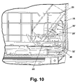
- FIG. 9 is a perspective view of a pair of exemplary cooking utensils supported in the lower dish rack of FIG. 7 and oriented relative to the zone wash spray manifold for optimized cleaning.
- FIG. 10 is a side view of the exemplary cooking utensils supported in the lower dish rack illustrated in FIG. 9 showing the spray pattern from the lower spray arm assembly and zone wash spray manifold with rotating spray heads.
- FIGS. 1 and 2 illustrate an exemplary embodiment of a multiple wash zone dishwasher 10 in accordance with the present invention.
- the dishwasher 10 comprises several elements found in a conventional dishwasher, including an interior tub 12 having a top wall 13 , a bottom wall 14 , two side walls 15 , 16 , a front wall 17 , and a rear wall 18 , which form an interior wash chamber or dishwashing space 19 for washing dishes.
- the front wall 17 can be replaced with an opening 11 which can be selectively closed with a door 20 , which can be pivotally attached to the dishwasher 10 for providing accessibility to the dishwashing space 19 for loading and unloading dishes or other washable items.
- the present invention is described in terms of a conventional dishwashing unit as illustrated in FIG. 1 , it can also be implemented in other types of dishwashing units such as in-sink dishwashers or drawer dishwashers.
- the bottom wall 14 of the dishwasher can be sloped to define a lower tub region or sump 20 of the tub 12 .
- a pump assembly 21 can be located in or around a portion of the bottom wall 14 and in fluid communication with the sump 20 to draw wash liquid from the sump 20 and to pump the liquid to at least a lower spray arm assembly 22 . If the dishwasher has a mid-level spray arm assembly 23 and/or an upper spray arm assembly 24 , liquid can be selectively pumped through a fluidly-connected lower supply tube 25 and upper supply tube 58 to the assemblies 22 - 24 for selective washing.
- the lower supply tube 25 extends generally rearwardly from the pump assembly 21 to the rear wall 18 of the tub and upwardly to supply wash liquid to the mid-level spray arm assembly 23 .
- the upper supply tube 58 extends generally upwardly from the lower supply tube 25 to supply wash liquid to the upper spray arm assembly 24 .
- the upper spray arm assembly 24 is fluidly connected to the upper supply tube 58 through a top wall spray tube 60 , which extends generally along and parallel to the top wall 13 .
- the lower spray arm assembly 22 is positioned beneath a lower dish rack 26
- the mid-level spray arm assembly 23 is positioned between an upper dish rack 27 and the lower dish rack 26
- the upper spray arm assembly 24 is positioned above the upper dish rack 27 .
- the lower spray arm assembly 22 is configured to rotate in the tub 12 and spray a flow of wash liquid in a generally upward direction over a portion of the interior of the tub 12 .
- the spray from the lower spray arm assembly 22 is typically directed to providing a wash for dishes located in the lower dish rack 26 .
- the mid-level spray arm assembly 23 can also be configured to rotate in the dishwasher 10 and spray a flow of wash liquid in a generally upward direction over a portion of the interior of the tub 12 .
- the spray from the mid-level spray arm assembly 23 is directed to dishes in the upper dish rack 27 .
- the upper spray arm assembly 24 generally directs a spray of wash water in a generally downward direction and helps wash dishes on both dish racks 26 , 27 .
- the spray of wash liquid from the lower spray arm assembly 22 defines a first “wash zone” 50 which, in the embodiment illustrated in FIG. 2 , extends generally upwardly from the lower spray arm assembly 22 to a region extending somewhat above the lower dish rack 26 .
- the spray of wash liquid from the mid-level spray arm assembly 23 defines a second “wash zone” 52 which, in the embodiment illustrated in FIG. 2 , extends generally upwardly from the mid-level spray arm assembly 23 to a region generally coextensive with the upper dish rack 27 .
- the spray of wash liquid from the upper spray arm assembly 24 defines a third “wash zone” 54 which, in the embodiment illustrated in FIG. 2 , extends generally downwardly from the upper spray arm assembly 24 to a region generally coextensive with the upper dish rack 27 .
- the present invention further comprises a fourth “wash zone”, or more particularly, an intensified wash zone 28 .
- an intensified wash zone 28 is located adjacent the lower dish rack 26 toward the rear of the tub 12 , it could be located at virtually any location within the interior tub 12 .
- the intensified wash zone 28 has been designed to enable heavily soiled dishes, such as casserole dishes, to receive the traditional spray arm wash, as well as an additional concentrated wash.
- a dishwasher having such a zone will not only provide better washing performance for heavily soiled dishware, but will provide overall improved wash performance.
- the intensified wash zone 28 is achieved by selectively diverting wash liquid from the upper spray arm assemblies 23 , 24 to a vertically oriented spray manifold 29 positioned on the rear wall 18 of the interior tub 12 adjacent the lower dish rack 26 . In this way, a flow of wash liquid is directed toward the lower dish rack 26 from the manifold 29 , thereby defining the intensified wash zone 28 .
- the spray manifold 29 is not limited to this configuration; rather, the spray manifold 29 can be located in virtually any part of the interior tub 12 . For example, the manifold 29 could be moved up vertically along any portion of the wash liquid supply tube 25 such as to a position adjacent the upper dish rack 27 .
- the manifold 29 can be positioned beneath the lower dish rack 26 adjacent or beneath the lower wash arm assembly 22 .
- the illustrated configuration of the spray manifold 29 enables casserole dishes to be loaded in an upright position, to maximize or optimize the number of dishes that can be loaded in any given cycle.
- the spray manifold 29 is in fluid communication with the wash liquid supply tube 25 such that wash liquid can be selectively provided to the manifold 29 .
- the manifold 29 is configured to have two symmetrically opposing halves 31 , 32 positioned on opposite sides of the supply tube 25 with each half being configured to selectively receive wash liquid being pumped through the supply tube 25 .
- Each half 31 , 32 of the manifold 29 comprises a plurality of apertures 30 configured to spray wash liquid into the wash zone 28 .
- each half of the manifold 29 is configured with one or more passageways 33 to deliver wash liquid from the supply tube 25 to the apertures 30 .
- the wash liquid being pumped through the supply tube 25 will be under pressure as it passes through passageway 33 and out apertures 30 , thereby creating an intensified wash zone 28 .
- each half 31 , 32 of the spray manifold 29 comprises two substantially circular nozzles 34 , 35 having a plurality of apertures 30 arranged in a substantially circular pattern.
- Each aperture 30 has a substantially oval shape and can selectively be oriented at a predefined angle with respect to the nozzle or with respect to the spray manifold 29 .
- the spray manifold 29 can also extend across virtually any width of the interior wash tub 12 , or can be limited to extending to only one side of the supply tube 25 .
- the number of nozzles 34 , 35 can be selectively varied, as well as the height and positioning of each nozzle.
- the shape, size, angle, arrangement, and number of apertures 30 in the manifold 29 can be varied to provide a more concentrated wash zone.
- the manifold 29 can be configured to provide water flow to a particular zone, but the manifold can also be configured to provide a higher water flow.
- a valve 40 can be provided to selectively divert wash liquid from the upper spray arm assemblies 23 , 24 to the spray manifold 29 .
- the valve 40 is a magnetically actuatable diverter valve positioned in the supply tube 25 and is configured to direct the flow of wash liquid either through the supply tube 25 so it can reach the upper spray arm assemblies or through the spray manifold so it can reach the intensified wash zone 28 .
- the valve could also be designed to selectively divert water from the lower spray arm.
- the valve 40 comprises a housing 43 and two diverter objects such as magnetic balls 41 , 42 preferably having a ferrite core positioned within the housing and configured to be magnetically moved between a first position shown in FIG. 4A and a second position shown in FIG. 4B .
- the diverter objects 41 , 42 are magnetically positioned to substantially block passageway 33 associated with both halves 31 , 32 of the spray manifold. In this way, wash liquid is prevented from entering the manifold and is pushed through the supply tube 25 toward the mid-level and upper spray arm assemblies.
- the diverter objects 41 , 42 are magnetically positioned to substantially block the supply tube 25 , thereby allowing the wash liquid to enter both halves of the manifold through the passageway 33 .
- the exemplary embodiment illustrates a diverter valve using a plurality of magnetic objects, such as magnetic balls, to divert wash water between the upper spray arms and the manifold 29 , one of skill in the art will recognize that an arrangement of flapper valves, wedges, or other known water diverter mechanisms can also be used.
- an actuator 44 is positioned outside of the housing 43 and behind the tub 12 for magnetically moving the objects from the first position to the second position and vice versa.
- the actuator 44 comprises a magnet with sufficient strength to magnetically manipulate the diverter objects ( 41 , 42 ).
- the magnet could be a permanent magnet, electromagnet or any other type magnet configured to move the diverter objects.
- the actuator 44 can be configured to be mounted to the outside 46 of the tub 12 in a variety of configurations and can be configured to be in communication with and controlled by the dishwasher's control panel (not shown) or the wash programs associated with the dishwasher 10 . It should be recognized that to take advantage of the intensified wash zone, the dishwasher might be configured with customized wash cycle options that provide for zone actuation at optimal cycle intervals.
- FIG. 6 an alternate embodiment of the spray manifold 29 , identified hereinafter with the numeral 29 ′, is illustrated.
- the spray manifold 29 ′ shares many of the elements of the spray manifold 29 , and thus like elements will hereinafter be identified with like numerals.
- the main difference between the two embodiments is that the alternate embodiment has rotating nozzle assemblies 34 ′ and 35 ′, which permit a broader spray coverage area with a great spray pressure/force than what is achievable with the fixed spray nozzles.
- the spray manifold 29 ′ is in fluid communication with the wash liquid supply tube 25 , and comprises two symmetrically opposing halves 31 ′, 32 ′. Each half 31 ′, 32 ′ of the manifold 29 ′ is configured with one or more fluid passageways 33 ′.
- a valve 40 is fluidly connected to the manifold 29 ′ to selectively divert wash liquid from the upper spray arm assemblies 23 , 24 to the passageways 33 ′. As illustrated in FIGS. 7 , 9 , and 10 , the spray manifold 29 ′ is positioned within the wash chamber 19 to spray wash liquid against dishes supported in the lower dish rack 26 and within an intensified wash zone 28 ′.
- each half 31 ′, 32 ′ of the spray manifold 29 ′ comprises two substantially circular rotating nozzle assemblies 34 ′, 35 ′.
- Each nozzle assembly 34 ′, 35 ′ comprises a circular front plate 70 having an arcuate cross-section and a circular backplate 72 .
- the backplate 72 is provided with a circular aperture 76 extending coaxially therethrough.
- the front plate 70 and the backplate 72 are adapted for coaxial registry through a suitable well-known connection, such as an adhesive, an interference or snap fit, sonic welding, and the like, to join the front plate 70 and the backplate 72 in order to form an interior space 74 .
- the front plate 70 has a plurality of raised apertures 30 ′ arranged to direct a stream of wash liquid flowing therefrom in a generally tangential direction in order to impart a rotation to the nozzle assembly 34 ′, 35 ′.
- the orientation of each aperture 30 ′ relative to the surface of the front plate 70 and relative to a radial line extending between the aperture 30 ′ and the center of the front plate 70 is selected in order to impart a preferred rotation velocity and spray pattern to the nozzle assembly 34 ′, 35 ′.
- the number of nozzle assemblies 34 ′, 35 ′ can be selectively varied, as well as the height and positioning of each nozzle assembly 34 ′, 35 ′ along the front plate 70 .
- the shape, size, angle, arrangement, and number of apertures 30 ′ can also be selected to provide a more concentrated wash zone and/or a faster/slower rotation. It is preferred that the number of apertures 30 ′ be less than the number for the fixed nozzle assemblies 34 , 35 , which will result in an increase in the pressure/force of the wash liquid exiting the nozzles for a given supply pressure through the valve 40 . The increased pressure/force of the wash liquid can be used for better cleaning.
- the inner surface of the front plate 70 is also provided with a plurality of raised arcuate vanes or ribs 140 ( FIG. 8C ), extending from a common junction at the axial center of the front plate 70 outwardly toward the perimeter of the front plate 70 . While three vanes are illustrated, greater or fewer than three can be used. The curvature of the vanes aids in effecting the rotation of the nozzle assemblies 34 ′, 35 ′. The vanes 140 also direct the flow of water outwardly toward the apertures 30 ′.
- the passageway 33 ′ comprises a rear wall 80 and a front wall 82 to define an interior space 88 therebetween.
- the front wall 82 transitions to a circular mounting wall 84 having an opening 86 therein in fluid communication with the interior space 88 .
- the mounting wall 84 is configured for cooperative registry with the backplate 72 .
- the rear wall 80 is provided with a circular aperture 90 therethrough in coaxial alignment with the opening 86 .
- a bearing hub 100 is used along with a retaining pin 120 to rotationally retain the nozzle assemblies 34 ′, 35 ′ to the structure forming the passageway 33 ′.
- the bearing hub 100 is a generally cylindrical body comprising an annular bearing ring 102 on one end and an annular locking ring 108 on another end.
- a plurality of spaced extension fingers extend between the bearing ring 102 and locking ring 108 .
- An annular retaining flange 104 circumscribes the bearing ring 102 along a first side of the bearing ring 102 . The spaces between the fingers form fluid passages that establish fluid communication between the interior space 88 of the passageway 33 ′, 34 ′ and the interior space of the nozzle assemblies 34 ′, 35 ′.
- the retainer pin 120 is a generally circular body comprising a center shaft 122 transitioning coaxially at a first end to a circular, platelike flange 124 and at a second end to a somewhat conical locking tip 126 .
- the locking tip 126 is adapted to be inserted through the locking ring 108 for retention therein, with the center shaft 122 extending through the locking ring 108 .
- the diameter of the flange 124 on the retainer pin 120 is somewhat greater than the diameter of the aperture 90 in the back wall 80 .
- the diameter of the bearing ring 102 is somewhat smaller than the diameter of the aperture 76 in the backplate 72 to enable the backplate 72 to rotate relative to the bearing hub 100 .
- the diameter of the retaining flange 104 is somewhat greater than the diameter of the aperture 76 so that the bearing hub 100 is retained in the aperture 76 with the retaining flange 104 in the interior space 74 .
- the diameter of the opening 86 in the front wall 82 is somewhat smaller than the diameter of the bearing ring 102 .
- the bearing hub 100 is coupled to the nozzle assembly 34 ′, 35 ′ by inserting the extension fingers 106 through the aperture 86 so that the retaining flange 104 is on the opposite side of the backplate 72 than the fingers 106 , the bearing ring 102 loosely extends through the aperture 86 and bears against the mounting wall 84 .
- the retainer pin 120 is then inserted through the aperture 90 and the locking ring 108 so that the retainer pin 120 is retained in the locking ring 108 and the flange 124 is adjacent the back wall 80 to attach the nozzle assembly 34 ′, 35 ′ to the passageway 33 ′.
- the nozzle assembly 34 ′, 35 ′ can then rotate relative to the passageway 33 ′ as wash liquid travels up the interior space 88 , through the bearing hub 100 into the interior space 74 , and out the raised apertures 30 ′, as illustrated by the flow vectors 130 .
- a rotating zone wash sprayer enhances the cleaning effectiveness of the zone wash sprayer.
- the rotation of the wash liquid stream covers a greater soil area with less volume of wash liquid. Because less volume is used, increased wash liquid pressure is maintained at all zones and sprayers, thereby enhancing the overall cleaning effectiveness of the dishwasher.
- a rotating zone wash sprayer also subjects soil particles on utensils to streams of wash liquid that approach the particles from different directions. This enhances the lifting and removal of soil particles from the utensils.
Landscapes
- Engineering & Computer Science (AREA)
- Water Supply & Treatment (AREA)
- Washing And Drying Of Tableware (AREA)
Abstract
Description
Claims (43)
Priority Applications (10)
| Application Number | Priority Date | Filing Date | Title |
|---|---|---|---|
| US11/026,770 US7523758B2 (en) | 2003-06-17 | 2004-12-30 | Dishwasher having rotating zone wash sprayer |
| CA2527846A CA2527846C (en) | 2004-12-30 | 2005-11-25 | Dishwasher having rotating zone wash sprayer |
| MXPA05013873A MXPA05013873A (en) | 2004-12-30 | 2005-12-16 | Dishwasher having rotating zone wash sprayer. |
| PL05112588T PL1676521T3 (en) | 2004-12-30 | 2005-12-21 | Dishwasher having rotating zone wash sprayer |
| DE602005023955T DE602005023955D1 (en) | 2004-12-30 | 2005-12-21 | Dishwasher with rotatable zone sprayer |
| AT05112588T ATE483390T1 (en) | 2004-12-30 | 2005-12-21 | DISHWASHER WITH ROTATING ZONE SPRAY DEVICE |
| EP05112588A EP1676521B1 (en) | 2004-12-30 | 2005-12-21 | Dishwasher having rotating zone wash sprayer |
| BRPI0505649-7A BRPI0505649A (en) | 2004-12-30 | 2005-12-28 | dishwasher with rotary zone wash spray |
| US14/101,800 US9474434B2 (en) | 2003-06-17 | 2013-12-10 | Dishwasher |
| US14/611,675 US9615720B2 (en) | 2003-06-17 | 2015-02-02 | Dishwasher |
Applications Claiming Priority (2)
| Application Number | Priority Date | Filing Date | Title |
|---|---|---|---|
| US10/463,263 US7445013B2 (en) | 2003-06-17 | 2003-06-17 | Multiple wash zone dishwasher |
| US11/026,770 US7523758B2 (en) | 2003-06-17 | 2004-12-30 | Dishwasher having rotating zone wash sprayer |
Related Parent Applications (1)
| Application Number | Title | Priority Date | Filing Date |
|---|---|---|---|
| US10/463,263 Continuation-In-Part US7445013B2 (en) | 2003-06-17 | 2003-06-17 | Multiple wash zone dishwasher |
Publications (2)
| Publication Number | Publication Date |
|---|---|
| US20050150529A1 US20050150529A1 (en) | 2005-07-14 |
| US7523758B2 true US7523758B2 (en) | 2009-04-28 |
Family
ID=36102979
Family Applications (1)
| Application Number | Title | Priority Date | Filing Date |
|---|---|---|---|
| US11/026,770 Expired - Lifetime US7523758B2 (en) | 2003-06-17 | 2004-12-30 | Dishwasher having rotating zone wash sprayer |
Country Status (8)
| Country | Link |
|---|---|
| US (1) | US7523758B2 (en) |
| EP (1) | EP1676521B1 (en) |
| AT (1) | ATE483390T1 (en) |
| BR (1) | BRPI0505649A (en) |
| CA (1) | CA2527846C (en) |
| DE (1) | DE602005023955D1 (en) |
| MX (1) | MXPA05013873A (en) |
| PL (1) | PL1676521T3 (en) |
Cited By (69)
| Publication number | Priority date | Publication date | Assignee | Title |
|---|---|---|---|---|
| US20100154846A1 (en) * | 2003-06-17 | 2010-06-24 | Whirlpool Corporation | Multiple wash zone dishwasher |
| US20110030742A1 (en) * | 2009-08-10 | 2011-02-10 | Electrolux Home Products, Inc. | Fluid circulation arrangement for providing an intensified wash effect in a dishwasher and an associated method |
| US20110146730A1 (en) * | 2009-12-21 | 2011-06-23 | Whirlpool Corporation | Rotating drum filter for a dishwashing machine |
| US20110146731A1 (en) * | 2009-12-21 | 2011-06-23 | Whirlpool Corporation | Rotating drum filter for a dishwashing machine |
| US20110146714A1 (en) * | 2009-12-21 | 2011-06-23 | Whirlpool Corporation | Rotating filter for a dishwashing machine |
| DE102012102182A1 (en) | 2011-05-16 | 2012-11-22 | Whirlpool Corp. | Dishwasher with filter arrangement |
| DE102012102184A1 (en) | 2011-05-16 | 2012-11-22 | Whirlpool Corp. | Dishwasher with filter arrangement |
| DE102012103661A1 (en) | 2011-06-29 | 2013-01-03 | Whirlpool Corporation (N.D.Ges.D. Staates Delaware) | Operating procedure for dishwashers |
| EP2572622A1 (en) | 2011-09-22 | 2013-03-27 | Whirlpool Corporation | Dishwasher with spray system |
| EP2572624A1 (en) | 2011-09-22 | 2013-03-27 | Whirlpool Corporation | Dishwasher with spray system |
| EP2572623A1 (en) | 2011-09-22 | 2013-03-27 | Whirlpool Corporation | Dishwasher with sprayer |
| DE102012109784A1 (en) * | 2011-12-15 | 2013-06-20 | Whirlpool Corporation (A Delaware Corporation) | Dishwasher with closed condensing circuit |
| US8627832B2 (en) | 2010-12-13 | 2014-01-14 | Whirlpool Corporation | Rotating filter for a dishwashing machine |
| DE102013107087A1 (en) | 2012-09-05 | 2014-03-06 | Whirlpool Corporation (A Delaware Corporation) | dishwasher |
| DE102013106775A1 (en) | 2012-08-28 | 2014-03-06 | Whirlpool Corporation (A Delaware Corporation) | DISHWASHER WITH CONTROLLED DRYING |
| EP2735255A1 (en) | 2012-11-27 | 2014-05-28 | Whirlpool Corporation | Twist-preventing apparatus for mounting a rack in a dishwasher |
| DE102013111614A1 (en) | 2012-12-20 | 2014-06-26 | Whirlpool Corp. (A Delaware Corp.) | Home appliance with antennas |
| EP2777472A1 (en) | 2013-03-15 | 2014-09-17 | Whirlpool Corporation | Dishwasher |
| USD718007S1 (en) | 2012-09-10 | 2014-11-18 | Whirlpool Corporation | Disc sprayer assembly disposed on a wall of a dishwasher |
| DE102014105830A1 (en) | 2013-06-21 | 2014-12-24 | Whirlpool Corporation (A Delaware Corporation) | dishwasher |
| USD720509S1 (en) | 2012-09-10 | 2014-12-30 | Whirlpool Corporation | Disc sprayer for a dishwasher |
| US9005369B2 (en) | 2011-06-20 | 2015-04-14 | Whirlpool Corporation | Filter assembly for a dishwasher |
| US9010344B2 (en) | 2011-06-20 | 2015-04-21 | Whirlpool Corporation | Rotating filter for a dishwashing machine |
| US9034112B2 (en) | 2010-12-03 | 2015-05-19 | Whirlpool Corporation | Dishwasher with shared heater |
| CN104739344A (en) * | 2013-12-31 | 2015-07-01 | 三星电子株式会社 | Fixed nozzle assembly and dish washing machine having the same |
| US9113766B2 (en) | 2010-11-16 | 2015-08-25 | Whirlpool Corporation | Method and apparatus for dishwasher with common heating element for multiple treating chambers |
| US9119515B2 (en) | 2010-12-03 | 2015-09-01 | Whirlpool Corporation | Dishwasher with unitary wash module |
| US9119517B2 (en) | 2011-10-17 | 2015-09-01 | Whirlpool Corporation | Dishwasher having spray manifold and method for controlling same |
| US9198556B2 (en) | 2013-01-29 | 2015-12-01 | Whirlpool Corporation | Method of determining a blocked rotating spray arm in a dishwasher |
| US9237836B2 (en) | 2012-05-30 | 2016-01-19 | Whirlpool Corporation | Rotating filter for a dishwasher |
| US9259138B2 (en) | 2010-12-07 | 2016-02-16 | Whirlpool Corporation | Dishwasher with auxiliary spray system having removable sprayers |
| US9265401B2 (en) | 2011-06-20 | 2016-02-23 | Whirlpool Corporation | Rotating filter for a dishwashing machine |
| US9271627B2 (en) | 2012-08-28 | 2016-03-01 | Whirlpool Corporation | Household appliance having a physical alteration element |
| US9295368B2 (en) | 2013-03-01 | 2016-03-29 | Whirlpool Corporation | Dishwasher with hydraulically driven sprayer |
| US9301667B2 (en) | 2012-02-27 | 2016-04-05 | Whirlpool Corporation | Soil chopping system for a dishwasher |
| US9375128B2 (en) | 2011-09-22 | 2016-06-28 | Whirlpool Corporation | Dishwasher with spray system |
| US9414736B2 (en) | 2011-09-22 | 2016-08-16 | Whirlpool Corporation | Dishwasher with directional spray |
| US9416482B2 (en) | 2012-08-28 | 2016-08-16 | Whirlpool Corporation | Household appliances and methods of control |
| US9451862B2 (en) | 2012-06-01 | 2016-09-27 | Whirlpool Corporation | Dishwasher with unitary wash module |
| US9532700B2 (en) | 2012-06-01 | 2017-01-03 | Whirlpool Corporation | Dishwasher with overflow conduit |
| US9532699B2 (en) | 2013-07-15 | 2017-01-03 | Whirlpool Corporation | Dishwasher with sprayer |
| US9532701B2 (en) | 2013-03-01 | 2017-01-03 | Whirlpool Corporation | Dishwasher with sprayer |
| US9554688B2 (en) | 2012-10-23 | 2017-01-31 | Whirlpool Corporation | Rotating filter for a dishwasher and methods of cleaning a rotating filter |
| US20170100013A1 (en) * | 2015-10-09 | 2017-04-13 | Bsh Home Appliances Corporation | Pre-soak option for dishwashers |
| US9668636B2 (en) | 2010-11-16 | 2017-06-06 | Whirlpool Corporation | Method and apparatus for dishwasher with common heating element for multiple treating chambers |
| EP3181033A1 (en) | 2015-12-17 | 2017-06-21 | Whirlpool Corporation | Dish treating appliance with self-draining feedtube |
| US9687135B2 (en) | 2009-12-21 | 2017-06-27 | Whirlpool Corporation | Automatic dishwasher with pump assembly |
| US9730570B2 (en) | 2012-05-30 | 2017-08-15 | Whirlpool Corporation | Reduced sound with a rotating filter for a dishwasher |
| US9833120B2 (en) | 2012-06-01 | 2017-12-05 | Whirlpool Corporation | Heating air for drying dishes in a dishwasher using an in-line wash liquid heater |
| US9850618B2 (en) | 2012-08-28 | 2017-12-26 | Whirlpool Corporation | Household appliance having a physical alteration element |
| US9861251B2 (en) | 2011-06-20 | 2018-01-09 | Whirlpool Corporation | Filter with artificial boundary for a dishwashing machine |
| EP3278700A1 (en) | 2016-08-01 | 2018-02-07 | Whirlpool Corporation | Dishwasher with water valve having volumetric flow control |
| US9970148B2 (en) | 2012-08-28 | 2018-05-15 | Whirlpool Corporation | Household appliance having a physical alteration element |
| US10028635B2 (en) | 2013-04-24 | 2018-07-24 | Whirlpool Corporation | Methods for dispensing a treating chemistry in a dishwasher |
| US10076224B2 (en) | 2014-01-20 | 2018-09-18 | Whirlpool Corporation | Dishwasher |
| US10136793B2 (en) | 2014-07-23 | 2018-11-27 | Whirlpool Corporation | Dishwasher |
| US10213085B2 (en) | 2013-07-01 | 2019-02-26 | Whirlpool Corporation | Dishwasher for treating dishes |
| US10342409B2 (en) | 2016-12-16 | 2019-07-09 | Midea Group Co., Ltd. | Dishwasher with drinkware spray container |
| US10349808B2 (en) | 2016-10-20 | 2019-07-16 | Haier Us Appliance Solutions, Inc. | Dishwashing appliance having a static jet assembly |
| US10368718B2 (en) | 2016-12-16 | 2019-08-06 | Midea Group Co., Ltd. | Dishwater with modular docking |
| US10478042B2 (en) | 2017-03-06 | 2019-11-19 | Haier Us Appliance Solutions, Inc. | Baskets for use in a dishwasher appliance |
| US10517458B2 (en) | 2016-12-16 | 2019-12-31 | Midea Group Co., Ltd. | Dishwasher including silverware basket with integrated interior sprayer |
| US10561296B2 (en) | 2016-12-16 | 2020-02-18 | Midea Group Co., Ltd. | Dishwasher with dock detection |
| EP3636972A1 (en) | 2018-10-10 | 2020-04-15 | Whirlpool Corporation | Multi-way diverter valve for a dishwasher |
| US10638910B2 (en) | 2013-06-21 | 2020-05-05 | Whirlpool Corporation | Method of variable filtration in a dishwasher |
| US10653291B2 (en) | 2011-06-20 | 2020-05-19 | Whirlpool Corporation | Ultra micron filter for a dishwasher |
| US10849480B2 (en) | 2016-12-16 | 2020-12-01 | Midea Group Co., Ltd. | Dishwasher including spray basket with integrated external sprayer |
| US11147430B2 (en) | 2019-03-27 | 2021-10-19 | Midea Group Co., Ltd. | Dishwasher including rack corner sprayers |
| USD937506S1 (en) | 2019-10-04 | 2021-11-30 | Whirlpool Corporation | Sprayer assembly |
Families Citing this family (23)
| Publication number | Priority date | Publication date | Assignee | Title |
|---|---|---|---|---|
| KR20070040879A (en) * | 2005-10-13 | 2007-04-18 | 엘지전자 주식회사 | Plate-type flow control valve for dishwasher and dishwasher using the same |
| US7695571B2 (en) * | 2006-04-20 | 2010-04-13 | Maytag Corporation | Wash/rinse system for a drawer-type dishwasher |
| EP1882436A1 (en) * | 2006-07-25 | 2008-01-30 | Electrolux Home Products Corporation N.V. | Dishwasher with a hydraulic circuit having a switch valve |
| US20080210263A1 (en) * | 2007-02-16 | 2008-09-04 | Premark Feg L.L.C. | Method and apparatus for washing and rinsing glassware |
| US8282741B2 (en) * | 2008-08-19 | 2012-10-09 | Whirlpool Corporation | Sequencing spray arm assembly for a dishwasher |
| KR101556124B1 (en) * | 2008-08-21 | 2015-09-30 | 엘지전자 주식회사 | How to control dishwasher and dishwasher |
| US8349089B2 (en) * | 2008-11-07 | 2013-01-08 | Whirlpool Corporation | Dishwasher having dedicated sprayer for silverware basket |
| IT1401421B1 (en) * | 2010-06-17 | 2013-07-26 | Zaglio | DISHWASHER MACHINE |
| US8834648B2 (en) | 2010-10-21 | 2014-09-16 | Whirlpool Corporation | Dishwasher with controlled rotation of lower spray arm |
| US9027578B2 (en) * | 2011-04-25 | 2015-05-12 | General Electric Company | Water diverter valve and related dishwasher |
| DE102011117734A1 (en) * | 2011-08-22 | 2013-02-28 | Mecoswiss Mechanische Componenten Gmbh & Co.Kg | Household machine with a drying of wet objects |
| ES2963076T3 (en) * | 2012-07-16 | 2024-03-25 | Candy Spa | A dishwasher |
| KR20150080358A (en) * | 2013-12-31 | 2015-07-09 | 삼성전자주식회사 | Dish Washing Machine |
| US9861254B2 (en) | 2013-12-31 | 2018-01-09 | Samsung Electronics Co., Ltd. | Dish washing machine |
| KR102046046B1 (en) | 2013-12-31 | 2019-11-18 | 삼성전자주식회사 | A dish washing machine and a method of controlling the dish washing machine |
| KR102109387B1 (en) * | 2013-12-31 | 2020-05-26 | 삼성전자주식회사 | A dish washing machine and a method for controlling the dish washing machine |
| KR102324207B1 (en) * | 2013-12-31 | 2021-11-11 | 삼성전자주식회사 | Dish washing machine |
| CA2935896A1 (en) * | 2014-03-24 | 2015-10-01 | Electrolux Appliances Aktiebolag | Dishwasher comprising at least one dishwasher spray arm |
| TR201706566A3 (en) | 2017-05-04 | 2018-12-21 | Arcelik As | A DISHWASHER WITH A WATER SPRAYER |
| CN110664343A (en) * | 2018-07-02 | 2020-01-10 | 青岛海尔洗碗机有限公司 | A spray device for a dishwasher |
| CN109464090B (en) * | 2018-12-06 | 2021-01-08 | 温州职业技术学院 | Water tank dish washing machine with spray ball structure |
| CN109528126B (en) * | 2019-01-10 | 2024-06-11 | 珠海格力电器股份有限公司 | Washing spray set and contain its dish washer |
| CN113171046A (en) * | 2021-05-31 | 2021-07-27 | 杭州老板电器股份有限公司 | Dish washing machine |
Citations (40)
| Publication number | Priority date | Publication date | Assignee | Title |
|---|---|---|---|---|
| US1598352A (en) * | 1923-07-05 | 1926-08-31 | Paragon Dishwasher Syndicate I | Water-discharging device |
| US1897821A (en) | 1931-08-22 | 1933-02-14 | Poli Glauco | Dishwashing device |
| US2407533A (en) | 1944-01-27 | 1946-09-10 | Margaret M Brock | Dishwashing device |
| GB668181A (en) | 1949-04-11 | 1952-03-12 | Alfred Oliver Evans | Improved washing, draining and storing device for crockery, cutlery and the like |
| US2918927A (en) | 1956-05-10 | 1959-12-29 | Whirlpool Co | Transfer valve |
| US3060944A (en) | 1960-04-14 | 1962-10-30 | Brollo Giuseppe | Dish-washing machine |
| US3217721A (en) | 1962-11-30 | 1965-11-16 | Siemens Elektrogeraete Gmbh | Automatic dishwashing machine with a plurality of wash chambers |
| US3253784A (en) | 1964-04-22 | 1966-05-31 | Westinghouse Electric Corp | Dishwasher |
| US3586011A (en) | 1969-08-04 | 1971-06-22 | Zanussi A Spa Industrie | Dish washer |
| US3648931A (en) | 1970-09-08 | 1972-03-14 | Gen Motors Corp | Dishwasher with selectable levels of wash |
| US3718149A (en) | 1970-02-04 | 1973-02-27 | Zanussi A Spa Industrie | Dish-washer |
| US3828818A (en) | 1972-01-14 | 1974-08-13 | Ass Eng Ltd | Fluid control valves |
| US3915180A (en) | 1973-11-30 | 1975-10-28 | Gen Motors Corp | Dishwasher with energy radiating heat lamps |
| US4094702A (en) | 1974-07-11 | 1978-06-13 | U.S. Philips Corporation | Method and apparatus for controlling by-pass liquid flow in dish-washing machines |
| US4279384A (en) | 1978-07-05 | 1981-07-21 | Sharp Kabushiki Kaisha | Steam generation in a dishwasher |
| US4320781A (en) | 1978-10-16 | 1982-03-23 | Regie Nationale Des Usines Renault | Three-way electrically-actuated hydraulic distributor |
| DE3403359A1 (en) | 1984-02-01 | 1985-08-01 | Eltra GmbH & Co KG, Leicht & Trambauer, 6102 Pfungstadt | Electric instant heater for dishwashers |
| EP0291713A1 (en) | 1987-05-20 | 1988-11-23 | Bosch-Siemens HausgerÀ¤te GmbH | Method for washing dishes and domestic dishwasher using said method |
| US5131419A (en) | 1990-05-21 | 1992-07-21 | Roberts Donald E | Multi-function warewashing machine |
| EP0517015A1 (en) | 1991-06-07 | 1992-12-09 | Zanussi Elettrodomestici S.p.A. | Dishwashing machine with detergent dispenser |
| US5331986A (en) | 1992-09-04 | 1994-07-26 | Daewoo Eelctronics Company, Ltd. | Dishwashing machine |
| US5494062A (en) | 1995-02-03 | 1996-02-27 | White Consolidated Industries, Inc. | Electromechanical controller for dishwasher with alternating flow |
| DE19544985A1 (en) | 1994-12-02 | 1996-06-05 | Elbi Int Spa | dishwasher |
| EP0755650A1 (en) | 1995-07-28 | 1997-01-29 | Whirlpool Europe B.V. | Dishwasher with detergent container and brightener container associated with a movable tray thereof |
| EP0786230A2 (en) | 1996-01-26 | 1997-07-30 | CANDY S.p.A. | Device for diverting and shutting-off the spraying flow in a dishwashing machine, a washing machine in general and associated machine which uses this device |
| US5849101A (en) | 1996-08-05 | 1998-12-15 | White Consolidated Industries, Inc. | Dishwasher cycle--initial cycles lower spray arm only |
| JPH1176127A (en) * | 1997-09-09 | 1999-03-23 | Mitsubishi Electric Corp | Dishwasher |
| JPH11176127A (en) * | 1997-12-15 | 1999-07-02 | Tdk Corp | Disc cartridge |
| US6003529A (en) | 1997-09-30 | 1999-12-21 | Adamation, Inc. | Dish machine/pot washer |
| WO2000022973A1 (en) | 1998-10-16 | 2000-04-27 | Arçelik A.Ş. | Dishwashing machine with independently controlled washing racks |
| DE10124645A1 (en) | 2000-05-20 | 2001-12-06 | Johannes Guggenberger | Device for cleaning wash items has tubes with groups of nozzles directed at washing items so as to increase at least one of components of force of washing jet emanating from nozzles |
| EP1252856A2 (en) | 2001-04-27 | 2002-10-30 | Miele & Cie. GmbH & Co. | Method for washing dishes |
| US20030168087A1 (en) | 2000-02-14 | 2003-09-11 | Hiroaki Inui | Washing machine |
| US6666220B2 (en) | 2001-10-18 | 2003-12-23 | General Electric Company | Cookware washer |
| WO2004058035A1 (en) * | 2002-12-20 | 2004-07-15 | BSH Bosch und Siemens Hausgeräte GmbH | Dishwasher |
| US20040173249A1 (en) | 2001-07-07 | 2004-09-09 | Walter Assmann | Dishwasher comprising spraying arms and a circulating pump |
| EP1488730A1 (en) | 2003-06-17 | 2004-12-22 | Whirlpool Corporation | Multiple wash zone dishwasher |
| US20050022847A1 (en) * | 2003-07-31 | 2005-02-03 | Hideyuki Nito | Dish washing machine |
| US6869029B2 (en) | 2002-04-02 | 2005-03-22 | Distinctive Appliances, Inc. | Water spray system for a dishwasher |
| US20050224098A1 (en) | 2004-04-12 | 2005-10-13 | Matsushita Electric Industrial Co., Ltd. | Cleaning method and dishwasher using same |
-
2004
- 2004-12-30 US US11/026,770 patent/US7523758B2/en not_active Expired - Lifetime
-
2005
- 2005-11-25 CA CA2527846A patent/CA2527846C/en not_active Expired - Fee Related
- 2005-12-16 MX MXPA05013873A patent/MXPA05013873A/en active IP Right Grant
- 2005-12-21 PL PL05112588T patent/PL1676521T3/en unknown
- 2005-12-21 AT AT05112588T patent/ATE483390T1/en not_active IP Right Cessation
- 2005-12-21 DE DE602005023955T patent/DE602005023955D1/en not_active Expired - Lifetime
- 2005-12-21 EP EP05112588A patent/EP1676521B1/en not_active Ceased
- 2005-12-28 BR BRPI0505649-7A patent/BRPI0505649A/en not_active Application Discontinuation
Patent Citations (40)
| Publication number | Priority date | Publication date | Assignee | Title |
|---|---|---|---|---|
| US1598352A (en) * | 1923-07-05 | 1926-08-31 | Paragon Dishwasher Syndicate I | Water-discharging device |
| US1897821A (en) | 1931-08-22 | 1933-02-14 | Poli Glauco | Dishwashing device |
| US2407533A (en) | 1944-01-27 | 1946-09-10 | Margaret M Brock | Dishwashing device |
| GB668181A (en) | 1949-04-11 | 1952-03-12 | Alfred Oliver Evans | Improved washing, draining and storing device for crockery, cutlery and the like |
| US2918927A (en) | 1956-05-10 | 1959-12-29 | Whirlpool Co | Transfer valve |
| US3060944A (en) | 1960-04-14 | 1962-10-30 | Brollo Giuseppe | Dish-washing machine |
| US3217721A (en) | 1962-11-30 | 1965-11-16 | Siemens Elektrogeraete Gmbh | Automatic dishwashing machine with a plurality of wash chambers |
| US3253784A (en) | 1964-04-22 | 1966-05-31 | Westinghouse Electric Corp | Dishwasher |
| US3586011A (en) | 1969-08-04 | 1971-06-22 | Zanussi A Spa Industrie | Dish washer |
| US3718149A (en) | 1970-02-04 | 1973-02-27 | Zanussi A Spa Industrie | Dish-washer |
| US3648931A (en) | 1970-09-08 | 1972-03-14 | Gen Motors Corp | Dishwasher with selectable levels of wash |
| US3828818A (en) | 1972-01-14 | 1974-08-13 | Ass Eng Ltd | Fluid control valves |
| US3915180A (en) | 1973-11-30 | 1975-10-28 | Gen Motors Corp | Dishwasher with energy radiating heat lamps |
| US4094702A (en) | 1974-07-11 | 1978-06-13 | U.S. Philips Corporation | Method and apparatus for controlling by-pass liquid flow in dish-washing machines |
| US4279384A (en) | 1978-07-05 | 1981-07-21 | Sharp Kabushiki Kaisha | Steam generation in a dishwasher |
| US4320781A (en) | 1978-10-16 | 1982-03-23 | Regie Nationale Des Usines Renault | Three-way electrically-actuated hydraulic distributor |
| DE3403359A1 (en) | 1984-02-01 | 1985-08-01 | Eltra GmbH & Co KG, Leicht & Trambauer, 6102 Pfungstadt | Electric instant heater for dishwashers |
| EP0291713A1 (en) | 1987-05-20 | 1988-11-23 | Bosch-Siemens HausgerÀ¤te GmbH | Method for washing dishes and domestic dishwasher using said method |
| US5131419A (en) | 1990-05-21 | 1992-07-21 | Roberts Donald E | Multi-function warewashing machine |
| EP0517015A1 (en) | 1991-06-07 | 1992-12-09 | Zanussi Elettrodomestici S.p.A. | Dishwashing machine with detergent dispenser |
| US5331986A (en) | 1992-09-04 | 1994-07-26 | Daewoo Eelctronics Company, Ltd. | Dishwashing machine |
| DE19544985A1 (en) | 1994-12-02 | 1996-06-05 | Elbi Int Spa | dishwasher |
| US5494062A (en) | 1995-02-03 | 1996-02-27 | White Consolidated Industries, Inc. | Electromechanical controller for dishwasher with alternating flow |
| EP0755650A1 (en) | 1995-07-28 | 1997-01-29 | Whirlpool Europe B.V. | Dishwasher with detergent container and brightener container associated with a movable tray thereof |
| EP0786230A2 (en) | 1996-01-26 | 1997-07-30 | CANDY S.p.A. | Device for diverting and shutting-off the spraying flow in a dishwashing machine, a washing machine in general and associated machine which uses this device |
| US5849101A (en) | 1996-08-05 | 1998-12-15 | White Consolidated Industries, Inc. | Dishwasher cycle--initial cycles lower spray arm only |
| JPH1176127A (en) * | 1997-09-09 | 1999-03-23 | Mitsubishi Electric Corp | Dishwasher |
| US6003529A (en) | 1997-09-30 | 1999-12-21 | Adamation, Inc. | Dish machine/pot washer |
| JPH11176127A (en) * | 1997-12-15 | 1999-07-02 | Tdk Corp | Disc cartridge |
| WO2000022973A1 (en) | 1998-10-16 | 2000-04-27 | Arçelik A.Ş. | Dishwashing machine with independently controlled washing racks |
| US20030168087A1 (en) | 2000-02-14 | 2003-09-11 | Hiroaki Inui | Washing machine |
| DE10124645A1 (en) | 2000-05-20 | 2001-12-06 | Johannes Guggenberger | Device for cleaning wash items has tubes with groups of nozzles directed at washing items so as to increase at least one of components of force of washing jet emanating from nozzles |
| EP1252856A2 (en) | 2001-04-27 | 2002-10-30 | Miele & Cie. GmbH & Co. | Method for washing dishes |
| US20040173249A1 (en) | 2001-07-07 | 2004-09-09 | Walter Assmann | Dishwasher comprising spraying arms and a circulating pump |
| US6666220B2 (en) | 2001-10-18 | 2003-12-23 | General Electric Company | Cookware washer |
| US6869029B2 (en) | 2002-04-02 | 2005-03-22 | Distinctive Appliances, Inc. | Water spray system for a dishwasher |
| WO2004058035A1 (en) * | 2002-12-20 | 2004-07-15 | BSH Bosch und Siemens Hausgeräte GmbH | Dishwasher |
| EP1488730A1 (en) | 2003-06-17 | 2004-12-22 | Whirlpool Corporation | Multiple wash zone dishwasher |
| US20050022847A1 (en) * | 2003-07-31 | 2005-02-03 | Hideyuki Nito | Dish washing machine |
| US20050224098A1 (en) | 2004-04-12 | 2005-10-13 | Matsushita Electric Industrial Co., Ltd. | Cleaning method and dishwasher using same |
Non-Patent Citations (6)
| Title |
|---|
| Asko Unveils New Dishwasher, Appliance Magazine, Published May 8, 2003, Downloaded From Appliancemagazine.com Sep. 26, 2005. * |
| Bosch SHU43 Built-In Dishwasher, Epinions.com, Published Jan. 26, 2001. * |
| Bosch User Manual for Dishwasher, p. 22, Downloaded From Boschappliances.com on Feb. 15, 2005. * |
| Dishwashers, Power at a Price, Consumer Reports, p. 34, Published Mar. 2005. * |
| First Look, Power Washer, p. 91, Good Housekeeping Magazine, Published Sep. 2004. * |
| The Perfect Ten, 2005 American Building Product Awards, Home Magazine, Homemag.com, Published Feb. 2005. * |
Cited By (150)
| Publication number | Priority date | Publication date | Assignee | Title |
|---|---|---|---|---|
| US10238266B2 (en) | 2003-06-17 | 2019-03-26 | Whirlpool Corporation | Dishwasher |
| US9615720B2 (en) | 2003-06-17 | 2017-04-11 | Whirlpool Corporation | Dishwasher |
| US7947132B2 (en) * | 2003-06-17 | 2011-05-24 | Whirlpool Corporation | Multiple wash zone dishwasher |
| US8801868B2 (en) | 2003-06-17 | 2014-08-12 | Whirlpool Corporation | Dishwasher |
| US8753454B2 (en) | 2003-06-17 | 2014-06-17 | Whirlpool Corporation | Dishwasher |
| US8808467B2 (en) | 2003-06-17 | 2014-08-19 | Whirlpool Corporation | Dishwasher |
| US20110197938A1 (en) * | 2003-06-17 | 2011-08-18 | Whirlpool Corporation | Multiple wash zone dishwasher |
| US8187390B2 (en) * | 2003-06-17 | 2012-05-29 | Whirlpool Corporation | Multiple wash zone dishwasher |
| US20100154846A1 (en) * | 2003-06-17 | 2010-06-24 | Whirlpool Corporation | Multiple wash zone dishwasher |
| US8871031B2 (en) | 2003-06-17 | 2014-10-28 | Whirlpool Corporation | Dishwasher |
| US8764908B2 (en) | 2003-06-17 | 2014-07-01 | Whirlpool Corporation | Method of controlling the operation of a dishwasher |
| US8454763B2 (en) | 2003-06-17 | 2013-06-04 | Whirlpool Corporation | Dishwasher |
| US9474434B2 (en) | 2003-06-17 | 2016-10-25 | Whirlpool Corporation | Dishwasher |
| US20110030742A1 (en) * | 2009-08-10 | 2011-02-10 | Electrolux Home Products, Inc. | Fluid circulation arrangement for providing an intensified wash effect in a dishwasher and an associated method |
| US9301670B2 (en) | 2009-08-10 | 2016-04-05 | Electrolux Home Products, Inc. | Fluid circulation arrangement for providing an intensified wash effect in a dishwasher and an associated method |
| US9687135B2 (en) | 2009-12-21 | 2017-06-27 | Whirlpool Corporation | Automatic dishwasher with pump assembly |
| US9211047B2 (en) | 2009-12-21 | 2015-12-15 | Whirlpool Corporation | Rotating filter for a dishwashing machine |
| US8746261B2 (en) | 2009-12-21 | 2014-06-10 | Whirlpool Corporation | Rotating drum filter for a dishwashing machine |
| US9375129B2 (en) | 2009-12-21 | 2016-06-28 | Whirlpool Corporation | Rotating filter for a dishwashing machine |
| US8667974B2 (en) | 2009-12-21 | 2014-03-11 | Whirlpool Corporation | Rotating filter for a dishwashing machine |
| US10779703B2 (en) | 2009-12-21 | 2020-09-22 | Whirlpool Corporation | Rotating drum filter for a dishwashing machine |
| US20110146714A1 (en) * | 2009-12-21 | 2011-06-23 | Whirlpool Corporation | Rotating filter for a dishwashing machine |
| US9918609B2 (en) | 2009-12-21 | 2018-03-20 | Whirlpool Corporation | Rotating drum filter for a dishwashing machine |
| US20110146731A1 (en) * | 2009-12-21 | 2011-06-23 | Whirlpool Corporation | Rotating drum filter for a dishwashing machine |
| US20110146730A1 (en) * | 2009-12-21 | 2011-06-23 | Whirlpool Corporation | Rotating drum filter for a dishwashing machine |
| US9668636B2 (en) | 2010-11-16 | 2017-06-06 | Whirlpool Corporation | Method and apparatus for dishwasher with common heating element for multiple treating chambers |
| US9113766B2 (en) | 2010-11-16 | 2015-08-25 | Whirlpool Corporation | Method and apparatus for dishwasher with common heating element for multiple treating chambers |
| US9532697B2 (en) | 2010-12-03 | 2017-01-03 | Whirlpool Corporation | Dishwasher with unitary wash module |
| US9532696B2 (en) | 2010-12-03 | 2017-01-03 | Whirlpool Corporation | Dishwasher with unitary wash module |
| US9119515B2 (en) | 2010-12-03 | 2015-09-01 | Whirlpool Corporation | Dishwasher with unitary wash module |
| US9034112B2 (en) | 2010-12-03 | 2015-05-19 | Whirlpool Corporation | Dishwasher with shared heater |
| US9572473B2 (en) | 2010-12-03 | 2017-02-21 | Whirlpool Corporation | Dishwasher with unitary wash module |
| US9259138B2 (en) | 2010-12-07 | 2016-02-16 | Whirlpool Corporation | Dishwasher with auxiliary spray system having removable sprayers |
| US9364131B2 (en) | 2010-12-13 | 2016-06-14 | Whirlpool Corporation | Rotating filter for a dishwashing machine |
| US8627832B2 (en) | 2010-12-13 | 2014-01-14 | Whirlpool Corporation | Rotating filter for a dishwashing machine |
| US9700196B2 (en) | 2011-05-16 | 2017-07-11 | Whirlpool Corporation | Dishwasher with filter assembly |
| US11882977B2 (en) | 2011-05-16 | 2024-01-30 | Whirlpool Corporation | Dishwasher with filter assembly |
| DE102012102184A1 (en) | 2011-05-16 | 2012-11-22 | Whirlpool Corp. | Dishwasher with filter arrangement |
| DE102012102182A1 (en) | 2011-05-16 | 2012-11-22 | Whirlpool Corp. | Dishwasher with filter arrangement |
| US8733376B2 (en) | 2011-05-16 | 2014-05-27 | Whirlpool Corporation | Dishwasher with filter assembly |
| US9167950B2 (en) | 2011-05-16 | 2015-10-27 | Whirlpool Corporation | Dishwasher with filter assembly |
| US9538898B2 (en) | 2011-05-16 | 2017-01-10 | Whirlpool Corporation | Dishwasher with filter assembly |
| US9107559B2 (en) | 2011-05-16 | 2015-08-18 | Whirlpool Corporation | Dishwasher with filter assembly |
| US9010344B2 (en) | 2011-06-20 | 2015-04-21 | Whirlpool Corporation | Rotating filter for a dishwashing machine |
| US10058227B2 (en) | 2011-06-20 | 2018-08-28 | Whirlpool Corporation | Filter assembly for a dishwasher |
| US10653291B2 (en) | 2011-06-20 | 2020-05-19 | Whirlpool Corporation | Ultra micron filter for a dishwasher |
| US9861251B2 (en) | 2011-06-20 | 2018-01-09 | Whirlpool Corporation | Filter with artificial boundary for a dishwashing machine |
| US10178939B2 (en) | 2011-06-20 | 2019-01-15 | Whirlpool Corporation | Filter with artificial boundary for a dishwashing machine |
| US9005369B2 (en) | 2011-06-20 | 2015-04-14 | Whirlpool Corporation | Filter assembly for a dishwasher |
| US10813525B2 (en) | 2011-06-20 | 2020-10-27 | Whirlpool Corporation | Ultra micron filter for a dishwasher |
| US10070769B2 (en) | 2011-06-20 | 2018-09-11 | Whirlpool Corporation | Rotating filter for a dishwashing machine |
| US9265401B2 (en) | 2011-06-20 | 2016-02-23 | Whirlpool Corporation | Rotating filter for a dishwashing machine |
| US10314457B2 (en) | 2011-06-20 | 2019-06-11 | Whirlpool Corporation | Filter with artificial boundary for a dishwashing machine |
| US8574373B2 (en) | 2011-06-29 | 2013-11-05 | Whirlpool Corporation | Method of operating a dishwasher |
| DE102012103661A1 (en) | 2011-06-29 | 2013-01-03 | Whirlpool Corporation (N.D.Ges.D. Staates Delaware) | Operating procedure for dishwashers |
| US9402526B2 (en) | 2011-09-22 | 2016-08-02 | Whirlpool Corporation | Dishwasher with spray system |
| EP2572624A1 (en) | 2011-09-22 | 2013-03-27 | Whirlpool Corporation | Dishwasher with spray system |
| US9693672B2 (en) | 2011-09-22 | 2017-07-04 | Whirlpool Corporation | Dishwasher with sprayer |
| US10058229B2 (en) | 2011-09-22 | 2018-08-28 | Whirlpool Corporation | Dishwasher with sprayer |
| US9375128B2 (en) | 2011-09-22 | 2016-06-28 | Whirlpool Corporation | Dishwasher with spray system |
| EP2572622A1 (en) | 2011-09-22 | 2013-03-27 | Whirlpool Corporation | Dishwasher with spray system |
| US9386903B2 (en) | 2011-09-22 | 2016-07-12 | Whirlpool Corporation | Dishwasher with spray system |
| US10602907B2 (en) | 2011-09-22 | 2020-03-31 | Whirlpool Corporation | Dishwasher with sprayer |
| US9414736B2 (en) | 2011-09-22 | 2016-08-16 | Whirlpool Corporation | Dishwasher with directional spray |
| EP2572623A1 (en) | 2011-09-22 | 2013-03-27 | Whirlpool Corporation | Dishwasher with sprayer |
| EP3292808A1 (en) | 2011-09-22 | 2018-03-14 | Whirlpool Corporation | Dishwasher with spray system |
| US9492055B2 (en) | 2011-09-22 | 2016-11-15 | Whirlpool Corporation | Dishwasher with spray system |
| US10499787B2 (en) | 2011-10-17 | 2019-12-10 | Whirlpool Corporation | Dishwasher having spray manifold |
| US9119517B2 (en) | 2011-10-17 | 2015-09-01 | Whirlpool Corporation | Dishwasher having spray manifold and method for controlling same |
| DE102012025591A1 (en) * | 2011-12-15 | 2013-07-11 | Whirlpool Corporation (A Delaware Corporation) | Dishwasher with closed condensing circuit |
| US8875721B2 (en) | 2011-12-15 | 2014-11-04 | Whirlpool Corporation | Dishwasher with closed loop condenser |
| DE102012025591B4 (en) | 2011-12-15 | 2024-05-08 | Whirlpool Corporation (A Delaware Corporation) | Method for operating a dishwasher with a closed condenser circuit |
| DE102012109784A1 (en) * | 2011-12-15 | 2013-06-20 | Whirlpool Corporation (A Delaware Corporation) | Dishwasher with closed condensing circuit |
| US10058228B2 (en) | 2012-02-27 | 2018-08-28 | Whirlpool Corporation | Soil chopping system for a dishwasher |
| US9301667B2 (en) | 2012-02-27 | 2016-04-05 | Whirlpool Corporation | Soil chopping system for a dishwasher |
| US10076226B2 (en) | 2012-05-30 | 2018-09-18 | Whirlpool Corporation | Rotating filter for a dishwasher |
| US9730570B2 (en) | 2012-05-30 | 2017-08-15 | Whirlpool Corporation | Reduced sound with a rotating filter for a dishwasher |
| US10376128B2 (en) | 2012-05-30 | 2019-08-13 | Whirlpool Corporation | Reduced sound with a rotating filter for a dishwasher |
| US11134825B2 (en) | 2012-05-30 | 2021-10-05 | Whirlpool Corporation | Reduced sound with a rotating filter for a dishwasher |
| US9237836B2 (en) | 2012-05-30 | 2016-01-19 | Whirlpool Corporation | Rotating filter for a dishwasher |
| US9833120B2 (en) | 2012-06-01 | 2017-12-05 | Whirlpool Corporation | Heating air for drying dishes in a dishwasher using an in-line wash liquid heater |
| US9532700B2 (en) | 2012-06-01 | 2017-01-03 | Whirlpool Corporation | Dishwasher with overflow conduit |
| US9451862B2 (en) | 2012-06-01 | 2016-09-27 | Whirlpool Corporation | Dishwasher with unitary wash module |
| US10506907B2 (en) | 2012-08-28 | 2019-12-17 | Whirlpool Corporation | Dishwasher with controlled dry cycle |
| US11668041B2 (en) | 2012-08-28 | 2023-06-06 | Whirlpool Corporation | Household appliance having a physical alteration element |
| US9970148B2 (en) | 2012-08-28 | 2018-05-15 | Whirlpool Corporation | Household appliance having a physical alteration element |
| US10271708B2 (en) | 2012-08-28 | 2019-04-30 | Whirlpool Corporation | Method of operating a household appliance |
| US9895044B2 (en) | 2012-08-28 | 2018-02-20 | Whirlpool Corporation | Dishwasher with controlled dry cycle |
| US11111621B2 (en) | 2012-08-28 | 2021-09-07 | Whirlpool Corporation | Household appliance having a physical alteration element |
| US9271627B2 (en) | 2012-08-28 | 2016-03-01 | Whirlpool Corporation | Household appliance having a physical alteration element |
| DE102013106775A1 (en) | 2012-08-28 | 2014-03-06 | Whirlpool Corporation (A Delaware Corporation) | DISHWASHER WITH CONTROLLED DRYING |
| US10704183B2 (en) | 2012-08-28 | 2020-07-07 | Whirlpool Corporation | Household appliance having a physical alteration element |
| US9850618B2 (en) | 2012-08-28 | 2017-12-26 | Whirlpool Corporation | Household appliance having a physical alteration element |
| US9416482B2 (en) | 2012-08-28 | 2016-08-16 | Whirlpool Corporation | Household appliances and methods of control |
| DE102013107087A1 (en) | 2012-09-05 | 2014-03-06 | Whirlpool Corporation (A Delaware Corporation) | dishwasher |
| US9173542B2 (en) | 2012-09-05 | 2015-11-03 | Whirlpool Corporation | Dishwasher with offset open face |
| USD718007S1 (en) | 2012-09-10 | 2014-11-18 | Whirlpool Corporation | Disc sprayer assembly disposed on a wall of a dishwasher |
| USD720509S1 (en) | 2012-09-10 | 2014-12-30 | Whirlpool Corporation | Disc sprayer for a dishwasher |
| US9554688B2 (en) | 2012-10-23 | 2017-01-31 | Whirlpool Corporation | Rotating filter for a dishwasher and methods of cleaning a rotating filter |
| US9962060B2 (en) | 2012-10-23 | 2018-05-08 | Whirlpool Corporation | Rotating filter for a dishwasher and methods of cleaning a rotating filter |
| US9649007B2 (en) | 2012-10-23 | 2017-05-16 | Whirlpool Corporation | Rotating filter for a dishwasher and methods of cleaning a rotating filter |
| US9757008B2 (en) | 2012-10-23 | 2017-09-12 | Whirlpool Corporation | Rotating filter for a dishwasher and methods of cleaning a rotating filter |
| US9826882B2 (en) | 2012-10-23 | 2017-11-28 | Whirlpool Corporation | Rotating filter for a dishwasher and methods of cleaning a rotating filter |
| US8915560B2 (en) | 2012-11-27 | 2014-12-23 | Whirlpool Corporation | Twist-preventing apparatus for mounting a rack in a dishwasher |
| EP2735255A1 (en) | 2012-11-27 | 2014-05-28 | Whirlpool Corporation | Twist-preventing apparatus for mounting a rack in a dishwasher |
| US10307034B2 (en) | 2012-12-20 | 2019-06-04 | Whirlpool Corporation | Household appliance having antennas |
| US9375125B2 (en) | 2012-12-20 | 2016-06-28 | Whirlpool Corporation | Household appliance having antennas |
| US10004376B2 (en) | 2012-12-20 | 2018-06-26 | Whirlpool Corporation | Household appliance having antennas |
| DE102013111614A1 (en) | 2012-12-20 | 2014-06-26 | Whirlpool Corp. (A Delaware Corp.) | Home appliance with antennas |
| US10631705B2 (en) | 2012-12-20 | 2020-04-28 | Whirlpool Corporation | Household appliance having antennas |
| US9510723B2 (en) | 2012-12-20 | 2016-12-06 | Whirlpool Corporation | Household appliance having antennas |
| US9198556B2 (en) | 2013-01-29 | 2015-12-01 | Whirlpool Corporation | Method of determining a blocked rotating spray arm in a dishwasher |
| US10398283B2 (en) | 2013-03-01 | 2019-09-03 | Whirlpool Corporation | Dishwasher with sprayer |
| US9532701B2 (en) | 2013-03-01 | 2017-01-03 | Whirlpool Corporation | Dishwasher with sprayer |
| US9295368B2 (en) | 2013-03-01 | 2016-03-29 | Whirlpool Corporation | Dishwasher with hydraulically driven sprayer |
| US10561295B2 (en) | 2013-03-15 | 2020-02-18 | Whirpool Corporation | Dishwasher |
| EP2777472A1 (en) | 2013-03-15 | 2014-09-17 | Whirlpool Corporation | Dishwasher |
| US9861258B2 (en) | 2013-03-15 | 2018-01-09 | Whirlpool Corporation | Dishwasher |
| US10028635B2 (en) | 2013-04-24 | 2018-07-24 | Whirlpool Corporation | Methods for dispensing a treating chemistry in a dishwasher |
| US9713414B2 (en) | 2013-06-21 | 2017-07-25 | Whirlpool Corporation | Dishwasher having a conduit framework |
| US10638910B2 (en) | 2013-06-21 | 2020-05-05 | Whirlpool Corporation | Method of variable filtration in a dishwasher |
| DE102014105830A1 (en) | 2013-06-21 | 2014-12-24 | Whirlpool Corporation (A Delaware Corporation) | dishwasher |
| US10213085B2 (en) | 2013-07-01 | 2019-02-26 | Whirlpool Corporation | Dishwasher for treating dishes |
| US10052010B2 (en) | 2013-07-15 | 2018-08-21 | Whirlpool Corporation | Dishwasher with sprayer |
| US9532699B2 (en) | 2013-07-15 | 2017-01-03 | Whirlpool Corporation | Dishwasher with sprayer |
| US9839340B2 (en) | 2013-07-15 | 2017-12-12 | Whirlpool Corporation | Dishwasher with sprayer |
| CN104739344B (en) * | 2013-12-31 | 2019-11-26 | 三星电子株式会社 | Fixed nozzle component and dish cleaning machine with the fixed nozzle component |
| US20150182103A1 (en) * | 2013-12-31 | 2015-07-02 | Samsung Electronics Co., Ltd. | Fixed nozzle assembly and dish washing machine having the same |
| US9993133B2 (en) * | 2013-12-31 | 2018-06-12 | Samsung Electronics Co., Ltd. | Fixed nozzle assembly and dish washing machine having the same |
| CN104739344A (en) * | 2013-12-31 | 2015-07-01 | 三星电子株式会社 | Fixed nozzle assembly and dish washing machine having the same |
| US10231596B2 (en) | 2013-12-31 | 2019-03-19 | Samsung Electronics Co., Ltd. | Fixed nozzle assembly and dish washing machine having the same |
| US10076224B2 (en) | 2014-01-20 | 2018-09-18 | Whirlpool Corporation | Dishwasher |
| US10595706B2 (en) | 2014-07-23 | 2020-03-24 | Whirlpool Corporation | Dishwasher with air system |
| US11259684B2 (en) | 2014-07-23 | 2022-03-01 | Whirlpool Corporation | Dishwasher |
| US10136793B2 (en) | 2014-07-23 | 2018-11-27 | Whirlpool Corporation | Dishwasher |
| US9661980B2 (en) * | 2015-10-09 | 2017-05-30 | Bsh Home Appliances Corporation | Pre-soak option for dishwashers |
| US20170100013A1 (en) * | 2015-10-09 | 2017-04-13 | Bsh Home Appliances Corporation | Pre-soak option for dishwashers |
| EP3181033A1 (en) | 2015-12-17 | 2017-06-21 | Whirlpool Corporation | Dish treating appliance with self-draining feedtube |
| EP3278700A1 (en) | 2016-08-01 | 2018-02-07 | Whirlpool Corporation | Dishwasher with water valve having volumetric flow control |
| US10349808B2 (en) | 2016-10-20 | 2019-07-16 | Haier Us Appliance Solutions, Inc. | Dishwashing appliance having a static jet assembly |
| US10368718B2 (en) | 2016-12-16 | 2019-08-06 | Midea Group Co., Ltd. | Dishwater with modular docking |
| US10849480B2 (en) | 2016-12-16 | 2020-12-01 | Midea Group Co., Ltd. | Dishwasher including spray basket with integrated external sprayer |
| US10517458B2 (en) | 2016-12-16 | 2019-12-31 | Midea Group Co., Ltd. | Dishwasher including silverware basket with integrated interior sprayer |
| US11717134B2 (en) | 2016-12-16 | 2023-08-08 | Midea Group Co., Ltd. | Dishwasher with dock detection |
| US10342409B2 (en) | 2016-12-16 | 2019-07-09 | Midea Group Co., Ltd. | Dishwasher with drinkware spray container |
| US10561296B2 (en) | 2016-12-16 | 2020-02-18 | Midea Group Co., Ltd. | Dishwasher with dock detection |
| US10478042B2 (en) | 2017-03-06 | 2019-11-19 | Haier Us Appliance Solutions, Inc. | Baskets for use in a dishwasher appliance |
| EP3636972A1 (en) | 2018-10-10 | 2020-04-15 | Whirlpool Corporation | Multi-way diverter valve for a dishwasher |
| US11147430B2 (en) | 2019-03-27 | 2021-10-19 | Midea Group Co., Ltd. | Dishwasher including rack corner sprayers |
| USD937506S1 (en) | 2019-10-04 | 2021-11-30 | Whirlpool Corporation | Sprayer assembly |
Also Published As
| Publication number | Publication date |
|---|---|
| PL1676521T3 (en) | 2011-04-29 |
| BRPI0505649A (en) | 2006-09-19 |
| EP1676521A2 (en) | 2006-07-05 |
| CA2527846A1 (en) | 2006-06-30 |
| MXPA05013873A (en) | 2006-06-29 |
| DE602005023955D1 (en) | 2010-11-18 |
| US20050150529A1 (en) | 2005-07-14 |
| CA2527846C (en) | 2012-04-03 |
| EP1676521A3 (en) | 2006-12-20 |
| EP1676521B1 (en) | 2010-10-06 |
| ATE483390T1 (en) | 2010-10-15 |
Similar Documents
| Publication | Publication Date | Title |
|---|---|---|
| US7523758B2 (en) | Dishwasher having rotating zone wash sprayer | |
| US8454763B2 (en) | Dishwasher | |
| US10499787B2 (en) | Dishwasher having spray manifold | |
| US7475696B2 (en) | Dishwasher having valved third-level sprayer |
Legal Events
| Date | Code | Title | Description |
|---|---|---|---|
| AS | Assignment |
Owner name: WHIRLPOOL CORPORATION, MICHIGAN Free format text: ASSIGNMENT OF ASSIGNORS INTEREST;ASSIGNORS:VANDERROEST, CHAD T.;LANDSIEDEL, JAY C.;RAPPETTE, ANTONY M.;AND OTHERS;REEL/FRAME:015940/0125;SIGNING DATES FROM 20050104 TO 20050116 |
|
| STCF | Information on status: patent grant |
Free format text: PATENTED CASE |
|
| FPAY | Fee payment |
Year of fee payment: 4 |
|
| REMI | Maintenance fee reminder mailed | ||
| FPAY | Fee payment |
Year of fee payment: 8 |
|
| SULP | Surcharge for late payment |
Year of fee payment: 7 |
|
| MAFP | Maintenance fee payment |
Free format text: PAYMENT OF MAINTENANCE FEE, 12TH YEAR, LARGE ENTITY (ORIGINAL EVENT CODE: M1553); ENTITY STATUS OF PATENT OWNER: LARGE ENTITY Year of fee payment: 12 |