US7520249B2 - Circulating fluidized bed reactor with a convertible combustion method - Google Patents
Circulating fluidized bed reactor with a convertible combustion method Download PDFInfo
- Publication number
- US7520249B2 US7520249B2 US11/541,271 US54127106A US7520249B2 US 7520249 B2 US7520249 B2 US 7520249B2 US 54127106 A US54127106 A US 54127106A US 7520249 B2 US7520249 B2 US 7520249B2
- Authority
- US
- United States
- Prior art keywords
- fluidized bed
- circulating fluidized
- reaction chamber
- subchamber
- bed reactor
- Prior art date
- Legal status (The legal status is an assumption and is not a legal conclusion. Google has not performed a legal analysis and makes no representation as to the accuracy of the status listed.)
- Expired - Fee Related, expires
Links
Images


Classifications
-
- F—MECHANICAL ENGINEERING; LIGHTING; HEATING; WEAPONS; BLASTING
- F23—COMBUSTION APPARATUS; COMBUSTION PROCESSES
- F23C—METHODS OR APPARATUS FOR COMBUSTION USING FLUID FUEL OR SOLID FUEL SUSPENDED IN A CARRIER GAS OR AIR
- F23C10/00—Fluidised bed combustion apparatus
- F23C10/02—Fluidised bed combustion apparatus with means specially adapted for achieving or promoting a circulating movement of particles within the bed or for a recirculation of particles entrained from the bed
- F23C10/04—Fluidised bed combustion apparatus with means specially adapted for achieving or promoting a circulating movement of particles within the bed or for a recirculation of particles entrained from the bed the particles being circulated to a section, e.g. a heat-exchange section or a return duct, at least partially shielded from the combustion zone, before being reintroduced into the combustion zone
- F23C10/08—Fluidised bed combustion apparatus with means specially adapted for achieving or promoting a circulating movement of particles within the bed or for a recirculation of particles entrained from the bed the particles being circulated to a section, e.g. a heat-exchange section or a return duct, at least partially shielded from the combustion zone, before being reintroduced into the combustion zone characterised by the arrangement of separation apparatus, e.g. cyclones, for separating particles from the flue gases
- F23C10/10—Fluidised bed combustion apparatus with means specially adapted for achieving or promoting a circulating movement of particles within the bed or for a recirculation of particles entrained from the bed the particles being circulated to a section, e.g. a heat-exchange section or a return duct, at least partially shielded from the combustion zone, before being reintroduced into the combustion zone characterised by the arrangement of separation apparatus, e.g. cyclones, for separating particles from the flue gases the separation apparatus being located outside the combustion chamber
-
- F—MECHANICAL ENGINEERING; LIGHTING; HEATING; WEAPONS; BLASTING
- F23—COMBUSTION APPARATUS; COMBUSTION PROCESSES
- F23L—SUPPLYING AIR OR NON-COMBUSTIBLE LIQUIDS OR GASES TO COMBUSTION APPARATUS IN GENERAL ; VALVES OR DAMPERS SPECIALLY ADAPTED FOR CONTROLLING AIR SUPPLY OR DRAUGHT IN COMBUSTION APPARATUS; INDUCING DRAUGHT IN COMBUSTION APPARATUS; TOPS FOR CHIMNEYS OR VENTILATING SHAFTS; TERMINALS FOR FLUES
- F23L7/00—Supplying non-combustible liquids or gases, other than air, to the fire, e.g. oxygen, steam
- F23L7/007—Supplying oxygen or oxygen-enriched air
-
- F—MECHANICAL ENGINEERING; LIGHTING; HEATING; WEAPONS; BLASTING
- F23—COMBUSTION APPARATUS; COMBUSTION PROCESSES
- F23L—SUPPLYING AIR OR NON-COMBUSTIBLE LIQUIDS OR GASES TO COMBUSTION APPARATUS IN GENERAL ; VALVES OR DAMPERS SPECIALLY ADAPTED FOR CONTROLLING AIR SUPPLY OR DRAUGHT IN COMBUSTION APPARATUS; INDUCING DRAUGHT IN COMBUSTION APPARATUS; TOPS FOR CHIMNEYS OR VENTILATING SHAFTS; TERMINALS FOR FLUES
- F23L2900/00—Special arrangements for supplying or treating air or oxidant for combustion; Injecting inert gas, water or steam into the combustion chamber
- F23L2900/07001—Injecting synthetic air, i.e. a combustion supporting mixture made of pure oxygen and an inert gas, e.g. nitrogen or recycled fumes
-
- Y—GENERAL TAGGING OF NEW TECHNOLOGICAL DEVELOPMENTS; GENERAL TAGGING OF CROSS-SECTIONAL TECHNOLOGIES SPANNING OVER SEVERAL SECTIONS OF THE IPC; TECHNICAL SUBJECTS COVERED BY FORMER USPC CROSS-REFERENCE ART COLLECTIONS [XRACs] AND DIGESTS
- Y02—TECHNOLOGIES OR APPLICATIONS FOR MITIGATION OR ADAPTATION AGAINST CLIMATE CHANGE
- Y02E—REDUCTION OF GREENHOUSE GAS [GHG] EMISSIONS, RELATED TO ENERGY GENERATION, TRANSMISSION OR DISTRIBUTION
- Y02E20/00—Combustion technologies with mitigation potential
- Y02E20/32—Direct CO2 mitigation
-
- Y—GENERAL TAGGING OF NEW TECHNOLOGICAL DEVELOPMENTS; GENERAL TAGGING OF CROSS-SECTIONAL TECHNOLOGIES SPANNING OVER SEVERAL SECTIONS OF THE IPC; TECHNICAL SUBJECTS COVERED BY FORMER USPC CROSS-REFERENCE ART COLLECTIONS [XRACs] AND DIGESTS
- Y02—TECHNOLOGIES OR APPLICATIONS FOR MITIGATION OR ADAPTATION AGAINST CLIMATE CHANGE
- Y02E—REDUCTION OF GREENHOUSE GAS [GHG] EMISSIONS, RELATED TO ENERGY GENERATION, TRANSMISSION OR DISTRIBUTION
- Y02E20/00—Combustion technologies with mitigation potential
- Y02E20/34—Indirect CO2mitigation, i.e. by acting on non CO2directly related matters of the process, e.g. pre-heating or heat recovery
Definitions
- the present invention relates to a circulating fluidized bed reactor and a convertible combustion method applicable thereto.
- the technology frequently used to capture carbon dioxide consists of scrubbing the flue gases that have been diluted with nitrogen from the air employed for combustion purposes using solvents, which absorb the carbon dioxide and then restore the carbon dioxide as a concentrated carbon dioxide gas stream after the solvent has been regenerated by the heating thereof.
- the advantage of using oxygen rather than air as an oxidizer is the reduction, going as far as the complete removal thereof, of the nitrogen, which is employed for purposes of diluting the carbon dioxide present in the flue gases and which originates from the nitrogen present in the air employed for combustion purposes as well as the substantial reduction in the size of the equipment required for such a purpose, thereby resulting in a flue gas flow rate that is approximately 35%-40% of the typical flue gas flow rate when air is employed for combustion purposes.
- a steam generator having a fluidized bed furnace includes means for introducing substantially pure oxygen into said steam generator.
- a circulating fluidized bed reactor which has been designed to be supplied with air to be used for combustion purposes, is capable of being converted to operate such that an oxygen-rich mixture is capable of being employed therein for combustion purpose.
- a circulating fluidized bed reactor comprises a reaction chamber horizontally bounded by vertical walls, at least two centrifugal separators and a heat recovery element referred to hereinafter as a heat exchanger cage.
- a circulating fluidized bed reactor also comprises means for introducing a fluidization gas into the reaction chamber thereof using at least one wind box located under the reaction chamber for purposes of maintaining a circulating fluidized bed of particles in said reaction chamber, means for transferring gas that must be dedusted from the reaction chamber to the separators, means for discharging the particles separated from the separators and means for transferring the dust-free gases from the separators to the heat exchanger cage.
- a circulating fluidized bed reactor is provided that is characterized in that
- the cross-section of one of said subchambers is between 60 and 65% of the total cross section of said reaction chamber, the cross-section of the other subchamber being between 35 and 40% of the total cross-section of said reaction chamber, and with said oxygen-rich mixture being comprised of 70% of oxygen and 30% of recycled carbon dioxide.
- said wind box is divided into two sub-boxes by a wall placed in the same plane as said partition wall of the reaction chamber.
- the circulating fluidized bed reactor of the present invention also comprises at least two external beds, and each of them is designed to receive the particles leaving each separator via a solid particle fed channel and each of them is comprised of a wall which may be common with said reaction chamber.
- a siphon arrangement is advantageously placed at least partially inside said reaction chamber along the length of said partition wall thereof, which may be common with said external beds and with said reaction chamber.
- the open area of said external beds are oversized in order to provide a free space for adding 10 to 20% of heat exchanger area.
- the fuel feed lines are preferably oversized.
- the circulating fluidized bed reactor comprises a reaction chamber horizontally bounded by vertical walls, two centrifugal separators and a heat exchanger cage located behind the reaction chamber, and with the two separators being lateral and each having a common vertical wall with the side walls of the heat exchanger cage and the partition wall of the reaction chamber extending perpendicular to the front wall of the reaction chamber and with the partition wall of the heat exchanger cage extending parallel to the partition wall of the reaction chamber.
- the circulating fluidized bed reactor comprises a reaction chamber horizontally bounded by vertical walls, n centrifugal separators provided with flue gas outlet ducts operative for connecting each pair of separators to a rear heat exchanger cage and a heat exchanger cage located behind the reaction chamber, n being greater than or equal to 2, and wherein the reaction chamber's vertical side walls may be common with a vertical side wall of a set of n/2 separators, and wherein the partition wall of the reaction chamber is parallel to the front wall of the reaction chamber and the partition wall of the heat exchanger cage is parallel to the partition wall of the reaction chamber.
- the two flue gas outlet ducts which connect each set of separators to the rear exchanger cage, are equipped with a vertically and parallelly extending partition wall.
- the present invention further encompasses a method for converting a circulating fluidized bed reactor as indicated above, in order to permit such a circulating fluidized bed reactor's operation with a combination of both oxygen and recycled carbon dioxide.
- a method for converting a circulating fluidized bed reactor as indicated above in order to permit such a circulating fluidized bed reactor's operation with a combination of both oxygen and recycled carbon dioxide.
- Such a method is characterized in that said method comprises the following conversion steps:
- such a method also comprises the following conversion steps:
- the method in accordance with the present invention further includes a step of installing a siphon arrangement so as to be located at least partially inside the reaction chamber along the length of the partition wall thereof. which may be common with the external beds and with the reaction chamber.
- the method of the present invention comprises the following conversion steps:
- the method of the present invention may also include the step of blocking all of the fuel and secondary air feeds to the cooling subchamber.
- the present invention also encompasses a circulating fluidized bed reactor, which is designed to be fed with an oxygen-rich mixture, and which is capable of being converted in accordance with the method that has been described above.
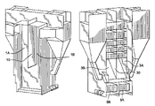
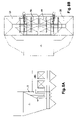
- FIGS. 1 and 2 are perspective views of a first embodiment of a circulating fluidized bed reactor constructed in accordance with the present invention.
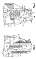
- FIGS. 3 and 4 are perspective views of a first embodiment of a circulating fluidized bed reactor constructed in accordance with the present invention, wherein the reaction chamber thereof and the heat exchanger cage thereof are illustrated as being opened in order to thereby provide an interior view thereof;
- FIGS. 5A to 5C are horizontal cross-sections of the upper portion of a first embodiment of a circulating fluidized bed reactor constructed in accordance with the present invention.
- FIG. 6 is a schematic and partial perspective view of a first embodiment of a circulating fluidized bed reactor constructed in accordance with the present invention.
- FIGS. 7A and 7B are vertical and horizontal cross-sections of a first embodiment of a circulating fluidized bed reactor constructed in accordance with the present invention.
- FIGS. 8A and 8B are also vertical and horizontal cross-sections of a first embodiment of a circulating fluidized bed reactor constructed in accordance with the present invention.
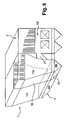
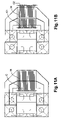
- FIG. 9 is a perspective view of a second embodiment of a circulating fluidized bed reactor constructed in accordance with the present invention.
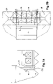
- FIG. 10 is a horizontal cross-section of the upper portion of a second embodiment of a circulating fluidized bed reactor constructed in accordance with the present invention.
- FIGS. 11A to 11C are horizontal cross-sections of the upper portion of a second embodiment of a circulating fluidized bed reactor constructed in accordance with the present invention.
- FIG. 12 is a cross-section of the bottom portion of a second embodiment of a circulating fluidized bed reactor constructed in accordance with the present invention.
- the circulating fluidized bed reactor is of the type similar to that which is described and illustrated in patent document WO 03/038338 that has been filed by the same Assignee as the present patent application.
- this circulating fluidized bed reactor comprises a reaction chamber 1 horizontally bounded by vertical walls, two centrifugal separators 2 A and 2 B and a heat recovery element referred to herein as a heat exchanger cage 3 , which is located behind the reaction chamber 1 .
- This circulating fluidized bed reactor further comprises means for introducing a fluidization gas into the reaction chamber 1 for purposes of maintaining a circulating fluidized bed of particles in this reaction chamber 1 .
- a wind box 4 located under the reaction chamber 1 is utilized for this purpose.
- This circulating fluidized bed reactor also comprises means for transferring from the reaction chamber 1 to the separators 2 A, 2 B the gas, which must be dedusted, means for discharging the particles separated from the gas in the separators 2 A and 2 B, and means for transferring the dust-free gases from the separators 2 A and 2 B to the heat exchanger cage 3 .
- This circulating fluidized bed reactor also comprises two external beds 5 A and 5 B, each of which is designed to receive via a solid particle feed channel the particles leaving each of the separators 2 A and 2 B.
- Each of the external beds 5 A and 5 B has a wall, which is common to the reaction chamber 1 as well.
- the two separators 2 A, 2 B extend laterally, and they each have a vertical wall, which is common with the side wall of the heat exchanger cage 3 .
- this circulating fluidized bed reactor is designed to be supplied with air that is to be used for combustion purposes, but is also capable of being converted in order to be able to operate when supplied with an oxygen-rich mixture for combustion purposes, in an efficient manner and with a minimum number of conversion operations being required in order to achieve this result.
- such an oxygen-rich mixture consists of 70% oxygen and 30% recycled carbon dioxide.
- the reaction chamber 1 comprises a partial internal vertical partition wall 10 that functions to divide the reaction chamber 1 into two subchambers 1 A and 1 B, which communicate with one another and with each also in communication with one of the separators 2 A and 2 B.
- the heat exchanger cage 3 comprises a partial internal vertical partition wall 30 that functions to divide the heat exchanger cage 3 into two subcages 3 A, 3 B, which communicate with one another and with each also in communication with at least one of the separators 2 A and 2 B.
- the partition wall 10 of the reaction chamber 1 extends perpendicularly to the front wall of the reaction chamber 1 and the partition wall 30 of the heat exchanger cage 3 extends parallel to the partition wall 10 of the reaction chamber 1 .
- these partition walls 10 , 30 are arranged in such a manner as to define a cross-section of one of the subchambers, that is, subchamber 1 B and one of the subcages, that is, subcage 3 B in accordance with when the combustion is being conducted with an oxygen feed to the reaction chamber 1 .
- the cross-section of one of said subchambers, that is, subchamber 1 A is between 60 and 65% of the total cross-section of the reaction chamber 1
- the cross-section of the other subchamber, that is, subchamber 1 B is between 35 and 40%.
- the partition walls 10 , 30 extend from the ceiling to the bottom of the reaction chamber 1 and the heat exchanger cage 3 , respectively, and provide for the existence of a free passage in the bottom of the reaction chamber 1 and/or the heat exchanger cage 3 , respectively.
- the partition walls 10 and 30 may provide for the existence of a free passage in the upper portion of the reaction chamber 1 and/or of the heat exchanger cage 3 or the partition walls 10 and 30 may take the form of walls wherein several openings are provided therein, with such openings being distributed or not along their height and being located or not along their entire width.
- the exchangers may be arranged parallel to the front wall of the reaction chamber 1 so that the exchangers pass through the partition wall 30 of the heat exchanger cage 3 in a sealed manner, as shown in FIG. 5A of the Drawings.
- a single row of collectors C is then necessary, with the collectors C being arranged on a side edge of the heat exchanger cage 3 along with steam dedusting apparatus (cleaners) D for cleaning the two subcages 3 A and 3 B and the exchangers.
- the exchangers may also be arranged parallel to the front wall of the reaction chamber 1 so that they do not pass through the partition wall 30 of the heat exchanger cage 3 , as shown in FIG. 5B of the Drawings.
- Two rows of collectors C 1 , C 2 are then necessary, with each being located on one side edge of the heat exchanger cage 3 along with steam dedusting apparatus (cleaners) D for the cleaning of the two subcages 3 A and 3 B and the exchangers.
- the exchangers may also be arranged perpendicular to the front wall of the reaction chamber 1 , as shown in FIG. 5C of the Drawings. Two rows of collectors C are then necessary, with the collectors C being arranged behind the heat exchanger cage 3 along with the steam or infrasonic dedusting apparatus (cleaners), according to the spacing between the exchangers, for purposes of effecting therewith the cleaning of the two subcages 3 A and 3 B and the exchangers.
- cleaning apparatus infrasonic dedusting apparatus
- the wind box 4 is divided into two sub-boxes 4 A, 4 B by a wall 40 , which is located in the same vertical plane as the partition wall 10 of the reaction chamber 1 .
- the wind box 4 may suffice for the wind box 4 to be pre-equipped for subsequent segmentation during the conversion of the circulating fluidized bed reactor.
- a siphon arrangement 6 is located inside the reaction chamber 1 along the length of the wall that is common with the external beds 5 A, 5 B and the reaction chamber 1 .
- the siphon arrangement 6 does not have any specific function to perform other than to provide for the passage of the solids from the external beds 5 A and 5 B to the reaction chamber 1 via the outlet openings 6 A that are arranged along the entire width of the reaction chamber 1 .
- the siphon arrangement 6 may also be installed without departing from the essence of the present invention during assembly of the reactor chamber 1 , when the reaction chamber 1 is being operated with air being employed for purposes of combustion, in order to decrease and simplify the changes that need to be made in order to effect the conversion of the circulating fluidized bed reactor from operation with air for combustion purposes to oxygen for combustion purposes.
- this siphon arrangement 6 may also be installed subsequently without departing from the essence of the present invention during the conversion of the circulating fluidized bed reactor from firing with air to firing with oxygen.
- the open areas of the external beds 5 A, 5 B are oversized in their length, in order to thereby provide free space.
- the vaporization and/or superheat exchangers will in fact need to be added to the external beds 5 A and 5 B for purposes of the conversion of the circulating fluidized bed reactor to enable oxygen and recycled carbon dioxide to be employed for combustion purposes.
- the fuel feed lines are oversized to permit the full passage of the fuel into the subchamber 1 B after such conversion to oxygen and recycled carbon dioxide firing.
- the fuel transport apparatus which must allow for a total injected flow rate into the subchamber 1 B after such conversion to oxygen and recycled carbon dioxide firing.
- the circulating fluidized bed reactor as previously described herein is designed to be operated when air is being employed for combustion purposes. Due to a number of changes, which will now be described, such a circulating fluidized bed reactor is capable of being converted to operate with oxygen and recycled carbon dioxide being utilized for combustion purposes.
- the general principles upon which this conversion is based are to use a single subchamber of the reaction chamber as a firebox or combustion chamber, to use the separator connected to said reaction chamber for the separator's primary function of separating gases and solids, to recover the gases leaving said separator in a subcage of the exchanger cage, to recover the solids leaving said separator in the two external beds connected for the parallel flow of the solids and connected at the outlet of said combustion chamber for transferring the solids, and connected at the outlet of the other subchamber, referred to herein as the cooling chamber, for transferring thereto the fluidization gas, that is, preferably, nitrogen.
- the fluidization gas that is, preferably, nitrogen.
- the method of converting a circulating fluidized bed reactor as described above, to permit it's the circulating fluidized bed reactor's operation with oxygen and recycled carbon dioxide comprises the following conversion steps:
- this siphon arrangement 6 is modified in order to ensure that the outlet of the external beds 5 A and 5 B, there is the required separation of the solids circuit and the fluidization gas circuit of the external beds, the latter preferably being nitrogen, in the following manner:
- siphon arrangement 6 If the siphon arrangement 6 has not been installed in the circulating fluidized bed reactor when the circulating fluidized bed reactor is operating with air before the conversion thereof to oxygen and recycled carbon dioxide firing, a siphon arrangement 6 with its fluidization wind boxes 6 B, having the characteristics to which reference has been had hereinbefore, that is, having outlet openings for solids and outlet openings for gases, will need to be installed in the reaction chamber 1 .
- the wall 40 will need to be so mounted. Only the sub-wind box 4 B, which is located under the subchamber 1 B, is used in this connection and when so used is fluidized with oxygen and/or recycled carbon dioxide.
- a device for intermittent extraction of any material deposits may be provided, without departing from the essence of the present invention, in the bottom of the other sub-wind box 4 A, which is located under the cooling subchamber 1 A.
- Such an extraction device may also be provided, without departing from the essence of the present invention, in the bottom of the cooling subchamber 1 A and close to the siphon arrangement 6 at the outlet of the separator 2 A, such as to be designed to be traversed by the fluidization gases from the external beds 5 A and 5 B.
- the conversion method in accordance with the present invention also comprises the blocking off of all the fuel and secondary combustion air feeds of the cooling subchamber 1 A, whether these feeds are located in the reaction chamber 1 or in the siphon arrangement 6 .
- the secondary combustion air feeds of the combustion subchamber 1 B are equipped with oxygen-rich mixture injection rods.
- Additional vaporization and/or superheat exchangers are installed in the free space of the external beds 5 A, 5 B. After conversion to oxygen and recycled carbon dioxide firing and during such operation with an oxygen-rich mixture, such vaporization and/or superheat exchangers are intended to function to replace the internal heat exchanger area of the cooling subchamber 1 A which is no longer used. Such vaporization and/or superheat exchangers are made to discharge into the shield circuits in order to thereby avoid the need for a circulating pump.
- the initial flue gas circuit Downstream of the heat exchanger cage 3 , the initial flue gas circuit is used to process the gases that are discharged from the external beds 5 A and 5 B.
- a separate circuit is added after conversion to oxygen and recycled carbon dioxide firing in order to thereby process the flue gases containing carbon dioxide and steam that originate from the oxygen-rich fuel combustion circuit.
- This added separate circuit consists of ducts, gas-gas heat exchangers, filtration devices, fans and condensers that are designed to be operative to function as a carbon dioxide processing train before the compression of the carbon dioxide for transport purposes.
- the circulating fluidized bed reactor is of a similar type as that described in patent document WO 2004/036118 filed by the same Assignee as the present patent application.
- a circulating fluidized bed reactor may comprise a reaction chamber horizontally bounded by vertical walls, n centrifugal separators that are provided with flue gas outlet ducts connecting each pair of such separators to a rear heat exchanger cage and an exchanger cage located behind the reaction chamber 1 , and with the reaction chamber 1 having each of it's the reaction chamber's vertical or side walls positioned so as to be common with a vertical or side wall of a set of n/2 separators.
- This modular circulating fluidized bed reactor in accordance with the present invention comprises a reaction chamber 1 , which is horizontally bounded by vertical walls, two to six separators depending on the size of the circulating fluidized bed reactor, the embodiment of the present invention, which is being described here has four centrifugal separators 2 A to 2 D, and a heat recovery element, referred to herin as a heat exchanger cage 3 that is located behind the reaction chamber 1 .
- This circulating fluidized bed reactor further includes means for introducing a fluidization gas into the reaction chamber 1 and for maintaining a circulating fluidized bed of particles in this reaction chamber 1 .
- This circulating fluidized bed reactor also includes means for transferring the gas that must be dedusted from the reactor chamber 1 to the separators 2 , means for discharging the particles separated from the separators 2 , and means for transferring the dust-free gases from the separators 2 to the heat exchanger cage 3 .
- This circulating fluidized bed reactor may also include, without departing from the essence of the present invention, two to six beds, with the specific embodiment that is being described here having four external beds 5 A to 5 D, each of which is designed to receive particles leaving each of a corresponding separator via a solid particle feed channel, and each possibly having a common wall with the reaction chamber 1 .
- Each of the vertical walls or side walls of the reaction chamber 1 may be common with a vertical or side wall of a pair of separators.
- such a circulating fluidized bed reactor which is designed to be supplied with air for combustion purposes is capable of being converted so as to be able to be made to operate when firing an oxygen-rich mixture, in an efficient manner and with a minimum number of conversion operations being required in order to accomplish this result.
- such a oxygen-rich mixture consists of 70% oxygen and 30% recycled carbon dioxide.
- the reaction chamber 1 includes at least one partial internal vertical partition wall 10 that is operative to form two subchambers 1 A and 1 B, which communicate with one another, and which also each communicate with side separators.
- the heat exchanger cage 3 includes a partial internal vertical partition wall 30 that is operative to form two subcages 3 A, 3 B, which communicate with each other, and which also each communicate with the separators.
- the partition wall 10 of the reaction chamber extends parallel to the front wall S 1 of the reaction chamber 1
- the partition wall 30 of the heat exchanger cage e extends parallel to the partition wall 10 of the reaction chamber 1 .
- the partition walls 10 , 30 are so arranged such as to thereby define a cross-section of the subchamber 1 B, and one of the subcages, that is, subcage 3 B when the mode of operation involves oxygen being supplied to the reaction chamber 1 .
- the cross-section of the sunvhamber 1 A is between 60 and 65% of the total cross-section of the reaction chamber 1 , while the cross-section of the subchamber 1 B is between 35 and 40%.
- the cross-section of the subcahe 3 A is between 60 and 65% of the total cross-section of the heat exchanger cage 3 , while the cross-section of the subcage 3 B is between 35 and 40%.
- the partition walls 10 , 30 extend from the ceiling to the bottom of the reaction chamber 1 and heat exchanger bed 3 , respectively, so as to thereby provide a free passage in the bottom of the reaction chamber 1 and/or of the heat exchanger cage 3 .
- the partition walls 10 , 30 may also be made to provide a free passage in the upper portion of the reaction chamber 1 and of the heat exchanger cage 3 or the partition walls 10 , 30 may take the form of walls wherein several openings, are or are not distributed along their height and are or are not arranged along their entire width.
- the exchangers may be arranged so as to extend perpendicular to the front wall S 1 of the reaction chamber 1 and may be made to pass through the partition wall 30 of the heat exchanger cage 3 in a sealed manner, as illustrated in FIG. 11A of the Drawings.
- a single row of collectors C is then necessary, and such collectors C can be arranged on either the front edge of or behind the heat exchanger cage 3 .
- the exchangers may also be arranged so as to extend perpendicular to the front wall of the reaction chamber 1 and not be made to pass through the partition wall 30 of the heat exchanger cage 3 in a sealed manner, as illustrated in FIG. 11B of the Drawings. In such a case, two rows of collectors C 1 and C 2 are then necessary, with such collectors C being arranged on the front and back edges of the heat exchanger cage 3 .
- the exchangers may also be arranged so as to extend parallel to the front wall S 1 of the reaction chamber 1 such that the exchangers do not pass through the partition wall 30 of the heat exchanger cage 3 , as illustrated in FIG. 11C of the Drawings. In such a case, two rows of collectors C 1 , C 2 are then necessary, with each being arranged on one side edge of the heat exchanger cage 3 .
- the lower portion of the reaction chamber 1 may be of the type wherein an internal wall is formed in an upside-down V and comprises two fluidization hearths and two parallel wind boxes 4 ′ and 4 ′′, that are clearly visible in FIG. 9 of the Drawings.
- Each of the boxes 4 ′ and 4 ′′ in turn is divided into two sub-boxes by a wall that is located in the same vertical plane as the partition wall 10 of the reaction chamber 1 .
- wind boxes 4 ′ and 4 ′′ may suffice for the wind boxes 4 ′ and 4 ′′ to be pre-equipped so as to be capable of subsequently being segmented when the circulating fluidized bed reactor is being converted from air firing to oxygen and recycled carbon dioxide firing.
- two lateral siphon arrangements 6 ′ and 6 ′′ may be arranged fully or partially in the reaction chamber 1 on the length of the wall closest to the external beds 5 A to 5 D or possibly can be made to be common with the lateral external beds 5 A to 5 D of the reaction chamber 1 .
- the siphon arrangements 6 ′ and 6 ′′ Prior to conversion, that is, when being operated with air firing, do not perform any specific function other than to ensure the passage of the solids from the external beds 5 A to 5 D to the reaction chamber 1 via outlet openings suitably arranged for this purpose along the entire length of the reaction chamber 1 .
- the siphon arrangements 6 ′ and 6 ′′ can be installed upon the assembly of the circulatimg fluidized bed reactor in order to thereby decrease and simplify the modifications required during the conversion of the circulating fluidized bed reactor from air firing to oxygen and recycled carbon dioxide firing.
- siphon arrangements 6 ′ and 6 ′′ may be equally well installed subsequently during the conversion of the circulating fluidized bed reactor from air firing to oxygen and recycled carbon dioxide firing.
- the open areas of the external beds 5 A to 5 D are oversized in their length in order to thereby provide a free space. As described hereinafter, vaporization and/or superheat exchangers will in fact have to be added in these external beds 5 A to 5 D in order to allow for the operation with oxygen and with recycled carbon dioxide.
- the two upper flue gas outlet ducts connecting each pair of separators 2 A, 2 B and 2 C, 2 D to the back exchanger cage are equipped with a vertical and partial partition wall 7 , 8 of which their back edge is in the same plane as that of the partition wall 30 of the heat exchanger cage 3 .
- the fuel feed lines are oversized in order to thereby permit the full passage of the fuel after conversion in the combustion subchamber 1 B.
- a reactor as previously described is designed to operate with air. Thanks to a number of changes which are now described, it can be converted so as to operate within an oxygen-rich mixture.
- the general principle of this conversion is to use a single subchamber of the reaction chamber as a firebox or combustion subchamber, to use the two separators connected to it in their primary gas and solids separation function, to recover the gases leaving these separators in a subcage of the exchanger cage, to recover the solids leaving these separators in the two corresponding external beds connected to the other external beds to be traversed in parallel by the solids each with its adjacent bed and connected at the outlet of said combustion chamber for transferring the solids thereto and connected at the outlet of the other subchamber, called the cooling subchamber, for transferring thereto the fluidization gas, that is preferably nitrogen.
- the method for converting a circulating fluidized bed reactor as described above, in order to permit its operation with oxygen and recycle carbon dioxide comprises the following conversion steps:
- siphon arrangements 6 ′ and 6 ′′ have already been installed on the reactor before conversion, these siphon arrangements are modified by the following operations, in order to ensure at the outlet of the external beds, the separation of the solids circuit and the fluidization gas circuit of the external beds, that is preferably nitrogen:
- siphon arrangement If the siphon arrangement has not been installed on the reactor operating with air before conversion, a siphon arrangement with its wind boxes having the above characteristics, that is outlet openings for solids and outlet openings for gases according to the subchamber, is installed in the reaction chamber.
- the partition walls 7 , 8 of the flue ducts are blocked at their end O in the cyclones so that the sub-lines supplying the subcage 3 B may retain part of the flue gases leaving the back cyclones 2 B, 2 D.
- a device for intermittent extraction of any deposits can be provided in the bottom of the cooling subchamber 1 A and the other sub-boxes located under the cooling subchamber 1 A.
- Such an extraction device may also be provided close to the siphon arrangement at the outlet of the separators 2 A and 2 C designed to be traversed by the fluidization gases of the external beds.
- the conversion method also comprises the blocking of all the fuel and secondary combustion air feeds of the cooling subchamber 1 A, whether these feeds are located in the reaction chamber or in the siphon arrangement.
- the secondary combustion air feeds of the combustion subchamber 1 B are equipped with oxygen-rich mixture injection rods.
- Additional vaporization. and/or superheat exchangers are installed in the free space of the external beds 5 A, 5 B, 5 C, 5 D. After conversion and during operation with an oxygen-rich mixture, these exchangers replace the internal heat exchange area of cooling subchamber 1 A which is no longer used. These exchangers can discharge into the shield circuits to avoid the need for a circulating pump.
- the initial flue gas circuit Downstream of the exchanger cage 3 , the initial flue gas circuit is used to process the gases discharged from the external beds.
- a separate circuit is added to process the flue gases containing carbon dioxide and steam and originating from the oxygen-rich fuel combustion circuit. This added circuit comprises ducts, gas-gas heat exchangers, filtration devices, fans and condensers toward a carbon dioxide processing train before compression for transport.
Landscapes
- Engineering & Computer Science (AREA)
- Chemical & Material Sciences (AREA)
- Combustion & Propulsion (AREA)
- Mechanical Engineering (AREA)
- General Engineering & Computer Science (AREA)
- Devices And Processes Conducted In The Presence Of Fluids And Solid Particles (AREA)
- Fluidized-Bed Combustion And Resonant Combustion (AREA)
- Organic Low-Molecular-Weight Compounds And Preparation Thereof (AREA)
Applications Claiming Priority (2)
| Application Number | Priority Date | Filing Date | Title |
|---|---|---|---|
| FR0553050A FR2891893B1 (fr) | 2005-10-07 | 2005-10-07 | Reacteur a lit fluidise circulant a procede de combustion convertible |
| FR0553050 | 2005-10-07 |
Publications (2)
| Publication Number | Publication Date |
|---|---|
| US20070079773A1 US20070079773A1 (en) | 2007-04-12 |
| US7520249B2 true US7520249B2 (en) | 2009-04-21 |
Family
ID=36676512
Family Applications (1)
| Application Number | Title | Priority Date | Filing Date |
|---|---|---|---|
| US11/541,271 Expired - Fee Related US7520249B2 (en) | 2005-10-07 | 2006-09-29 | Circulating fluidized bed reactor with a convertible combustion method |
Country Status (6)
| Country | Link |
|---|---|
| US (1) | US7520249B2 (fr) |
| EP (1) | EP1772670B1 (fr) |
| CN (1) | CN1973988B (fr) |
| DE (1) | DE602006000936T2 (fr) |
| ES (1) | ES2306400T3 (fr) |
| FR (1) | FR2891893B1 (fr) |
Cited By (6)
| Publication number | Priority date | Publication date | Assignee | Title |
|---|---|---|---|---|
| US20090178779A1 (en) * | 2008-01-14 | 2009-07-16 | White William J | Heat exchanger |
| US20100101564A1 (en) * | 2008-10-24 | 2010-04-29 | Iannacchione Steven P | Shop-assembled solar receiver heat exchanger |
| US20100216621A1 (en) * | 2007-10-08 | 2010-08-26 | Foster Wheeler Energia Oy | Centrifugal Separator Assembly |
| US20120103584A1 (en) * | 2009-06-24 | 2012-05-03 | Institute Of Engineering Thermophysics, Chinese Academy Of Sciences | Water-cooling u-valve |
| EP2884169A1 (fr) * | 2013-12-16 | 2015-06-17 | Doosan Lentjes GmbH | Appareil à lit fluidisé |
| EP4098943A1 (fr) * | 2021-06-02 | 2022-12-07 | Doosan Lentjes GmbH | Installation d'incinération |
Families Citing this family (11)
| Publication number | Priority date | Publication date | Assignee | Title |
|---|---|---|---|---|
| FR2845620B1 (fr) * | 2002-10-14 | 2007-11-30 | Alstom Switzerland Ltd | Reacteur a lit fluidise circulant avec separateur et gaine d'acceleration integree |
| US8196532B2 (en) * | 2008-02-27 | 2012-06-12 | Andrus Jr Herbert E | Air-fired CO2 capture ready circulating fluidized bed heat generation with a reactor subsystem |
| CN101514811B (zh) * | 2009-03-17 | 2011-12-07 | 西安交通大学 | 无夹廊角管全膜式壁循环流化床锅炉 |
| FI124762B (fi) * | 2009-04-09 | 2015-01-15 | Foster Wheeler Energia Oy | Kiertoleijupetikattila |
| CN102466223B (zh) | 2010-10-29 | 2014-08-20 | 中国科学院工程热物理研究所 | 一种循环流化床锅炉 |
| CN102425965B (zh) * | 2011-12-01 | 2013-08-14 | 兰州节能环保工程有限责任公司 | 粉粒状固体物料板式换热器 |
| CZ305044B6 (cs) * | 2013-08-20 | 2015-04-08 | Ústav chemických procesů AV ČR, v.v.i. | Zařízení pro fluidní spalování pevných paliv či suspenzí |
| US10145626B2 (en) * | 2013-11-15 | 2018-12-04 | General Electric Technology Gmbh | Internally stiffened extended service heat recovery steam generator apparatus |
| FI126040B (en) * | 2014-07-09 | 2016-06-15 | Amec Foster Wheeler En Oy | Particle separator and fluidized bed reactor that can be connected to a fluidized bed reactor |
| FI127698B (en) * | 2016-04-04 | 2018-12-14 | Amec Foster Wheeler Energia Oy | CIRCULAR FLOID BOILER AND METHOD FOR INSTALLING CIRCULAR FLOOR BOILER |
| US10591155B2 (en) * | 2016-08-25 | 2020-03-17 | Doosan Lentjes Gmbh | Circulating fluidized bed apparatus |
Citations (10)
| Publication number | Priority date | Publication date | Assignee | Title |
|---|---|---|---|---|
| US3893426A (en) * | 1974-03-25 | 1975-07-08 | Foster Wheeler Corp | Heat exchanger utilizing adjoining fluidized beds |
| US4542115A (en) * | 1981-08-17 | 1985-09-17 | Degussa Aktiengesellschaft | Zeolite granulate, process for its production |
| US4761131A (en) * | 1987-04-27 | 1988-08-02 | Foster Wheeler Corporation | Fluidized bed flyash reinjection system |
| US5181481A (en) * | 1991-03-25 | 1993-01-26 | Foster Wheeler Energy Corporation | Fluidized bed combustion system and method having multiple furnace sections |
| US20010025702A1 (en) * | 1996-06-27 | 2001-10-04 | Timo Hyppanen | Method and apparatus for controlling heat transfer from solids particles in a fluidized bed |
| US6505567B1 (en) | 2001-11-26 | 2003-01-14 | Alstom (Switzerland) Ltd | Oxygen fired circulating fluidized bed steam generator |
| WO2003038338A1 (fr) | 2001-10-30 | 2003-05-08 | Alstom (Switzerland) Ltd | Dispositif de reacteur a lit fluidise circulant |
| WO2004036118A2 (fr) | 2002-10-14 | 2004-04-29 | Alstom (Switzerland) Ltd | Reacteur a lit fluidise circulant avec separateur et gaine d'acceleration integree |
| US6938780B2 (en) * | 2001-10-30 | 2005-09-06 | Alstom (Switzerland) Ltd. | Centrifugal separator in particular for fluidized bed reactor device |
| US20080000403A1 (en) * | 2004-05-28 | 2008-01-03 | Alstom Technology Ltd | Fluidized-Bed Device With Oxygen-Enriched Oxidizer |
-
2005
- 2005-10-07 FR FR0553050A patent/FR2891893B1/fr not_active Expired - Fee Related
-
2006
- 2006-09-28 EP EP06300996A patent/EP1772670B1/fr not_active Not-in-force
- 2006-09-28 DE DE602006000936T patent/DE602006000936T2/de active Active
- 2006-09-28 ES ES06300996T patent/ES2306400T3/es active Active
- 2006-09-29 US US11/541,271 patent/US7520249B2/en not_active Expired - Fee Related
- 2006-10-06 CN CN2006101605100A patent/CN1973988B/zh not_active Expired - Fee Related
Patent Citations (11)
| Publication number | Priority date | Publication date | Assignee | Title |
|---|---|---|---|---|
| US3893426A (en) * | 1974-03-25 | 1975-07-08 | Foster Wheeler Corp | Heat exchanger utilizing adjoining fluidized beds |
| US4542115A (en) * | 1981-08-17 | 1985-09-17 | Degussa Aktiengesellschaft | Zeolite granulate, process for its production |
| US4761131A (en) * | 1987-04-27 | 1988-08-02 | Foster Wheeler Corporation | Fluidized bed flyash reinjection system |
| US5181481A (en) * | 1991-03-25 | 1993-01-26 | Foster Wheeler Energy Corporation | Fluidized bed combustion system and method having multiple furnace sections |
| US20010025702A1 (en) * | 1996-06-27 | 2001-10-04 | Timo Hyppanen | Method and apparatus for controlling heat transfer from solids particles in a fluidized bed |
| WO2003038338A1 (fr) | 2001-10-30 | 2003-05-08 | Alstom (Switzerland) Ltd | Dispositif de reacteur a lit fluidise circulant |
| US20040065273A1 (en) * | 2001-10-30 | 2004-04-08 | Daniel Baglione | Circulating fluidized bed reactor device |
| US6938780B2 (en) * | 2001-10-30 | 2005-09-06 | Alstom (Switzerland) Ltd. | Centrifugal separator in particular for fluidized bed reactor device |
| US6505567B1 (en) | 2001-11-26 | 2003-01-14 | Alstom (Switzerland) Ltd | Oxygen fired circulating fluidized bed steam generator |
| WO2004036118A2 (fr) | 2002-10-14 | 2004-04-29 | Alstom (Switzerland) Ltd | Reacteur a lit fluidise circulant avec separateur et gaine d'acceleration integree |
| US20080000403A1 (en) * | 2004-05-28 | 2008-01-03 | Alstom Technology Ltd | Fluidized-Bed Device With Oxygen-Enriched Oxidizer |
Cited By (10)
| Publication number | Priority date | Publication date | Assignee | Title |
|---|---|---|---|---|
| US20100216621A1 (en) * | 2007-10-08 | 2010-08-26 | Foster Wheeler Energia Oy | Centrifugal Separator Assembly |
| US8506665B2 (en) | 2007-10-08 | 2013-08-13 | Foster Wheeler Energia Oy | Centrifugal separator assembly |
| US20090178779A1 (en) * | 2008-01-14 | 2009-07-16 | White William J | Heat exchanger |
| US20100101564A1 (en) * | 2008-10-24 | 2010-04-29 | Iannacchione Steven P | Shop-assembled solar receiver heat exchanger |
| US9194609B2 (en) | 2008-10-24 | 2015-11-24 | The Babcock & Wilcox Company | Shop-assembled solar receiver heat exchanger |
| US20120103584A1 (en) * | 2009-06-24 | 2012-05-03 | Institute Of Engineering Thermophysics, Chinese Academy Of Sciences | Water-cooling u-valve |
| US9476585B2 (en) * | 2009-06-24 | 2016-10-25 | Institute Of Engineering Thermophysics, Chinese Academy Of Sciences | Water-cooling U-valve |
| EP2884169A1 (fr) * | 2013-12-16 | 2015-06-17 | Doosan Lentjes GmbH | Appareil à lit fluidisé |
| WO2015090637A1 (fr) * | 2013-12-16 | 2015-06-25 | Doosan Lentjes Gmbh | Appareil à lit fluidisé |
| EP4098943A1 (fr) * | 2021-06-02 | 2022-12-07 | Doosan Lentjes GmbH | Installation d'incinération |
Also Published As
| Publication number | Publication date |
|---|---|
| EP1772670B1 (fr) | 2008-04-16 |
| FR2891893A1 (fr) | 2007-04-13 |
| ES2306400T3 (es) | 2008-11-01 |
| DE602006000936T2 (de) | 2009-06-04 |
| EP1772670A1 (fr) | 2007-04-11 |
| DE602006000936D1 (de) | 2008-05-29 |
| CN1973988A (zh) | 2007-06-06 |
| US20070079773A1 (en) | 2007-04-12 |
| FR2891893B1 (fr) | 2007-12-21 |
| CN1973988B (zh) | 2012-07-04 |
Similar Documents
| Publication | Publication Date | Title |
|---|---|---|
| US7520249B2 (en) | Circulating fluidized bed reactor with a convertible combustion method | |
| US8230796B2 (en) | Air-fired CO2 capture ready circulating fluidized bed steam generators | |
| CN103672871B (zh) | 加压有氧燃烧功率锅炉和功率设备以及操作其的方法 | |
| US9651244B2 (en) | Method of operating an oxycombustion circulating fluidized bed boiler | |
| JP5331648B2 (ja) | 微粉炭ボイラの改造方法 | |
| CZ287126B6 (en) | Circulating fluidized bed reactor | |
| KR100289287B1 (ko) | 유동층반응기시스템및그작동방법 | |
| US5435820A (en) | Water/steam-cooled U-beam impact type particle separator | |
| JPH0694922B2 (ja) | 通路分離装置を備えた流動床反応器 | |
| CN101981376B (zh) | 使用用于燃烧含碳物料的设备的方法及相关设备 | |
| US7987993B2 (en) | Solid separator especially for a combustion facility | |
| KR101377245B1 (ko) | 유동층 반응기 장치 | |
| CN101228395B (zh) | 模块式流化床反应器 | |
| US11835298B2 (en) | Heat exchanger for a loopseal of a circulating fluidized bed boiler and a circulating fluidized bed boiler |
Legal Events
| Date | Code | Title | Description |
|---|---|---|---|
| AS | Assignment |
Owner name: ALSTOM TECHNOLOGY LTD, SWITZERLAND Free format text: ASSIGNMENT OF ASSIGNORS INTEREST;ASSIGNORS:MORIN, JEAN-XAVIER;BEAL, CORINNE;SURANITI, SILVESTRE;AND OTHERS;REEL/FRAME:018374/0979;SIGNING DATES FROM 20060920 TO 20060927 |
|
| STCF | Information on status: patent grant |
Free format text: PATENTED CASE |
|
| FPAY | Fee payment |
Year of fee payment: 4 |
|
| AS | Assignment |
Owner name: GENERAL ELECTRIC TECHNOLOGY GMBH, SWITZERLAND Free format text: CHANGE OF NAME;ASSIGNOR:ALSTOM TECHNOLOGY LTD;REEL/FRAME:039714/0578 Effective date: 20151102 |
|
| FPAY | Fee payment |
Year of fee payment: 8 |
|
| FEPP | Fee payment procedure |
Free format text: MAINTENANCE FEE REMINDER MAILED (ORIGINAL EVENT CODE: REM.); ENTITY STATUS OF PATENT OWNER: LARGE ENTITY |
|
| LAPS | Lapse for failure to pay maintenance fees |
Free format text: PATENT EXPIRED FOR FAILURE TO PAY MAINTENANCE FEES (ORIGINAL EVENT CODE: EXP.); ENTITY STATUS OF PATENT OWNER: LARGE ENTITY |
|
| STCH | Information on status: patent discontinuation |
Free format text: PATENT EXPIRED DUE TO NONPAYMENT OF MAINTENANCE FEES UNDER 37 CFR 1.362 |
|
| FP | Lapsed due to failure to pay maintenance fee |
Effective date: 20210421 |