US752011A - A coepoeation - Google Patents
A coepoeation Download PDFInfo
- Publication number
- US752011A US752011A US752011DA US752011A US 752011 A US752011 A US 752011A US 752011D A US752011D A US 752011DA US 752011 A US752011 A US 752011A
- Authority
- US
- United States
- Prior art keywords
- steam
- piston
- arm
- box
- valve
- Prior art date
- Legal status (The legal status is an assumption and is not a legal conclusion. Google has not performed a legal analysis and makes no representation as to the accuracy of the status listed.)
- Expired - Lifetime
Links
- 238000010276 construction Methods 0.000 description 6
- QVGXLLKOCUKJST-UHFFFAOYSA-N atomic oxygen Chemical compound [O] QVGXLLKOCUKJST-UHFFFAOYSA-N 0.000 description 5
- 239000001301 oxygen Substances 0.000 description 5
- 229910052760 oxygen Inorganic materials 0.000 description 5
- 238000002485 combustion reaction Methods 0.000 description 3
- 239000000446 fuel Substances 0.000 description 3
- 230000001105 regulatory effect Effects 0.000 description 3
- 239000004020 conductor Substances 0.000 description 2
- 239000007789 gas Substances 0.000 description 2
- 210000003141 lower extremity Anatomy 0.000 description 2
- 239000000779 smoke Substances 0.000 description 2
- 239000007921 spray Substances 0.000 description 2
- 239000002699 waste material Substances 0.000 description 2
- 241001052209 Cylinder Species 0.000 description 1
- 101100001674 Emericella variicolor andI gene Proteins 0.000 description 1
- 235000000434 Melocanna baccifera Nutrition 0.000 description 1
- 241001497770 Melocanna baccifera Species 0.000 description 1
- 230000002730 additional effect Effects 0.000 description 1
- 238000004891 communication Methods 0.000 description 1
- 230000001276 controlling effect Effects 0.000 description 1
- 210000003414 extremity Anatomy 0.000 description 1
- 238000010304 firing Methods 0.000 description 1
- 238000010438 heat treatment Methods 0.000 description 1
- 238000002347 injection Methods 0.000 description 1
- 239000007924 injection Substances 0.000 description 1
- 238000004519 manufacturing process Methods 0.000 description 1
- 238000000034 method Methods 0.000 description 1
- 230000000979 retarding effect Effects 0.000 description 1
Images


Classifications
-
- F—MECHANICAL ENGINEERING; LIGHTING; HEATING; WEAPONS; BLASTING
- F23—COMBUSTION APPARATUS; COMBUSTION PROCESSES
- F23H—GRATES; CLEANING OR RAKING GRATES
- F23H3/00—Grates with hollow bars
- F23H3/02—Grates with hollow bars internally cooled
-
- F—MECHANICAL ENGINEERING; LIGHTING; HEATING; WEAPONS; BLASTING
- F23—COMBUSTION APPARATUS; COMBUSTION PROCESSES
- F23N—REGULATING OR CONTROLLING COMBUSTION
- F23N3/00—Regulating air supply or draught
- F23N3/02—Regulating draught by direct pressure operation of single valves or dampers
Definitions
- My invention relates to devices for controlling the draft for furnaces and for supplying additional oxygen to the re to assist in combustion and to secure more efficient results from the fuel with less smoke and waste, and I5 I accomplish this by automatically regulating the draft and the supply of oxygen through steam, as hereinafter more particularly described.
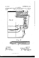
- Figure 1 is a front elevation showing the lower portion of a boiler-front and the automatic draft-regutor in position thereon.
- Fig. 2 is a section on the line a of Fig. 1.
- Fig. 3 is a section view of one of the steam-jets, showing the construction to spray the steam over the surface of the fire-box.
- Fig. 4 is a section view of the oil-cylinder and connections, showing the construction ofthe parts.
- Fig. 5 is a section view of the arm operated by the Ere-box door, showing the joint therein for permitting it to be turned up out of the way.
- the cylinder 31 is filled with oil and also has a pipe upon one side, as 32, leading the oil from a point above the cylinder to a point below the cylinder.
- This pipe has a check-valve 33 therein, which permits the oil to pass from above the piston to the portion below the piston whenever the piston is raised, as above described,lbut preventing the oil from returning by theV same pipey whenever the weights 24 push the piston down and compress the oil. in the lower portionl of the cylinder.
- a second. pipe also con necting the portion of the cylinder above the" pistonwith the portion below the piston, being number 341, and in this ⁇ pipe I have placed the adjustable valve 35, which may be opened.
- the time in which the pistoncan descend may be regulated by adjusting the valve 35,v so.. as. to makethe length of time required for the piston tode.- scend to its initial position to be. longer or shorter, as desired, and. as the. leverof the valve 21 cannot close said valve until the pis.- ton has again descended the said valve 21 refmains open until the piston again. reaches-its initial position, thus giving the operatormeans for adjusting the device to supply steamtothe tire-box any desired length of time-.after each fresh lot of fuell is put therein..
- an in- 50 jector comprising a tube provided with an external contracted end, a slot in said end of the tube, andthe internal bore of. the tube having a cone-shaped opening leading into said slot.
Landscapes
- Engineering & Computer Science (AREA)
- Chemical & Material Sciences (AREA)
- Combustion & Propulsion (AREA)
- Mechanical Engineering (AREA)
- General Engineering & Computer Science (AREA)
- Furnace Housings, Linings, Walls, And Ceilings (AREA)
Description
A. H. THAYBR.
` PATENIED FEL 9, 1904.
'N0 MODEL.
APPLIUATIGN FILED JAN'4 22, 1903.
3 SHEETS-SHEET 1.
Hill-IIN! muli! PATENTBD FEB. 9, 1904.
A Y A. vH. THAYER. AUTOMATIC DRAFT REGULATOR AND SMQKE PREVENTBR FOR vPURNAGES.
APPLIOATION FILED JAN. 22. 1903.
3 SHEETS-SHEET 2` X0 MODEL.
Illlllll'vllllllllllll y IN V E N TO R 7/llv 'IIIIIIIIIllllllllllllllulll'l WITNESSES:
No. 752,011. 1 PATENTBDPBB. s, 1904. A. H. THAYER.
AUTOMATIC DRAFT REGULATOR AND SMOKE PRBVBNTBR F011 PURNAGES.
APPLIUATIGN FILED JAN. 22, 1903.
/////////m/// 75. 4L fa A \/31 'f5 Zi I l 7 I f ff `WITNESSES: :NVENTOR: @6o/ww @407mm gf/ UNITED STATES Patented February 9, 1904.
VPATENT OEEICE.
.CUSHION SPRING COMPANY, OF OF MICHIGAN.
AUTOMATIC DRAFT-REGULATOR AND JACKSON, MICHIGAN, A CORPORATION SMOKE-PREVENTER FOR FURNACES.
SPECIFICATION forming part of Letters Patent No. 752,011, dated. February 9, 1904.
Appncainn ma Jaimy z2, 1903.
To all whomrt't may concern,.-
Be it known that I, ADELBERT H. THAYER, a citizen of the United States, residing at the city of Jackson, in the county of Jackson and State of Michigan, have invented certain new and useful Improvements in Automatic Draft- Regulators and Smoke-Preventers for Fur.- naces, of which the following is a specification.
My invention relates to devices for controlling the draft for furnaces and for supplying additional oxygen to the re to assist in combustion and to secure more efficient results from the fuel with less smoke and waste, and I5 I accomplish this by automatically regulating the draft and the supply of oxygen through steam, as hereinafter more particularly described.
. The special advantages of my improvements 2O are, first, the air supplied to the combustionchamber is warmed before entering the firebox, and hence aids the combustion without lowering the temperature; second, the improved nozzle which I employ sprays the steam over the surface of the fire more evenly than those heretofore employed; third, the automatic device for opening the draft and steam jets and for closing them makes the operation of the device effrcient irrespective of whether the fireman is careless or not, other benefits and advantages being apparent from the following description.
In the drawings forming part of this speciiication, and in which like numerals of refererence refer to similar parts, Figure 1 is a front elevation showing the lower portion of a boiler-front and the automatic draft-regutor in position thereon. Fig. 2 is a section on the line a of Fig. 1. Fig. 3 is a section view of one of the steam-jets, showing the construction to spray the steam over the surface of the fire-box. Fig. 4 is a section view of the oil-cylinder and connections, showing the construction ofthe parts. Fig. 5 is a section view of the arm operated by the Ere-box door, showing the joint therein for permitting it to be turned up out of the way.
In the drawings forming part of this speci- Serial No 140,125. (No model.)
ication, 1 represents the lower portion of a boiler-front, `and 2 2 represent the fire-box doors through which fuel is fed to the lire. The doors 3 3 open into the ash-pit. y I have attached to the said boiler-front for convenience the plate 4, which is substantially rectangular, and to this are attached most of the parts forming my device. The upright shaft 5 is mounted in bearings formed in the brackets 40 A0, attached to saidplatei, and has at its lower extremity a bevel gear-wheel. At its middle portion an arm 7 extends out horizontally into the path of the right-hand firebox door and terminates in a fork, between the prongs of which I have supported the wheel 9. lThis wheel 9 at the end of the arm presses against the door whenever it is opened and the arm is moved outwardly in a circular direction, revolving the shaft 5. At a middle point in said arm 7 I have made a knucklejoint 8, which permits the extremity to be raised, as shown in dotted lines, Fig. 1, for convenience in disconnecting the said arm from operation with said door. The horizontal shaft I1 is mounted in bearings in the brackets 12 12 and supports the bevel gearwheel 10 in mesh with the gear-wheel 6 aforesaid. At the right-hand end of said shaft 11 I have attached a double arm 13, one end, 14, thereof being connected with the pistonrod 16 by means of the rod 15 at the joint 17, and the other end, 18, of said double arm being connected by means of the rod 19 with the lever 20., operating the valve 21 inthe steampipe 22. By this construction whenever the fire-box door is opened to renew the fire the arm 7 is turned outwardly, revolving the shaft 5, to which it is attached, andV this in turn revolves the shaft 11 through the bevel gearwheels, and when this shaft is revolved the double arm pulls down the lever20, operating the valve 21 aforesaid, permittingy steam to pass through said valve and vinto the lirebox through the steam-jets 38 3838 38, connected with said steam-pipe at 37 37 37 37, arranged, preferably, with two over each lirebox door. At the same time the other end 14 of said double arm 1.3 raises the pistonrod 16 and the piston 23 and the weights 24, mountedV upon the upper end' of said pistonrod. To regulate the speed with which the valve 21 is closed, the cylinder 31 is filled with oil and also has a pipe upon one side, as 32, leading the oil from a point above the cylinder to a point below the cylinder. This pipe has a check-valve 33 therein, which permits the oil to pass from above the piston to the portion below the piston whenever the piston is raised, as above described,lbut preventing the oil from returning by theV same pipey whenever the weights 24 push the piston down and compress the oil. in the lower portionl of the cylinder. At the other side ofthe cylinder I have arranged a second. pipe, also con necting the portion of the cylinder above the" pistonwith the portion below the piston, being number 341, and in this` pipe I have placed the adjustable valve 35, which may be opened. to any desired extent to permit the oilt to return from below the piston to. the portion` above the piston whenever the pressure of the piston and weights force the oil from below the piston through thisvalve to theV portion above the piston. By this means. the time in which the pistoncan descend may be regulated by adjusting the valve 35,v so.. as. to makethe length of time required for the piston tode.- scend to its initial position to be. longer or shorter, as desired, and. as the. leverof the valve 21 cannot close said valve until the pis.- ton has again descended the said valve 21 refmains open until the piston again. reaches-its initial position, thus giving the operatormeans for adjusting the device to supply steamtothe tire-box any desired length of time-.after each fresh lot of fuell is put therein..
At the left-hand end of the shaft 11 I' have attached the arm 25, which is. connected by means of a connecting-rod'. 28; with. the. rod 26, attached to the dampers. 27, arranged, as shown, in the dead-plate with one damper bef neath each fire-box door.. By this. construction whenever the firebox door isA opened by means of the arm 7 and the shafts 5. and 11 the said dampers 27 are opened and remain open` as long as the pistonremainselevatedlin the said cylinder, as aforesaid. As the cylin der descends the shaft 11' gradually returns to its initial position and the dampers127f are gradually closed. About these dampersI have placed a box 29, which haspipesextending-to the rear portion of the ash-ptunderneatht-he rebox,with openingsatthe rear ends thereof through which air is drawn intosaid pipesand 'through said damperstosaidiire-box.. The
object of said pipes and said box tosuperheat the air entering theiire-box through said dampers by forcing it to pass. backward through said ash-pit and forwardL again with in. said pipes, thus doubly heating said before it enters the hre-box, greatly increasing the combustion in said fire-box, andI preventing the boiler and fire from being cooled off or deadened, as would occur if the air. were admitted' direct to, said fire-box.
In the construction of the jets 38 I employ a pipe having a plug brazed in the end thereof.
lAfter the pipe has been closed by said plug it is drilled out from the inside to the shape shown in Fig. 3, forming a cone-shaped cavity at, the lower extremity thereof, and the end is then cut with a slot to just out into they apex of the cone-shaped cavity inside. By this construction When steam is forced through said bustion by supplying addi-tional oxygen tothe combustion-Chamber.V
I have designed my said device to be operated automatically after the fire-box door is opened to-.renew the re,.and thus requires no additional attention or thought on the part of the reman, and the. effectiveness of the device isr not reduced' by carelessness. or neglect on the part of the fireman. The operation of my device isy as follows, viz; Whenever the lire-box door isopened inthe process of firing the: boilergthe arm 7 in. contactwith said fire i box door is turned' backward and revolves the shaft 5, which in.. turn revolves the shaft 11, and this, as above described, opens the dam. persv 27; and also;l opens the. valve, 21 in the steamrpipe and raises the pistonand' weights, forcing the oil from above the piston through theI pipe4 32 toy a;y position below said piston. As: soon. as. the ire.- box door is closed the weights 2.4i presstheipiston downward against the oilbeneath itand forcethisoil out through the pipe 3.4 and tlzirough` the valve35 to a position above they piston, and thus gradually permitthepiston toagain descend to itsinitial position.. vAsthepiston.tllusdescends.it turns the. shaftll to. turn backward to its. starting position,. which closes. the. dampers and the vave2'1 and returns. thev arm 7 to, a position IOO in. contact with the-fre-box door and ready to itime. an. increased amount. of heated oxygen through. the damper 27 andalsoheated oxygen through the steam-jets 38,. which isv sprayed directly intov there, greatly aiding the. com.- -bustion,.and' thus burning up the, gases which would; otherwise. escape.
By this arrangementv I am able. to. prevent the issuing of smoke fromthei chimney and also the waste of the combustible gases and create a saving in fuel, Which has reached as high asaving as` fifteen per cent. over Jfurnaces not having my said improved device.
W'hile I have shown my device as attached to an ordinary boiler, it is apparent that it is adaptable to any style of boiler or furnace in use, and the arrangement of the parts and the shapes may be varied to suit the style of furnace With Which it is to be attached Without in any manner departing from the spirit of my said invention.
Having thus described my said invention, what I claim, anddesire to secure by Letters Patent, is the following:
1. In combination with a furnace, a steam-k supply pipe, means in communication With the steam supply pipe for injecting steam into the combustion-chamber of the furnace, a valve disposed in the line of the steam-supply pipe, a dead-plate having dampers arranged therein, air-conductors leading from the dead-plate, to the rear of the ash-pit, means for operating said valve and dampers to admit steam and air to the combustion-chamber simultaneously, and means constructed and arranged to regulate the closing of the dampers and shutting off of the injection of steam to the combustion-chamber simultaneously.
2. In a device of the class described, the
combination with openings in the dead-plate,
of dampers arranged in said openings; air-V pipes leading from said openings to the rear of the ash-pit; means actuated by the iire-boX door for opening said dampers Whenever the {ire-box door is opened; an actuating device 35 for closing said damper-s; and a retarding l Y mechanism for regulating the duration of the time required by said actuating mechanism to close said dampers.
3. In combination With a furnace having a dead-plate, of dampers arranged in the deadplate, air-conductors leading from the rear of the ash-pitt@ the dead-plate, means for injecting steam into the combustion-chamber of the furnace, means for admitting air and steam to the combustion-chamber simultaneously, and means for shutting oif the admission of steam and air to the combustion-chamber simultaneously.
4. As a new article oi' manufacture, an in- 50 jector comprising a tube provided with an external contracted end, a slot in said end of the tube, andthe internal bore of. the tube having a cone-shaped opening leading into said slot.
ADELBERT i-i. THAYER.
Witnesses:
CHEs'rER W. BROWN, WATSON R. SMITH.
Publications (1)
| Publication Number | Publication Date |
|---|---|
| US752011A true US752011A (en) | 1904-02-09 |
Family
ID=2820504
Family Applications (1)
| Application Number | Title | Priority Date | Filing Date |
|---|---|---|---|
| US752011D Expired - Lifetime US752011A (en) | A coepoeation |
Country Status (1)
| Country | Link |
|---|---|
| US (1) | US752011A (en) |
-
0
- US US752011D patent/US752011A/en not_active Expired - Lifetime
Similar Documents
| Publication | Publication Date | Title |
|---|---|---|
| US752011A (en) | A coepoeation | |
| US750786A (en) | Smoke-consuming furnace | |
| US580712A (en) | Furnace for consuming smoke | |
| US238917A (en) | Smoke-consumer | |
| US759061A (en) | Smoke-consumer and fuel-economizer. | |
| US513154A (en) | Smoke-preventing furnace | |
| US826406A (en) | Furnace. | |
| US652618A (en) | Boiler-furnace. | |
| US393357A (en) | champion | |
| US1135275A (en) | Smoke-consuming apparatus for boiler-furnaces. | |
| US661451A (en) | Smoke-consumer. | |
| US1121508A (en) | Furnace. | |
| US373502A (en) | Smoke-consuming furnace for steam-generators | |
| US469264A (en) | Smoke-consumer and fuel-saver | |
| US767020A (en) | Smoke-consuming furnace. | |
| US681456A (en) | Smoke-consuming furnace. | |
| US787552A (en) | Means for producing complete combustion of fuels. | |
| US243286A (en) | Charles mowilltam | |
| US393800A (en) | Air-feeding device for | |
| US877142A (en) | Means for increasing and promoting the combustion of fuel. | |
| US930423A (en) | Smoke-consuming furnace. | |
| US438005A (en) | Gotthold langer | |
| US1394576A (en) | Liquid-fuel burner | |
| US544765A (en) | lanqer | |
| US454359A (en) | Heating |