US7504602B2 - Suspended control device - Google Patents
Suspended control device Download PDFInfo
- Publication number
- US7504602B2 US7504602B2 US10/520,551 US52055105A US7504602B2 US 7504602 B2 US7504602 B2 US 7504602B2 US 52055105 A US52055105 A US 52055105A US 7504602 B2 US7504602 B2 US 7504602B2
- Authority
- US
- United States
- Prior art keywords
- control device
- suspension
- suspended
- unit
- electrical lines
- Prior art date
- Legal status (The legal status is an assumption and is not a legal conclusion. Google has not performed a legal analysis and makes no representation as to the accuracy of the status listed.)
- Expired - Lifetime, expires
Links
- 230000005484 gravity Effects 0.000 claims description 19
- 239000004753 textile Substances 0.000 claims description 17
- 239000013013 elastic material Substances 0.000 claims description 13
- 230000005540 biological transmission Effects 0.000 claims description 8
- 238000004804 winding Methods 0.000 claims description 8
- 229910000831 Steel Inorganic materials 0.000 claims description 6
- 239000010959 steel Substances 0.000 claims description 6
- 238000006073 displacement reaction Methods 0.000 claims description 4
- 239000006260 foam Substances 0.000 claims description 3
- 230000013011 mating Effects 0.000 claims description 2
- 239000000725 suspension Substances 0.000 claims 49
- 239000007787 solid Substances 0.000 description 3
- 239000000463 material Substances 0.000 description 2
- 239000004744 fabric Substances 0.000 description 1
- 239000002184 metal Substances 0.000 description 1
- 230000004048 modification Effects 0.000 description 1
- 238000012986 modification Methods 0.000 description 1
Images


Classifications
-
- B—PERFORMING OPERATIONS; TRANSPORTING
- B66—HOISTING; LIFTING; HAULING
- B66C—CRANES; LOAD-ENGAGING ELEMENTS OR DEVICES FOR CRANES, CAPSTANS, WINCHES, OR TACKLES
- B66C13/00—Other constructional features or details
- B66C13/18—Control systems or devices
- B66C13/40—Applications of devices for transmitting control pulses; Applications of remote control devices
-
- B—PERFORMING OPERATIONS; TRANSPORTING
- B66—HOISTING; LIFTING; HAULING
- B66C—CRANES; LOAD-ENGAGING ELEMENTS OR DEVICES FOR CRANES, CAPSTANS, WINCHES, OR TACKLES
- B66C13/00—Other constructional features or details
- B66C13/52—Details of compartments for driving engines or motors or of operator's stands or cabins
- B66C13/54—Operator's stands or cabins
- B66C13/56—Arrangements of handles or pedals
Definitions
- the invention concerns a suspended control device, which is suspended from a unit being controlled via a control line, especially a control switch or a suspended pushbutton switch for controlling a hoisting machine, according to the preamble of Claim 1 .
- Suspended control devices in the form of a suspended pushbutton switch are known, for example, from EP 0 592 795 A1 and DE-OS 26 03 409, which serve to control the upward and downward movement of a hoisting machine situated above an operator person.
- the suspended pushbutton switches have a housing, on which a row of pushbuttons are arranged.
- the switch housing is connected at its upper end via a connection cable to the hoisting machine.
- the connection cable has a sheath, in which are arranged the electrical control line for transmission of control signals and a traction relief in the form of a steel cable or a metal cable.
- the traction relief serves to absorb gravity and traction forces and is fastened above to the hoisting machine.
- a corresponding handle can be provided on the switch housing.
- the sheath itself can also consist of a solid plastic, so that it can serve additionally as a grip element for the operator.
- the drawback of the known suspended control devices consists in that they generally cannot be lengthened. It is only possible to shorten the cable, which furthermore is very time-consuming. Once the length of the connection cable is chosen, one often has to make do with it, despite the poor serviceability.
- the purpose of the invention is to indicate a suspended control device in which the control line can be changed in its length with little expenditure.
- a first solution provides a storage for the electrical lines to take up and pay out a predetermined line length, being located after the support point of the traction relief, looking in the direction from the suspended control device to the unit.
- the traction relief be formed from a flat foldable hose in the manner of a textile hose and the electrical lines travel through the inside of the hose and the hose can be folded up and stored along with the electrical lines in the storage.
- the use of such a “textile” hose now makes it possible to economically store the portion of the control line not needed for the required length, together with the electrical lines, without having to sacrifice an effective traction relief and an easy gripping of the control line, especially for pulling the unit being controlled.
- the hose can be folded up and stored together with the electrical lines in the storage, i.e., folded in the lengthwise and transverse volume, the result is a smaller storage volume.
- the gripping of the control line is improved by filling the hose with an elastic material, at least in the area of the gripping of the operator.
- the hose be supported on the unit via a supporting device, which uniformly distributes the gravity and traction forces over the periphery of the hose.
- a simple and effective supporting device is formed from a truncated cone, arranged inside the hose, with a continuous opening for the electrical lines and an inner funnel arranged outside the hose and supported against the unit, corresponding to the external shape of the truncated cone, the truncated cone being pulled by the gravity and traction forces into the funnel and thus axially securing the hose against the unit.
- At least part of the funnel is part of the unit.
- the truncated cone and the funnel each be divided lengthwise and formed from two mating halves.
- the support device have an element by which the truncated cone can be pushed upward by pressing on the hose from the outside, for which the element is provided with inwardly directed lugs which engage the truncated cone.
- the funnel has a lengthwise guide for the outward movable element.
- a second solution provides a storage for the electrical lines to take up and pay out a predetermined line length, situated between the suspended control device and the unit, being configured in that the cablelike traction relief and the electrical lines are led downward, at a lower turnaround point back up again at least once, and there again downward via a turnaround element to the suspended control device and are connected to it, and the cablelike traction relief and the electrical lines are clamped together at the lower turnaround point by means of a clamp which can be loosened.
- a third solution calls for configuring the cablelike traction relief and the electrical lines as a common cable, which is detachably fastened at a support element arranged on the unit, in that the support element has two neighboring continuous openings with a land element situated in between, in order to lead the cable through the two continuous openings for self-clamping fixation.
- a fourth solution provides a storage for the electrical lines to take up and pay out a predetermined line length, located between the suspended control device and the unit, being configured such that the electrical lines are led inside an essentially vertical tube fastened to the unit, having a telescopic extending inner tube, to which the suspended control device is fastened, and both bendable tubes are made of plastic.
- a fifth solution calls for the cablelike traction relief and the electrical lines to be fashioned as a common flat cable, and a storage for the cable for taking up and paying out a predetermined line length is located between the suspended control device and the unit, configured such that the cable is wound around a carrying element in the form of a winding frame.
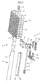
- FIG. 1 is a control line in three-dimensional representation, as well as the supporting device with the electrical lines in an exploded view,
- FIG. 2 is a side elevation of the control line per FIG. 1 , partly cut away,
- FIG. 3 is a front elevation of the control line of FIG. 1 ,
- FIG. 4 is an enlarged representation of the cable storage per FIG. 1 ,
- FIG. 5 is a schematic representation of a suspended control device
- FIG. 6 is a sectional view taken through the control line of FIG. 5 .
- FIG. 7 is a schematic representation of the suspended control device per FIG. 5 .
- FIG. 8 is an illustration of a suspended control device with a common cable with circular cross section
- FIG. 9 is an enlarged representation of the supporting element per FIG. 8 .
- FIG. 10 is an illustration of a suspended control device of telescopically extending tubes
- FIG. 11 is an enlarged representation of the inner tube per FIG. 10 with undercuts for hook elements
- FIG. 12 is an illustration of a suspended control device with a winding frame carrier element
- FIG. 13 is an enlarged representation of the carrier element per FIG. 12 .
- FIG. 14 is an illustration of a suspended control device without tubes, but with a carrier element in the form of a winding frame, and
- FIG. 15 is an enlarged representation of the carrier element per FIG. 14 as a film-hinge cable clamp.
- FIG. 1 shows a control line 1 of a suspended control device 20 (see FIG. 5 ) for the control signals of a unit 21 being controlled (see FIG. 5 ), wherein the suspended control device is fastened at the bottom to the control line 1 , as illustrated in FIG. 1 .
- the suspended control device 20 can be a control switch with a row of pushbuttons, used for example to move a hoisting machine up and down.
- the control line 1 has electrical lines 2 in the form of a cable 3 , at each of whose ends electrical connectors 4 , 5 are secured.
- the electrical lines 2 in the form of a cable 3 serve to transmit control signals from the suspended control device 20 to the unit 21 being controlled, i.e., the hoisting machine in this case.
- the control line 1 comprises a traction relief in the form of a flat foldable hose 6 in the manner of a textile hose.
- the hose 6 like a textile hose, can consist of woven or braided fabric.
- the textile material can be a plastic, as well as natural textile materials.
- the outer diameter of the cable 3 stands to the inner diameter of the hose 6 in a relation of at least 1:3, here, 1:5.
- the hose 6 is supported at the top on the unit 21 via a supporting device 7 , which is formed from a truncated cone 8 and a corresponding (inner) funnel 9 , the truncated cone 8 being located inside the hose 6 .
- the truncated cone 8 can be moved somewhat upward relative to the stationary funnel 9 from the outside, in order to loosen once again the connection between the hose 6 and the unit 21 .
- a hollow cylinder 12 consisting of a solid elastic material and thus forming a firm handle and at the same time a protection for the electrical lines 2 ; the solid elastic material can also extend across the entire lower length of the hose.
- the electrical lines 2 travel through its continuous opening, while a lengthwise slit 13 enables an easier inserting of the electrical lines 2 and cable 3 into the hollow cylinder.
- the hose 6 is filled with an elastic material.
- the elastic material is an elastic foam plastic with appropriate strength.
- the entire traction relief to absorb the gravity and traction forces which occur is provided solely via the hose 6 .
- the hose 6 with the cable 3 running on the inside can also itself travel through a hollow cylinder made from an elastic material, which can thus also enclose the hose 6 on the outside.
- FIG. 2 shows a partially sectioned side view of the control line 1 ;
- FIG. 3 shows the corresponding front view.
- FIG. 2 reveals the cable 3 with the lines 2 running from bottom to top, being laid together flat and folded with the surrounding hose in the upper region and thus forming a cable storage 14 .
- FIG. 2 shows the supporting device 7 in operation, uniformly distributing the gravity and traction forces on the periphery of the hose.
- the truncated cone 8 formed from the two halves is located inside the hose 6 . Its downward displacement is limited by the funnel 9 and its upward displacement by a lug 15 (see FIG. 1 ) on the funnel 9 .
- the element 10 is led in the funnel 15 by means of the guide pins 10 a .
- the funnel 9 is firmly supported against the unit 21 , i.e., the hoisting machine, so that when traction forces occur, the truncated cone 8 is pulled downward, thereby securing the hose axially in relation to the funnel 9 .
- the truncated conical shape must, of course, correspond to the inner funnel of the funnel 9 . In this way, gravity and traction forces are distributed uniformly about the periphery of the hose.
- the truncated cone 8 is provided with a continuous opening 16 , through which travels loosely the cable 3 with the electrical lines 2 . If the element 10 is pushed upward, it carries along the truncated cone 8 through the hose 6 , so that the connection between truncated cone 8 and funnel 9 is again loosened. It is then possible to ease off the tube 6 with the cable 3 from the storage 14 at the top and, with the truncated cone 8 pushed up, to pull it downward through the supporting device 7 , enabling an easy lengthening of the control cable 1 .
- control cable 1 can also be shortened in this way.
- FIG. 4 shows the storage 14 yet again in an enlarged view.
- FIG. 5 shows schematically another suspended control device 20 , which is suspended by a control line 24 from a unit 21 being controlled.
- the control line 24 in the form of a flat cable comprises electrical lines 2 for transmission of control signals and a traction relief 22 at both ends of the cable in the form of steel ropes, which together with the cable are supported on top at the unit 21 .
- the control line 24 is led down from the unit 21 , back up again at a lower turnaround point 22 a , and once more down across a turnaround element 22 b in the form of a roller to the suspended control device 20 .
- the control line 24 is clamped together by means of a detachable clamp 23 in the region of the lower turnaround point 22 a.
- FIG. 6 shows the cross section of the control line 24 .
- FIG. 7 shows a configuration of the suspended control device 20 of FIG. 5 , wherein a deflection roller 26 operating under force of gravity forms the lower turnaround point 22 a and the turnaround element 22 b is likewise fashioned as a deflection roller.
- the flat cable end connected to the suspended control device 20 is at the weight element 25 producing the gravity.
- the flat cable end is led through a continuous opening provided at the weight element 25 .
- the cablelike traction relief 22 and the electrical lines 2 as the control line 24 are again configured as a common cable with circular cross section, being detachably fastened to a platelike support element 28 arranged on the unit 21 .
- the cable storage 14 here is a freely turning cable drum 27 as part of the unit 21 , which is connected by means of a plug connection 36 to the electrical lines 2 .
- the support element 28 has two neighboring continuous openings with a land element in between, around which the cable traveling through the two continuous openings is led for self-clamping fixation.
- FIG. 10 Another suspended control device 20 is shown schematically in FIG. 10 .
- the storage for the electrical lines 2 provided between the suspended control device 20 and the unit 21 is formed in that the electrical lines 2 are led on the inside of an essentially vertical tube 29 fastened to the unit 21 , having a telescopically extending inner tube 30 to which the suspended control device 20 is fastened, and the two flexible tubes 29 , 30 are made of plastic.
- the electrical lines 2 have a spiral shape here.
- the traction relief 22 is a steel rope which can be secured.
- the inner tube 30 can also be provided with undercuts 31 , which engage with pivoting hook elements 32 for axial fixation, being arranged on the outside of the tube 29 .
- the hook elements 32 can also be arranged on the inner tube 30 and the undercuts 31 on the tube 29 .
- FIG. 12 A modification of the suspended control device 20 of FIG. 10 is shown in FIG. 12 , where the electrical lines 2 are wound about a carrier element 33 in the manner of a winding frame inside the two tubes 29 , 30 . Height adjustment is done with a clamping plate 25 a for clamping the steel rope together.
- FIG. 13 An enlarged view of the carrier element 33 in the manner of a winding frame is shown in FIG. 13 .
- the cablelike traction relief 22 and the electrical lines 2 are fashioned as a common flat cable, so that the tubes of FIG. 10 and FIG. 12 can be omitted, and the storage for the cable is formed in that the cable is wound around a carrier element 33 in the manner of a winding frame.
- the carrier element 33 is configured as a cable clamp 34 in the manner of a film joint 34 , as shown in FIG. 15 .
Landscapes
- Engineering & Computer Science (AREA)
- Mechanical Engineering (AREA)
- Automation & Control Theory (AREA)
- Storing, Repeated Paying-Out, And Re-Storing Of Elongated Articles (AREA)
- Load-Engaging Elements For Cranes (AREA)
- Massaging Devices (AREA)
- Selective Calling Equipment (AREA)
- Laying Of Electric Cables Or Lines Outside (AREA)
- Lift-Guide Devices, And Elevator Ropes And Cables (AREA)
- Vehicle Body Suspensions (AREA)
- Installation Of Indoor Wiring (AREA)
Abstract
Description
- 1 Control line
- 2 Electrical lines
- 3 Cable
- 4 Connector
- 5 Connector
- 6 Hose
- 7 Support element
- 8 Truncated cone
- 9 Funnel
- 10 Element
- 10 a Guide pin
- 11 Gripping region
- 12 Hollow cylinder
- 13 Lengthwise slit
- 14 Cable storage
- 15 Lug
- 16 Continuous opening
- 17
- 18
- 19
- 20 Suspended control device
- 21 Unit
- 22 Traction relief
- 22 a Turnaround point
- 22 b Turnaround point
- 23 Clamp
- 24 Control line
- 25 Gravity force
- 26 Deflection roller
- 27 Cable drum
- 28 Support element
- 29 Tube
- 30 Inner tube
- 31 Undercut
- 32 Hook element
- 33 Carrier element
- 34 Cable clamp
- 35 Plug
Claims (28)
Applications Claiming Priority (5)
| Application Number | Priority Date | Filing Date | Title |
|---|---|---|---|
| DE2002131798 DE10231798A1 (en) | 2002-07-10 | 2002-07-10 | Suspension control unit for a hoisting device, has a storage unit for altering length of control cable, by take-up or release of a set length of cable |
| DE10231798.4 | 2002-07-10 | ||
| DE20216079U DE20216079U1 (en) | 2002-07-10 | 2002-10-16 | Suspension control device |
| DE20216079.3 | 2002-10-16 | ||
| PCT/EP2003/006923 WO2004007334A1 (en) | 2002-07-10 | 2003-06-30 | Suspended control device |
Publications (2)
| Publication Number | Publication Date |
|---|---|
| US20060180562A1 US20060180562A1 (en) | 2006-08-17 |
| US7504602B2 true US7504602B2 (en) | 2009-03-17 |
Family
ID=30116636
Family Applications (1)
| Application Number | Title | Priority Date | Filing Date |
|---|---|---|---|
| US10/520,551 Expired - Lifetime US7504602B2 (en) | 2002-07-10 | 2003-06-30 | Suspended control device |
Country Status (11)
| Country | Link |
|---|---|
| US (1) | US7504602B2 (en) |
| EP (1) | EP1494953B1 (en) |
| JP (1) | JP4264063B2 (en) |
| KR (1) | KR100713725B1 (en) |
| CN (1) | CN100337904C (en) |
| AT (1) | ATE328843T1 (en) |
| AU (1) | AU2003258501A1 (en) |
| CA (1) | CA2485381C (en) |
| DE (2) | DE20216079U1 (en) |
| ES (1) | ES2266862T3 (en) |
| WO (1) | WO2004007334A1 (en) |
Cited By (2)
| Publication number | Priority date | Publication date | Assignee | Title |
|---|---|---|---|---|
| USD668424S1 (en) * | 2010-07-20 | 2012-10-02 | Ilcon Gmbh | Patient hoist controller |
| US20140311686A1 (en) * | 2013-04-17 | 2014-10-23 | Teh Yor Co., Ltd. | Motorized Window Shade |
Families Citing this family (5)
| Publication number | Priority date | Publication date | Assignee | Title |
|---|---|---|---|---|
| DE10357659B4 (en) * | 2003-12-10 | 2006-04-13 | Abus Kransysteme Gmbh | Connection of a connector with a control cable |
| DE102006044600A1 (en) * | 2006-09-19 | 2008-03-27 | Stahl Cranesystems Gmbh | Crane with connected wireless control box |
| JP5919008B2 (en) * | 2012-01-31 | 2016-05-18 | 日立オートモティブシステムズ株式会社 | Electric suspension control device |
| JP6223071B2 (en) * | 2013-08-30 | 2017-11-01 | 株式会社タダノ | Boom telescopic mechanism of crane equipment |
| CN104555613A (en) * | 2014-12-25 | 2015-04-29 | 重庆威斯特电梯有限公司 | An elevator for facilitating to fold wires |
Citations (11)
| Publication number | Priority date | Publication date | Assignee | Title |
|---|---|---|---|---|
| DE1819497U (en) | 1959-06-04 | 1960-10-13 | Dickertmann Hebezeugfabrik A G | CRANE CONTROL. |
| US3237780A (en) | 1964-10-14 | 1966-03-01 | Ingersoll Rand Co | Height adjustable pendent control |
| US4042213A (en) * | 1976-06-04 | 1977-08-16 | Columbus Mckinnon Corporation | Electric hoist |
| US4520247A (en) * | 1984-03-05 | 1985-05-28 | Columbus Mckinnon Corporation | Pendant type electrical switching device |
| US4557659A (en) * | 1982-09-14 | 1985-12-10 | M. Scaglia S.P.A. | Device for supporting and handling loads by means of vacuum operated suction pads |
| US4635903A (en) * | 1985-07-29 | 1987-01-13 | Columbus Mckinnon Corporation | Electric hoist pendant control switch arrangement |
| US5507472A (en) * | 1992-09-03 | 1996-04-16 | Mannesmann Aktiengesellschaft | Hoist with a lifting device |
| US5615704A (en) * | 1995-11-02 | 1997-04-01 | Ingersoll-Rand Company | Push Button Pendant for a hoist or winch |
| US6525282B2 (en) * | 2000-03-17 | 2003-02-25 | Atecs Mannesmann Ag | Pendant switch assembly for controlling a movable hoist |
| US6554533B2 (en) * | 2001-04-12 | 2003-04-29 | Byron L. Godbersen | Hydraulic boat hoist |
| US6886812B2 (en) * | 1999-05-13 | 2005-05-03 | Hamayoon Kazerooni | Human power amplifier for lifting load with slack prevention apparatus |
Family Cites Families (8)
| Publication number | Priority date | Publication date | Assignee | Title |
|---|---|---|---|---|
| CH354814A (en) * | 1957-06-18 | 1961-06-15 | Annoni Di Gussola Pier Maria | Multipolar electric cable |
| DE1085310B (en) * | 1957-12-13 | 1960-07-14 | Siemens Ag | One-hand control unit for floor-operated cranes |
| CH580859A5 (en) * | 1974-07-05 | 1976-10-15 | Waldmeier Roger | |
| FR2299675A1 (en) * | 1975-01-31 | 1976-08-27 | Navarro Jose | DIRECTIONAL POSITIONING AND CONTROL SIGNALING STATION |
| DE2535038C3 (en) * | 1975-08-06 | 1978-11-16 | R. Stahl Gmbh & Co, 7000 Stuttgart | Hoist |
| DE2849912C2 (en) * | 1978-11-17 | 1983-05-26 | Mannesmann AG, 4000 Düsseldorf | Strain relief for a control switch hanging on a hoist |
| SU1472418A1 (en) * | 1986-08-22 | 1989-04-15 | Проектно-Конструкторское Бюро Льняной Промышленности | Arrangement for supplying power to moving object |
| DE4234542A1 (en) * | 1992-10-14 | 1994-04-21 | Buehne Werner Abus Kg | Hanging buttons |
-
2002
- 2002-10-16 DE DE20216079U patent/DE20216079U1/en not_active Expired - Lifetime
-
2003
- 2003-06-30 CA CA002485381A patent/CA2485381C/en not_active Expired - Fee Related
- 2003-06-30 JP JP2004520434A patent/JP4264063B2/en not_active Expired - Fee Related
- 2003-06-30 US US10/520,551 patent/US7504602B2/en not_active Expired - Lifetime
- 2003-06-30 AU AU2003258501A patent/AU2003258501A1/en not_active Abandoned
- 2003-06-30 KR KR1020057000358A patent/KR100713725B1/en not_active Expired - Fee Related
- 2003-06-30 ES ES03763667T patent/ES2266862T3/en not_active Expired - Lifetime
- 2003-06-30 AT AT03763667T patent/ATE328843T1/en not_active IP Right Cessation
- 2003-06-30 DE DE50303695T patent/DE50303695D1/en not_active Expired - Lifetime
- 2003-06-30 CN CNB038162768A patent/CN100337904C/en not_active Expired - Lifetime
- 2003-06-30 WO PCT/EP2003/006923 patent/WO2004007334A1/en not_active Ceased
- 2003-06-30 EP EP03763667A patent/EP1494953B1/en not_active Expired - Lifetime
Patent Citations (11)
| Publication number | Priority date | Publication date | Assignee | Title |
|---|---|---|---|---|
| DE1819497U (en) | 1959-06-04 | 1960-10-13 | Dickertmann Hebezeugfabrik A G | CRANE CONTROL. |
| US3237780A (en) | 1964-10-14 | 1966-03-01 | Ingersoll Rand Co | Height adjustable pendent control |
| US4042213A (en) * | 1976-06-04 | 1977-08-16 | Columbus Mckinnon Corporation | Electric hoist |
| US4557659A (en) * | 1982-09-14 | 1985-12-10 | M. Scaglia S.P.A. | Device for supporting and handling loads by means of vacuum operated suction pads |
| US4520247A (en) * | 1984-03-05 | 1985-05-28 | Columbus Mckinnon Corporation | Pendant type electrical switching device |
| US4635903A (en) * | 1985-07-29 | 1987-01-13 | Columbus Mckinnon Corporation | Electric hoist pendant control switch arrangement |
| US5507472A (en) * | 1992-09-03 | 1996-04-16 | Mannesmann Aktiengesellschaft | Hoist with a lifting device |
| US5615704A (en) * | 1995-11-02 | 1997-04-01 | Ingersoll-Rand Company | Push Button Pendant for a hoist or winch |
| US6886812B2 (en) * | 1999-05-13 | 2005-05-03 | Hamayoon Kazerooni | Human power amplifier for lifting load with slack prevention apparatus |
| US6525282B2 (en) * | 2000-03-17 | 2003-02-25 | Atecs Mannesmann Ag | Pendant switch assembly for controlling a movable hoist |
| US6554533B2 (en) * | 2001-04-12 | 2003-04-29 | Byron L. Godbersen | Hydraulic boat hoist |
Cited By (3)
| Publication number | Priority date | Publication date | Assignee | Title |
|---|---|---|---|---|
| USD668424S1 (en) * | 2010-07-20 | 2012-10-02 | Ilcon Gmbh | Patient hoist controller |
| US20140311686A1 (en) * | 2013-04-17 | 2014-10-23 | Teh Yor Co., Ltd. | Motorized Window Shade |
| US9371691B2 (en) * | 2013-04-17 | 2016-06-21 | Teh Yor Co., Ltd. | Motorized window shade |
Also Published As
| Publication number | Publication date |
|---|---|
| EP1494953B1 (en) | 2006-06-07 |
| KR20050017098A (en) | 2005-02-21 |
| JP2005538006A (en) | 2005-12-15 |
| CA2485381A1 (en) | 2004-01-22 |
| HK1075444A1 (en) | 2005-12-16 |
| KR100713725B1 (en) | 2007-05-02 |
| DE20216079U1 (en) | 2003-03-13 |
| DE50303695D1 (en) | 2006-07-20 |
| JP4264063B2 (en) | 2009-05-13 |
| CN1665739A (en) | 2005-09-07 |
| CN100337904C (en) | 2007-09-19 |
| ES2266862T3 (en) | 2007-03-01 |
| WO2004007334A1 (en) | 2004-01-22 |
| EP1494953A1 (en) | 2005-01-12 |
| CA2485381C (en) | 2009-09-29 |
| ATE328843T1 (en) | 2006-06-15 |
| AU2003258501A1 (en) | 2004-02-02 |
| US20060180562A1 (en) | 2006-08-17 |
Similar Documents
| Publication | Publication Date | Title |
|---|---|---|
| US7504602B2 (en) | Suspended control device | |
| GB2050284A (en) | Sheave support for lifting and/or handling machines | |
| JP2021038072A (en) | Work vehicle | |
| JP4488513B2 (en) | Suspended control device | |
| US2110764A (en) | X-ray apparatus | |
| JP3593568B2 (en) | Submarine cable laying method and apparatus | |
| US20030030046A1 (en) | Hoisting mechanism | |
| CN221439935U (en) | Handheld pay-off device | |
| HK1075444B (en) | Suspended control device | |
| JPH10313514A (en) | Cable bridging device | |
| JP3631371B2 (en) | Telescopic boom | |
| JP2001327016A (en) | Stringing construction method for cable and corner guide for cable stringing | |
| KR20260050341A (en) | Pole support device | |
| CN218682544U (en) | Luggage case with external pull rod | |
| US20040033870A1 (en) | Weight compensation device | |
| WO2021020291A1 (en) | Crane | |
| JPH095536A (en) | Fiber optic cable puller | |
| JPH0812255A (en) | Boom structure | |
| JPH09163535A (en) | Auxiliary tool for stringing | |
| KR100283092B1 (en) | Construction of Crane Crane Boom for Hydraulic Crane_ | |
| CN110902469A (en) | Stable transmission auxiliary device for cable | |
| UA66830C2 (en) | Grab equipment of a crane with telescope beam | |
| ITPR970052A1 (en) | CABLE TIE DEVICE FOR ELECTRIC CABLES. | |
| CA2095511A1 (en) | Trolley with luggage securing device |
Legal Events
| Date | Code | Title | Description |
|---|---|---|---|
| AS | Assignment |
Owner name: DEMAG CRANES & COMPONENTS GMBH, GERMANY Free format text: ASSIGNMENT OF ASSIGNORS INTEREST;ASSIGNORS:ROHR, MICHAEL;GERSEMSKY, UDO;KREBS, WOLFGANG;AND OTHERS;REEL/FRAME:017475/0403;SIGNING DATES FROM 20050218 TO 20050317 |
|
| FEPP | Fee payment procedure |
Free format text: PAYOR NUMBER ASSIGNED (ORIGINAL EVENT CODE: ASPN); ENTITY STATUS OF PATENT OWNER: LARGE ENTITY |
|
| STCF | Information on status: patent grant |
Free format text: PATENTED CASE |
|
| FPAY | Fee payment |
Year of fee payment: 4 |
|
| AS | Assignment |
Owner name: TEREX MHPS GMBH, GERMANY Free format text: MERGER AND CHANGE OF NAME;ASSIGNORS:DEMAG CRANES & COMPONENTS GMBH;TEREX MHPS GMBH;REEL/FRAME:034703/0915 Effective date: 20140630 |
|
| AS | Assignment |
Owner name: TEREX MHPS IP MANAGEMENT GMBH, GERMANY Free format text: ASSIGNMENT OF ASSIGNORS INTEREST;ASSIGNOR:TEREX MHPS GMBH;REEL/FRAME:038788/0035 Effective date: 20160429 |
|
| FPAY | Fee payment |
Year of fee payment: 8 |
|
| AS | Assignment |
Owner name: TEREX MHPS GMBH, GERMANY Free format text: MERGER;ASSIGNOR:TEREX MHPS IP MANAGEMENT GMBH;REEL/FRAME:045917/0948 Effective date: 20160829 |
|
| AS | Assignment |
Owner name: DEMAG CRANES & COMPONENTS GMBH, GERMANY Free format text: CHANGE OF NAME;ASSIGNOR:TEREX MHPS GMBH;REEL/FRAME:046162/0643 Effective date: 20171207 |
|
| AS | Assignment |
Owner name: KONECRANES GLOBAL CORPORATION, FINLAND Free format text: ASSIGNMENT OF ASSIGNORS INTEREST;ASSIGNOR:DEMAG CRANES & COMPONENTS GMBH;REEL/FRAME:046460/0274 Effective date: 20180425 |
|
| MAFP | Maintenance fee payment |
Free format text: PAYMENT OF MAINTENANCE FEE, 12TH YEAR, LARGE ENTITY (ORIGINAL EVENT CODE: M1553); ENTITY STATUS OF PATENT OWNER: LARGE ENTITY Year of fee payment: 12 |