US7481960B2 - Mobile straw beam fabricator - Google Patents
Mobile straw beam fabricator Download PDFInfo
- Publication number
- US7481960B2 US7481960B2 US10/908,717 US90871705A US7481960B2 US 7481960 B2 US7481960 B2 US 7481960B2 US 90871705 A US90871705 A US 90871705A US 7481960 B2 US7481960 B2 US 7481960B2
- Authority
- US
- United States
- Prior art keywords
- agricultural product
- product pieces
- straw
- strands
- section
- Prior art date
- Legal status (The legal status is an assumption and is not a legal conclusion. Google has not performed a legal analysis and makes no representation as to the accuracy of the status listed.)
- Expired - Fee Related, expires
Links
- 239000010902 straw Substances 0.000 title claims description 52
- 239000000463 material Substances 0.000 claims abstract description 24
- 239000002699 waste material Substances 0.000 claims abstract description 9
- 230000001070 adhesive effect Effects 0.000 claims description 18
- 239000000853 adhesive Substances 0.000 claims description 16
- 238000000034 method Methods 0.000 claims description 16
- 239000000203 mixture Substances 0.000 claims description 16
- 239000004566 building material Substances 0.000 claims description 10
- 239000000835 fiber Substances 0.000 claims description 5
- 239000004927 clay Substances 0.000 claims description 4
- 239000011398 Portland cement Substances 0.000 claims description 3
- 229920001131 Pulp (paper) Polymers 0.000 claims description 3
- 239000002154 agricultural waste Substances 0.000 abstract description 9
- 239000011230 binding agent Substances 0.000 abstract description 5
- 238000007906 compression Methods 0.000 description 17
- 230000006835 compression Effects 0.000 description 16
- 238000003306 harvesting Methods 0.000 description 7
- 230000003020 moisturizing effect Effects 0.000 description 6
- 238000004519 manufacturing process Methods 0.000 description 5
- 239000002994 raw material Substances 0.000 description 5
- 238000002347 injection Methods 0.000 description 4
- 239000007924 injection Substances 0.000 description 4
- 239000007921 spray Substances 0.000 description 4
- 239000011159 matrix material Substances 0.000 description 3
- 239000011505 plaster Substances 0.000 description 3
- 230000009286 beneficial effect Effects 0.000 description 2
- 238000010276 construction Methods 0.000 description 2
- 230000014509 gene expression Effects 0.000 description 2
- 239000005416 organic matter Substances 0.000 description 2
- 230000001105 regulatory effect Effects 0.000 description 2
- 239000002689 soil Substances 0.000 description 2
- RSWGJHLUYNHPMX-UHFFFAOYSA-N Abietic-Saeure Natural products C12CCC(C(C)C)=CC2=CCC2C1(C)CCCC2(C)C(O)=O RSWGJHLUYNHPMX-UHFFFAOYSA-N 0.000 description 1
- 241000251468 Actinopterygii Species 0.000 description 1
- 235000017166 Bambusa arundinacea Nutrition 0.000 description 1
- 235000017491 Bambusa tulda Nutrition 0.000 description 1
- 244000025254 Cannabis sativa Species 0.000 description 1
- 235000012766 Cannabis sativa ssp. sativa var. sativa Nutrition 0.000 description 1
- 235000012765 Cannabis sativa ssp. sativa var. spontanea Nutrition 0.000 description 1
- 244000073231 Larrea tridentata Species 0.000 description 1
- 235000006173 Larrea tridentata Nutrition 0.000 description 1
- 240000006240 Linum usitatissimum Species 0.000 description 1
- 239000004677 Nylon Substances 0.000 description 1
- 244000082204 Phyllostachys viridis Species 0.000 description 1
- 235000015334 Phyllostachys viridis Nutrition 0.000 description 1
- KHPCPRHQVVSZAH-HUOMCSJISA-N Rosin Natural products O(C/C=C/c1ccccc1)[C@H]1[C@H](O)[C@@H](O)[C@@H](O)[C@@H](CO)O1 KHPCPRHQVVSZAH-HUOMCSJISA-N 0.000 description 1
- 239000004826 Synthetic adhesive Substances 0.000 description 1
- 230000000712 assembly Effects 0.000 description 1
- 238000000429 assembly Methods 0.000 description 1
- 239000011425 bamboo Substances 0.000 description 1
- 239000000227 bioadhesive Substances 0.000 description 1
- 235000009120 camo Nutrition 0.000 description 1
- 229920002678 cellulose Polymers 0.000 description 1
- 239000001913 cellulose Substances 0.000 description 1
- 235000005607 chanvre indien Nutrition 0.000 description 1
- 239000011248 coating agent Substances 0.000 description 1
- 238000000576 coating method Methods 0.000 description 1
- 239000004035 construction material Substances 0.000 description 1
- 238000010924 continuous production Methods 0.000 description 1
- 230000007423 decrease Effects 0.000 description 1
- 238000000151 deposition Methods 0.000 description 1
- 230000003628 erosive effect Effects 0.000 description 1
- 238000009432 framing Methods 0.000 description 1
- 230000005484 gravity Effects 0.000 description 1
- 239000011487 hemp Substances 0.000 description 1
- 238000009413 insulation Methods 0.000 description 1
- 239000000944 linseed oil Substances 0.000 description 1
- 235000021388 linseed oil Nutrition 0.000 description 1
- 230000014759 maintenance of location Effects 0.000 description 1
- 239000002184 metal Substances 0.000 description 1
- 229920001778 nylon Polymers 0.000 description 1
- 229920000728 polyester Polymers 0.000 description 1
- 239000002952 polymeric resin Substances 0.000 description 1
- 238000005086 pumping Methods 0.000 description 1
- 239000003549 soybean oil Substances 0.000 description 1
- 235000012424 soybean oil Nutrition 0.000 description 1
- 239000000126 substance Substances 0.000 description 1
- 229920003002 synthetic resin Polymers 0.000 description 1
- KHPCPRHQVVSZAH-UHFFFAOYSA-N trans-cinnamyl beta-D-glucopyranoside Natural products OC1C(O)C(O)C(CO)OC1OCC=CC1=CC=CC=C1 KHPCPRHQVVSZAH-UHFFFAOYSA-N 0.000 description 1
- 239000002023 wood Substances 0.000 description 1
Images


Classifications
-
- B—PERFORMING OPERATIONS; TRANSPORTING
- B28—WORKING CEMENT, CLAY, OR STONE
- B28B—SHAPING CLAY OR OTHER CERAMIC COMPOSITIONS; SHAPING SLAG; SHAPING MIXTURES CONTAINING CEMENTITIOUS MATERIAL, e.g. PLASTER
- B28B15/00—General arrangement or layout of plant ; Industrial outlines or plant installations
- B28B15/002—Mobile plants, e.g. on vehicles or on boats
-
- B—PERFORMING OPERATIONS; TRANSPORTING
- B28—WORKING CEMENT, CLAY, OR STONE
- B28B—SHAPING CLAY OR OTHER CERAMIC COMPOSITIONS; SHAPING SLAG; SHAPING MIXTURES CONTAINING CEMENTITIOUS MATERIAL, e.g. PLASTER
- B28B1/00—Producing shaped prefabricated articles from the material
- B28B1/52—Producing shaped prefabricated articles from the material specially adapted for producing articles from mixtures containing fibres, e.g. asbestos cement
- B28B1/525—Producing shaped prefabricated articles from the material specially adapted for producing articles from mixtures containing fibres, e.g. asbestos cement containing organic fibres, e.g. wood fibres
Definitions
- building materials made from straw are not capable of supporting the necessary weight without the addition of wood as a framing material, or as a skin applied to a straw panel to give it strength.
- wood as a framing material, or as a skin applied to a straw panel to give it strength.
- maintaining the structural integrity of the straw, by not crushing it also allows for retention of its natural hollow core which has significant insulation value.
- the present invention is a method for creating a building material that makes use of a wheeled, moveable apparatus that moves through a field of agricultural waste product, capturing a portion of the waste product onto the apparatus, aligning the captured waste products parallel to each other into rows, and binding, through the addition of cementatious material, the aligned waste product together to create a cemented product.
- the present invention is an apparatus for producing a cemented product from agricultural waste. It is comprised of a wheeled, moveable frame that includes a capturer adapted to capture a portion of the agricultural waste product onto the frame, an aligner, mounted on the frame, that is adapted to align the longitudinal agricultural waste products into rows, a binder that is adapted to bind the aligned waste products together, and a finisher that adds a cementatious material to the bound waste product, creating a cemented product.
- the present invention is a method for producing a structural product from longitudinal agricultural waste product pieces, each having a natural structure.
- the method consists of arranging the pieces so that they all have the same orientation, compressing the pieces together in a way that preserves their natural structure, binding the pieces together, and placing cementatious material about the bound pieces.
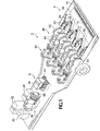
- FIG. 1 is a perspective of a mobile straw beam fabricator according to a preferred embodiment of the present invention.
- FIG. 2 is a side perspective of a mobile straw beam fabricator of FIG. 1 showing a front portion of the fabricator on the bottom part of the drawing, and a rear portion of the fabricator on the top part of the drawing.
- FIG. 3 is a top perspective of the front portion of a mobile straw beam fabricator of FIG. 1 showing four separate compression and first wrapper sections.
- FIG. 4 is a top perspective of the rear portion of a mobile straw beam fabricator of FIG. 1 showing the adhesive injection section, the second wrapper section, and the extruder section.
- FIG. 5 is a cross section of a first wrapper section taken along line 5 - 5 of FIG. 3 .
- FIG. 6 is a cross section of the second wrapper section taken along line 6 - 6 of FIG. 4 .
- FIG. 7 is a cross section of the adhesive injection section taken along line 7 - 7 of FIG. 4 .
- a preferred embodiment of a mobile straw harvester and beam fabricator 2 in the form of a wheeled moveable apparatus, is divided into a front 4 and a rear 6 section.
- the front section 4 harvests straw and fabricates it into four strands 42 ( FIG. 2 ), while the rear section 6 fabricates a beam 44 ( FIG. 2 ) out of the four strands 42 .
- the front section and hence the mobile straw harvester and beam fabricator 2 as a whole, is attached to a tractor by a hitch (not shown) and receives power from the tractor through a power take-off (not shown).
- a tractor pulls the straw harvester 2 by the hitch through a field of straw capturing straw that has been left after the harvesting of grain heads.
- the harvester may be self propelled with its own engine.
- Other raw materials could, however, be used as a substitute.
- bamboo, hemp, chaparral, or other organic substances with fibrous, cellulose-based, stem material could be used. Differing characteristics of the raw material would, of course, result in the production of a finished product whose characteristics, and thus uses, would differ from those obtained when straw is used.
- a cutter bar 12 or capturer, cuts and feeds the straw into the harvester.
- the straw has already been cut and lies in the field in windrows. In such case only a pick-up belt would be needed instead of the cutter bar 12 . Either way, both of these embodiments describe standard equipment for harvesting machines in the industry, which will be familiar to skilled persons.
- a hollow metal tube with multiple spray nozzles 14 sprays the straw with a matrix mixture that is held in, and pumped from, a reservoir 28 ( FIGS. 1 and 4 ).
- the matrix mixture has both moisturizing and adhesive properties. The moisturizing properties are necessary so that the straw can be more easily compressed into a compact cylinder without damaging the structure of the material. The adhesive properties cause the straw to bind together more effectively during subsequent steps of the beam fabrication process.
- the mixture that is sprayed onto the feedstock through the hollow tube with multiple spray nozzles 14 also has a binding element.
- various binders such as clay, boiled linseed or soybean oil, rosin, as well as synthetic and natural adhesives may be part of the mixture that is sprayed onto the feed stock after it is cut and harvested.
- the feed stock After the feed stock is sprayed with the moisturizing and binding elements of the matrix mixture it is carried by a meshed feed belt 16 into one of four parallel compression sections 38 .
- the feed belt is meshed to allow excess moisturizing and binding mixture to fall through to an over-spray tank (not shown) that catches the excess mixture for reuse.
- Three movable vanes 18 separate the feed stock into four streams which enter into one of the four compression sections 38 by passing between a series of converging belts 20 that aligns, or arranges, the straw stems so that they are parallel to each other, and simultaneously compresses them so that they will feed into the compression rollers 40 .
- the compression sections 38 are preceded by four first flow limiting cutters 21 and four sets of parallel belts 23 .
- the first flow limiting cutters 21 and parallel belts 23 limit the swath of feed stock entering the compression sections 38 according to the density of the swath. Greater densities require smaller widths and lesser densities require larger widths.
- the parallel belts 23 compress the straw stems from the top and bottom as well as from the sides.
- the belts 23 are fixed, while on the fourth side (top, bottom, or either side) one of the belts 23 is free to move (in a horizontal or vertical direction) to accommodate for changes in the volume of the material entering the compression process.
- Rollers may be used in the place of belts 23 , depending on the material being processed.
- a second flow limiting cutter 22 removes more excess feed stock material and returns it to the field. Removing excess feed stock assures that only the desired volume of feed stock enters the compression rollers 40 , and that the diameter of the resulting straw strand 42 ( FIGS. 2 and 3 ) is uniform. It also prevents the compression rollers 40 from becoming overloaded. Returning excess feed stock to the field is also beneficial in the sense that it returns organic matter to the soil for the purpose of preserving tilth. Alternatively, the excess material can be further refined and added to the moisturizing and adhesive mixture.
- Feed stock material next passes through the set of compression rollers 40 , each of which has a transversely concave outer surface.
- the distance between the upper rollers 40 and the lower rollers 40 decreases progressively so that the feed stock is gradually compressed to the desired density and diameter.
- the feed stock is held in place by a fixed roller die 54 made from a hard polymer resin ( FIGS. 2 and 3 ).
- the roller die 54 guides the feed stock through the compression section and into the subsequent wrapper section.
- the roller die 54 is a guide block that is machined to be in contact with both the concave face of the rollers and the outer rim of the rollers. As such, the roller die assures that the straw material remains compressed within a columnar space and that no straw slides through the gap between the rollers, which would eventually lead to clogging up the system.
- the compression rollers 40 are able to drive the straw strand 42 through the roller die 54 because the friction created by the die 54 is less than the friction on the compression rollers 40 .
- the resulting cylinder of feed stock is fed into the first wrapper, or binder, section 24 diagramed in FIGS. 2 , 3 , and 5 .
- the first wrapper section entrance nozzle 47 is machined to mate with the exit of the roller die 54 so that the compressed straw column does not have space to expand before it passes into the first wrapper section 24 .
- the first wrapper section 24 consists of a rotating assembly 50 holding two spools 46 of yarn, twine or wire 46 which, fed through an eyelet 48 , is wound around the cylinder as it passes through the center forming a spiral wrapping which binds the material securely together.
- the tension of the yarn, twine or wire 49 ( FIG. 5 ) is regulated by a tensioning roller 56 .
- the rotating assembly 50 is supported in its frame by sets of rollers 52 at each end, and is powered by a drive belt 58 ( FIG. 3 ) attached to the rotating assembly's drive belt pulley 60 .
- each straw strand 42 is bound together with a spiral wrapping of yarn, twine or wire. A twine made out of polyester yarn would work well with the preferred embodiment.
- Each straw strand 42 may next be fed from the front section 4 of the machine into a second stage, in the rear section 6 of the machine, where it will be combined with the three other strands 42 which are being formed simultaneously by the other three first wrapper sections 38 .
- FIG. 3 shows four separate compressing and wrapping units 38 mounted side-by-side in the front section 4 of the mobile straw harvester and beam fabricator.
- the width of the harvested swath necessary to accommodate four parallel wrapping units 38 would equal that made by harvesting equipment currently available.
- the four separate units 38 allow four streams of material to flow to the second, or beam fabrication, stage of the process in the rear section 6 of the machine.
- an optional adhesive injection section 76 (Also seen in FIGS. 1 , 2 and 4 ) that the four straw strands 42 pass through before reaching the second wrapper section 26 .
- the optional adhesive injection section 76 may be used to inject an adhesive mixture into what will become the core of the beam 44 . This is done by pumping an adhesive mixture between the middle two strands 42 when the four strands 42 are still parallel and grouped together horizontally on the aligning rollers 41 .
- the outer two strands 42 are raised up by beam forming rollers (not shown for ease of presentation) and brought together on top of the idle inner strands 42 so that the adhesive mixture is in between the four strands 42 .
- the adhesive mixture may be a papercrete mixture consisting of paper pulp, clay, Portland cement, straw fiber and other adhesive materials.
- the four straw strands 42 are fed into the second, and subsequent, wrapper, or binder, section 26 which is shown in FIGS. 1 , 2 , 4 and 6 .
- the second wrapper section 26 works on the same principles as the first wrapper sections 24 except that, having a larger diameter, the second wrapper section is capable of accommodating the greater volume created by combining the four straw strands 42 from the four first wrapper section units.
- the four straw strands 42 pass through the rotating assembly 66 , and are bound together into a single beam 44 ( FIG. 2 ) by yarn, twine or wire held on one or more spools 62 held by the rotating assembly 66 and fed through an eyelet 64 .
- the rotating assembly 66 is supported in its frame by sets of rollers 52 at each end.
- the second wrapper section may be powered, as the first sections are, by a drive belt 72 ( FIG. 4 ) attached to a drive belt pulley 74 that is connected to the rotating assembly 66 or, alternatively, it may be powered by a drive chain attached to a drive chain sprocket connected to the rotating assembly 66 .
- the beam 44 then passes into an extruder, or finishing, section 30 where four concave traction rollers (not shown), oriented at 90 degree angles, square the beam and simultaneously eliminate unwanted moisture through compression.
- the squared beam 44 is then coated on one or more sides with a uniform, approximately 0.5′′ layer of exterior plaster, or fiber adobe, composed of the same adhesive mixture of paper pulp, clay, Portland cement, and other adhesive materials that was previously injected into the core.
- the exterior plaster is pumped from tank 32 and placed upon the beam by a nylon trowel (not shown).
- the beam 44 After passing through the extruder, or finisher, 30 the beam 44 enters a vibrating trowel 34 which further compresses and smoothes the fiber adobe exterior plaster. This assures that a good bond is formed between the beam and the fiber adobe coating.
- the completed beam is then deposited from the rear of the machine into the field to dry. When the beam dries, it can be cut to length and transported. Alternatively, a saw could be placed at the rear of the machine, before or after the vibrating trowel 34 , to cut the beam into predetermined lengths before depositing the cut beams into the field.
- the finished beam, properly dried can either be maintained in its continuous state for such purposes as erosion control, or restoration of fish habitat in streams, etc., or can be cut for use as construction beams and used for such purposes as the construction of load bearing walls.
- the machine would be stationary and located at a central location to which the raw material could be transported.
- the raw material would then be fed into the beam fabricator either by hand, or through some sort of automatic feed.
- This alternative would be particularly relevant where mechanical harvest is not available, or the particular raw material being used does not lend itself to mechanical harvest.
- the feed mechanism could be made larger to accommodate brush and other more rigid materials. Additional rotating saw blades would trim off branches that could not be compressed. The compression and wrapper assemblies would also have to be larger to accommodate the strands and beams that would be fabricated.
Landscapes
- Engineering & Computer Science (AREA)
- Chemical & Material Sciences (AREA)
- Ceramic Engineering (AREA)
- Mechanical Engineering (AREA)
- Life Sciences & Earth Sciences (AREA)
- Wood Science & Technology (AREA)
- Manufacturing & Machinery (AREA)
- Paper (AREA)
- Yarns And Mechanical Finishing Of Yarns Or Ropes (AREA)
- Dry Formation Of Fiberboard And The Like (AREA)
Abstract
An apparatus for producing a cemented product from agricultural waste. The apparatus is comprised of a wheeled, moveable frame that holds a capturer adapted to capture a portion of the agricultural waste product onto the frame, an aligner, mounted on the frame, that is adapted to align the longitudinal agricultural waste products into rows, a binder that is adapted to bind the aligned waste products together, and a finisher that adds a cementatious material to the bound waste product, creating a cemented product.
Description
This application claims priority from provisional application Ser. No. 60/592,558 filed Aug. 2, 2004.
Finding a beneficial use for the large quantities of agricultural waste material produced in the world has been a pursuit of interest to agriculturalists for a very long time. Although many clever innovations have been made, there is still a problem of disposing of this waste in a useful manner. Additionally, there is a constant search for inexpensive building materials. Again, although much progress has been made in this area, there is still a need for additional options in construction materials.
The structural qualities of straw, in its natural undamaged form, provide significant compressive strength. Compressive strength is precisely the type of strength needed in building materials that are used to support heavy loads. In the prior art the structural integrity of the stalks is lost in two ways. First, in the way the straw is bailed for transportation to the building material fabrication facility and, second, in the way the straw is processed into building material. First, in the prior art the method of bailing straw crushes and breaks the straw stalks so that its natural integrity is injured before even beginning the processing phase. Second, when the straw is processed into building materials it is compressed into a dense mass under heat and pressure. In the process the straw is further crushed, hence further losing its natural structural integrity which, in turn, results in the loss of the straw's natural compressive strength. Accordingly, building materials made from straw, under the prior art, are not capable of supporting the necessary weight without the addition of wood as a framing material, or as a skin applied to a straw panel to give it strength. In addition to preserving compressive strength, maintaining the structural integrity of the straw, by not crushing it, also allows for retention of its natural hollow core which has significant insulation value.
In a first separate aspect, the present invention is a method for creating a building material that makes use of a wheeled, moveable apparatus that moves through a field of agricultural waste product, capturing a portion of the waste product onto the apparatus, aligning the captured waste products parallel to each other into rows, and binding, through the addition of cementatious material, the aligned waste product together to create a cemented product.
In a second separate aspect, the present invention is an apparatus for producing a cemented product from agricultural waste. It is comprised of a wheeled, moveable frame that includes a capturer adapted to capture a portion of the agricultural waste product onto the frame, an aligner, mounted on the frame, that is adapted to align the longitudinal agricultural waste products into rows, a binder that is adapted to bind the aligned waste products together, and a finisher that adds a cementatious material to the bound waste product, creating a cemented product.
In a third separate aspect, the present invention is a method for producing a structural product from longitudinal agricultural waste product pieces, each having a natural structure. The method consists of arranging the pieces so that they all have the same orientation, compressing the pieces together in a way that preserves their natural structure, binding the pieces together, and placing cementatious material about the bound pieces.
The foregoing and other objectives, features and advantages of the invention will be more readily understood upon consideration of the following detailed description of the preferred embodiment(s), taken in conjunction with the accompanying drawings.
Referring to FIGS. 1 , 2 and 3, a preferred embodiment of a mobile straw harvester and beam fabricator 2, in the form of a wheeled moveable apparatus, is divided into a front 4 and a rear 6 section. The front section 4 harvests straw and fabricates it into four strands 42 (FIG. 2 ), while the rear section 6 fabricates a beam 44 (FIG. 2 ) out of the four strands 42. The front section and hence the mobile straw harvester and beam fabricator 2 as a whole, is attached to a tractor by a hitch (not shown) and receives power from the tractor through a power take-off (not shown). In the preferred embodiment a tractor pulls the straw harvester 2 by the hitch through a field of straw capturing straw that has been left after the harvesting of grain heads. In an alternative embodiment, the harvester may be self propelled with its own engine. Other raw materials could, however, be used as a substitute. For example, bamboo, hemp, chaparral, or other organic substances with fibrous, cellulose-based, stem material could be used. Differing characteristics of the raw material would, of course, result in the production of a finished product whose characteristics, and thus uses, would differ from those obtained when straw is used.
As the tractor pulls the mobile straw harvester and beam fabricator 2 through a field of straw left after the harvesting of grain heads a cutter bar 12, or capturer, cuts and feeds the straw into the harvester. In an alternative embodiment the straw has already been cut and lies in the field in windrows. In such case only a pick-up belt would be needed instead of the cutter bar 12. Either way, both of these embodiments describe standard equipment for harvesting machines in the industry, which will be familiar to skilled persons.
When the feed stock (typically straw) is gathered into the harvester a hollow metal tube with multiple spray nozzles 14 sprays the straw with a matrix mixture that is held in, and pumped from, a reservoir 28 (FIGS. 1 and 4 ). The matrix mixture has both moisturizing and adhesive properties. The moisturizing properties are necessary so that the straw can be more easily compressed into a compact cylinder without damaging the structure of the material. The adhesive properties cause the straw to bind together more effectively during subsequent steps of the beam fabrication process.
Regulating the moisture so that the feed stock can be more easily compressed into a compact cylinder without damaging the structure of the material is an important element of the present embodiment. As noted in the background section, the structural qualities of straw, in its natural undamaged form, provide significant compressive strength. Compressive strength is precisely the type of strength needed in building materials that are used to support heavy loads. This is one great advantage this process has over the prior art.
In addition to the moisturizing value, the mixture that is sprayed onto the feedstock through the hollow tube with multiple spray nozzles 14 also has a binding element. Hence various binders such as clay, boiled linseed or soybean oil, rosin, as well as synthetic and natural adhesives may be part of the mixture that is sprayed onto the feed stock after it is cut and harvested.
After the feed stock is sprayed with the moisturizing and binding elements of the matrix mixture it is carried by a meshed feed belt 16 into one of four parallel compression sections 38. The feed belt is meshed to allow excess moisturizing and binding mixture to fall through to an over-spray tank (not shown) that catches the excess mixture for reuse.
Three movable vanes 18 separate the feed stock into four streams which enter into one of the four compression sections 38 by passing between a series of converging belts 20 that aligns, or arranges, the straw stems so that they are parallel to each other, and simultaneously compresses them so that they will feed into the compression rollers 40.
The compression sections 38 are preceded by four first flow limiting cutters 21 and four sets of parallel belts 23. The first flow limiting cutters 21 and parallel belts 23 limit the swath of feed stock entering the compression sections 38 according to the density of the swath. Greater densities require smaller widths and lesser densities require larger widths.
In an alternative embodiment the parallel belts 23 compress the straw stems from the top and bottom as well as from the sides. On three sides of the feed stock the belts 23 are fixed, while on the fourth side (top, bottom, or either side) one of the belts 23 is free to move (in a horizontal or vertical direction) to accommodate for changes in the volume of the material entering the compression process. Rollers may be used in the place of belts 23, depending on the material being processed.
After passing through the set of parallel belts 23, but before entering the compression rollers 40, a second flow limiting cutter 22 (FIGS. 2 and 3 ) removes more excess feed stock material and returns it to the field. Removing excess feed stock assures that only the desired volume of feed stock enters the compression rollers 40, and that the diameter of the resulting straw strand 42 (FIGS. 2 and 3 ) is uniform. It also prevents the compression rollers 40 from becoming overloaded. Returning excess feed stock to the field is also beneficial in the sense that it returns organic matter to the soil for the purpose of preserving tilth. Alternatively, the excess material can be further refined and added to the moisturizing and adhesive mixture.
Feed stock material next passes through the set of compression rollers 40, each of which has a transversely concave outer surface. The distance between the upper rollers 40 and the lower rollers 40 decreases progressively so that the feed stock is gradually compressed to the desired density and diameter.
During compression, the feed stock is held in place by a fixed roller die 54 made from a hard polymer resin (FIGS. 2 and 3 ). The roller die 54 guides the feed stock through the compression section and into the subsequent wrapper section. The roller die 54 is a guide block that is machined to be in contact with both the concave face of the rollers and the outer rim of the rollers. As such, the roller die assures that the straw material remains compressed within a columnar space and that no straw slides through the gap between the rollers, which would eventually lead to clogging up the system. The compression rollers 40 are able to drive the straw strand 42 through the roller die 54 because the friction created by the die 54 is less than the friction on the compression rollers 40.
The resulting cylinder of feed stock is fed into the first wrapper, or binder, section 24 diagramed in FIGS. 2 , 3, and 5. The first wrapper section entrance nozzle 47 is machined to mate with the exit of the roller die 54 so that the compressed straw column does not have space to expand before it passes into the first wrapper section 24. The first wrapper section 24 consists of a rotating assembly 50 holding two spools 46 of yarn, twine or wire 46 which, fed through an eyelet 48, is wound around the cylinder as it passes through the center forming a spiral wrapping which binds the material securely together. The tension of the yarn, twine or wire 49 (FIG. 5 ) is regulated by a tensioning roller 56. The rotating assembly 50 is supported in its frame by sets of rollers 52 at each end, and is powered by a drive belt 58 (FIG. 3 ) attached to the rotating assembly's drive belt pulley 60.
The result of the foregoing continuous process are four straw strands 42, one from each of the four first wrapper sections 24, each of equal diameter, which depending on the embodiment and setting may range from 1″ to 9″. Each strand 42 is bound together with a spiral wrapping of yarn, twine or wire. A twine made out of polyester yarn would work well with the preferred embodiment. Each straw strand 42 may next be fed from the front section 4 of the machine into a second stage, in the rear section 6 of the machine, where it will be combined with the three other strands 42 which are being formed simultaneously by the other three first wrapper sections 38.
In FIG. 7 we can see an optional adhesive injection section 76 (Also seen in FIGS. 1 , 2 and 4) that the four straw strands 42 pass through before reaching the second wrapper section 26. The optional adhesive injection section 76 may be used to inject an adhesive mixture into what will become the core of the beam 44. This is done by pumping an adhesive mixture between the middle two strands 42 when the four strands 42 are still parallel and grouped together horizontally on the aligning rollers 41. After exiting the optional adhesive section 76, but before entering the second wrapper section 26, the outer two strands 42 are raised up by beam forming rollers (not shown for ease of presentation) and brought together on top of the idle inner strands 42 so that the adhesive mixture is in between the four strands 42.
When the four strands 42 are wrapped together in the second wrapper section 26 the adhesive will serve to bind the four straw strands 42 together more securely. In the mobile unit the adhesive mixture is pumped from a rear tank 32. In an alternative, stationary, unit a gravity fed system is used, saving the expense of a pump. The adhesive mixture may be a papercrete mixture consisting of paper pulp, clay, Portland cement, straw fiber and other adhesive materials.
In the rear section 6 of the mobile straw harvester and beam fabricator 2 the four straw strands 42 are fed into the second, and subsequent, wrapper, or binder, section 26 which is shown in FIGS. 1 , 2, 4 and 6. The second wrapper section 26 works on the same principles as the first wrapper sections 24 except that, having a larger diameter, the second wrapper section is capable of accommodating the greater volume created by combining the four straw strands 42 from the four first wrapper section units. The four straw strands 42, pass through the rotating assembly 66, and are bound together into a single beam 44 (FIG. 2 ) by yarn, twine or wire held on one or more spools 62 held by the rotating assembly 66 and fed through an eyelet 64. The rotating assembly 66 is supported in its frame by sets of rollers 52 at each end. The second wrapper section may be powered, as the first sections are, by a drive belt 72 (FIG. 4 ) attached to a drive belt pulley 74 that is connected to the rotating assembly 66 or, alternatively, it may be powered by a drive chain attached to a drive chain sprocket connected to the rotating assembly 66.
Referring to FIGS. 2 and 4 , the beam 44 then passes into an extruder, or finishing, section 30 where four concave traction rollers (not shown), oriented at 90 degree angles, square the beam and simultaneously eliminate unwanted moisture through compression. The squared beam 44 is then coated on one or more sides with a uniform, approximately 0.5″ layer of exterior plaster, or fiber adobe, composed of the same adhesive mixture of paper pulp, clay, Portland cement, and other adhesive materials that was previously injected into the core. The exterior plaster is pumped from tank 32 and placed upon the beam by a nylon trowel (not shown).
After passing through the extruder, or finisher, 30 the beam 44 enters a vibrating trowel 34 which further compresses and smoothes the fiber adobe exterior plaster. This assures that a good bond is formed between the beam and the fiber adobe coating. The completed beam is then deposited from the rear of the machine into the field to dry. When the beam dries, it can be cut to length and transported. Alternatively, a saw could be placed at the rear of the machine, before or after the vibrating trowel 34, to cut the beam into predetermined lengths before depositing the cut beams into the field.
The entire process allows a predetermined percentage of straw to be left in the field to preserve the required content of organic matter in the soil. Neither burning nor bailing is able to accomplish this.
The finished beam, properly dried, can either be maintained in its continuous state for such purposes as erosion control, or restoration of fish habitat in streams, etc., or can be cut for use as construction beams and used for such purposes as the construction of load bearing walls.
In an alternative embodiment the machine would be stationary and located at a central location to which the raw material could be transported. The raw material would then be fed into the beam fabricator either by hand, or through some sort of automatic feed. This alternative would be particularly relevant where mechanical harvest is not available, or the particular raw material being used does not lend itself to mechanical harvest.
In another alternative embodiment the feed mechanism could be made larger to accommodate brush and other more rigid materials. Additional rotating saw blades would trim off branches that could not be compressed. The compression and wrapper assemblies would also have to be larger to accommodate the strands and beams that would be fabricated.
The terms and expressions that have been employed in the foregoing specification are used as terms of description and not of limitation. There is no intention, in the use of such terms and expressions, of excluding equivalents of the features shown and described or portions thereof, it being recognized that the scope of the invention is defined and limited only by the claims which follow.
Claims (7)
1. A method for creating a building material:
(a) providing a wheeled, moveable apparatus;
(b) moving said apparatus through a field having agricultural product pieces;
(c) capturing a portion of said agricultural product pieces onto said apparatus, as it is moved through said field;
(d) aligning said captured agricultural product pieces, on said apparatus, to create aligned product pieces;
(e) binding a plurality of said aligned agricultural product pieces together by a spiral wrapping, on said apparatus to create a strand of spiral wrapped agricultural product pieces, and binding together an additional plurality of aligned agricultural product pieces to form a plurality of strands of agricultural product pieces;
(f) wrapping said plurality of strands together, on said apparatus, to form a wrapped plurality of agricultural product pieces strands; and
(g) adding cementatious material to said wrapped plurality of agricultural product pieces strands, on said apparatus, to form a cemented piece of building material, suitable for bearing loads.
2. The method of claim 1 , wherein said agricultural product is straw.
3. The method of claim 1 , wherein said agricultural product pieces are compressed before they are bound, so that the result is plurality of agricultural product pieces that are bound together in a state of being compressed together.
4. The method of claim 1 , wherein a cementatious material is placed in the center of said bound group of strands.
5. The method of claim 1 , wherein the cementatious material is composed of a papercrete mixture consisting of paper pulp, clay, Portland cement, straw fiber and other adhesive materials.
6. The method of claim 1 , wherein said agricultural product pieces are waste product pieces.
7. The method of claim 1 , wherein said agricultural product pieces have a natural structure and wherein this natural structure is preserved during said method.
Priority Applications (1)
| Application Number | Priority Date | Filing Date | Title |
|---|---|---|---|
| US10/908,717 US7481960B2 (en) | 2004-08-02 | 2005-05-24 | Mobile straw beam fabricator |
Applications Claiming Priority (2)
| Application Number | Priority Date | Filing Date | Title |
|---|---|---|---|
| US59255804P | 2004-08-02 | 2004-08-02 | |
| US10/908,717 US7481960B2 (en) | 2004-08-02 | 2005-05-24 | Mobile straw beam fabricator |
Publications (2)
| Publication Number | Publication Date |
|---|---|
| US20060022373A1 US20060022373A1 (en) | 2006-02-02 |
| US7481960B2 true US7481960B2 (en) | 2009-01-27 |
Family
ID=35839832
Family Applications (1)
| Application Number | Title | Priority Date | Filing Date |
|---|---|---|---|
| US10/908,717 Expired - Fee Related US7481960B2 (en) | 2004-08-02 | 2005-05-24 | Mobile straw beam fabricator |
Country Status (2)
| Country | Link |
|---|---|
| US (1) | US7481960B2 (en) |
| WO (1) | WO2006017434A2 (en) |
Cited By (2)
| Publication number | Priority date | Publication date | Assignee | Title |
|---|---|---|---|---|
| US8905097B2 (en) | 2012-02-01 | 2014-12-09 | Bridgestone Americas Tire Operations, Llc | Agricultural tire tread |
| US11661740B2 (en) | 2021-10-07 | 2023-05-30 | ORB Technologies, LLC | System, apparatus, and method for providing a plant-based structural assembly |
Families Citing this family (3)
| Publication number | Priority date | Publication date | Assignee | Title |
|---|---|---|---|---|
| US8309221B2 (en) * | 2007-10-01 | 2012-11-13 | Jay Plaehn | Reinforced foam panel |
| HU230624B1 (en) | 2013-10-29 | 2017-04-28 | Molnárbeton Betongyártó És Kereskedelmi Kft | Method for producing cellulose - based concrete products with reduced hydration and the use of said concrete product |
| CN109291221B (en) * | 2016-12-30 | 2020-09-08 | 绍兴柯桥新兴门业有限公司 | Can press from both sides tight ceramic glaze spraying machine of product |
Citations (12)
| Publication number | Priority date | Publication date | Assignee | Title |
|---|---|---|---|---|
| US2627714A (en) * | 1951-02-13 | 1953-02-10 | Jr Percy F Freeman | Hay baler |
| US4327537A (en) * | 1978-09-05 | 1982-05-04 | Milo Wolrab | Method of sealing forage packages |
| US4399745A (en) | 1980-02-06 | 1983-08-23 | Sikob Svensk Industris Konstruktions-Och Berakningskontor Ab | Method of bundling brushwood |
| US4451322A (en) | 1982-04-23 | 1984-05-29 | Richard A. Moerman | Apparatus for forming structural sheets from fibrous biological waste |
| US5498469A (en) | 1994-12-02 | 1996-03-12 | Howard; Robert E. | Thin panels of non-woody lignocellulosic material |
| US5730830A (en) | 1995-12-26 | 1998-03-24 | Haddonfield Management Co. Ltd. | Fiber panel manufacturing method and apparatus |
| US5729936A (en) | 1995-10-03 | 1998-03-24 | Maxwell; James F. | Prefab fiber building construction |
| US5932038A (en) | 1997-07-24 | 1999-08-03 | Alberta Research Council | Method of fabricating a straw panel, board, or beam |
| US5945132A (en) | 1997-01-30 | 1999-08-31 | Agriboard Industries | Apparatus for making compressed agricultural fiber structural board |
| CA2312657A1 (en) * | 1999-06-30 | 2000-12-30 | Shinichi Kaneko | Building boards, manufacturing apparatus and prefoamed plastics |
| US6209284B1 (en) | 1999-03-01 | 2001-04-03 | William H. Porter | Asymmetric structural insulated panels for use in 2X stick construction |
| US6596209B2 (en) | 2000-08-10 | 2003-07-22 | California Agriboard Llc | Production of particle board from agricultural waste |
-
2005
- 2005-05-24 US US10/908,717 patent/US7481960B2/en not_active Expired - Fee Related
- 2005-08-01 WO PCT/US2005/027247 patent/WO2006017434A2/en active Application Filing
Patent Citations (12)
| Publication number | Priority date | Publication date | Assignee | Title |
|---|---|---|---|---|
| US2627714A (en) * | 1951-02-13 | 1953-02-10 | Jr Percy F Freeman | Hay baler |
| US4327537A (en) * | 1978-09-05 | 1982-05-04 | Milo Wolrab | Method of sealing forage packages |
| US4399745A (en) | 1980-02-06 | 1983-08-23 | Sikob Svensk Industris Konstruktions-Och Berakningskontor Ab | Method of bundling brushwood |
| US4451322A (en) | 1982-04-23 | 1984-05-29 | Richard A. Moerman | Apparatus for forming structural sheets from fibrous biological waste |
| US5498469A (en) | 1994-12-02 | 1996-03-12 | Howard; Robert E. | Thin panels of non-woody lignocellulosic material |
| US5729936A (en) | 1995-10-03 | 1998-03-24 | Maxwell; James F. | Prefab fiber building construction |
| US5730830A (en) | 1995-12-26 | 1998-03-24 | Haddonfield Management Co. Ltd. | Fiber panel manufacturing method and apparatus |
| US5945132A (en) | 1997-01-30 | 1999-08-31 | Agriboard Industries | Apparatus for making compressed agricultural fiber structural board |
| US5932038A (en) | 1997-07-24 | 1999-08-03 | Alberta Research Council | Method of fabricating a straw panel, board, or beam |
| US6209284B1 (en) | 1999-03-01 | 2001-04-03 | William H. Porter | Asymmetric structural insulated panels for use in 2X stick construction |
| CA2312657A1 (en) * | 1999-06-30 | 2000-12-30 | Shinichi Kaneko | Building boards, manufacturing apparatus and prefoamed plastics |
| US6596209B2 (en) | 2000-08-10 | 2003-07-22 | California Agriboard Llc | Production of particle board from agricultural waste |
Cited By (4)
| Publication number | Priority date | Publication date | Assignee | Title |
|---|---|---|---|---|
| US8905097B2 (en) | 2012-02-01 | 2014-12-09 | Bridgestone Americas Tire Operations, Llc | Agricultural tire tread |
| USD731401S1 (en) | 2012-02-01 | 2015-06-09 | Bridgestone Americas Tire Operations, Llc | Tire tread |
| US9764597B2 (en) | 2012-02-01 | 2017-09-19 | Bridgestone Americas Tires Operations, LLC | Agricultural tire tread |
| US11661740B2 (en) | 2021-10-07 | 2023-05-30 | ORB Technologies, LLC | System, apparatus, and method for providing a plant-based structural assembly |
Also Published As
| Publication number | Publication date |
|---|---|
| WO2006017434A2 (en) | 2006-02-16 |
| WO2006017434A3 (en) | 2008-05-08 |
| US20060022373A1 (en) | 2006-02-02 |
Similar Documents
| Publication | Publication Date | Title |
|---|---|---|
| US7481960B2 (en) | Mobile straw beam fabricator | |
| US7537031B2 (en) | System and method for the manufacture of reconsolidated or reconstituted wood products | |
| EP2556742B1 (en) | Agricultural baler | |
| DE2716748A1 (en) | RECONSOLIDATED WOOD MATERIAL AND PROCESS AND DEVICE FOR ITS PRODUCTION | |
| US9107342B2 (en) | Method for harvesting bast plants | |
| AT396948B (en) | METHOD AND DEVICE FOR REMOVING AND PREPARING FLAT | |
| DE2360866A1 (en) | LONG STRETCHED BOARD, BEAM OR THE LIKE. AND METHOD AND DEVICE FOR ITS MANUFACTURING | |
| EP1181138B1 (en) | Hemp hurd composite panels | |
| US20090120597A1 (en) | Method and apparatus for removing sheets of fibres from banana plants for the production of paper products | |
| DD209772A5 (en) | APPENDIX FOR THE PRODUCTION OF BUILDING PLATES FROM BIOLOGICAL FIBER WASTE | |
| CN105637127B (en) | For the separated apparatus and method from axis bast by bast and wood body | |
| DE3735235C2 (en) | Green flax harvester | |
| JPS61500484A (en) | Improved method for manufacturing reconsolidated wood products | |
| DE102011109891B4 (en) | Round agricultural baler | |
| DE2626263A1 (en) | Large dia. bale roller - has hydraulic cylinders to raise and lower top and front endless sections of forming belt | |
| DE19712440A1 (en) | Chipboard/fibreboard manufacturing appliance | |
| DE102011111401B4 (en) | Round agricultural baler | |
| EP1932643A2 (en) | Method for manufacturing a glueable substance from fibrous plants and substance plates made thereof | |
| EP2683534A1 (en) | Method and system for producing a material panel, in particular a high-density material panel, and material panel | |
| DE2318284A1 (en) | DEVICE FOR FEEDING CONTINUOUSLY WORKING COMPOSITE PRESSES | |
| US7699951B2 (en) | Fabrication of composite panels from cable made from oriented agricultural byproducts | |
| WO2011029904A1 (en) | System for converting wood fibres into a state processed by metering devices, prepared wood fibre material and extrudate produced therefrom | |
| CN102333920A (en) | Improved fibre furnish | |
| EP2167618B1 (en) | Method and apparatus for producing shaped fuel elements from biomass material, and the corresponding shaped fuel element | |
| WO2005087467A1 (en) | Three-dimensional structure consisting of natural fibers in the form of matting, panels, hollow bodies, molded parts or the like. |
Legal Events
| Date | Code | Title | Description |
|---|---|---|---|
| AS | Assignment |
Owner name: ASHLAND SCHOOL OF ENVIRONMENTAL TECHNOLOGY, OREGON Free format text: ASSIGNMENT OF ASSIGNORS INTEREST;ASSIGNOR:WARD, DAVID;REEL/FRAME:016834/0351 Effective date: 20050729 |
|
| REMI | Maintenance fee reminder mailed | ||
| FPAY | Fee payment |
Year of fee payment: 4 |
|
| SULP | Surcharge for late payment | ||
| REMI | Maintenance fee reminder mailed | ||
| LAPS | Lapse for failure to pay maintenance fees | ||
| STCH | Information on status: patent discontinuation |
Free format text: PATENT EXPIRED DUE TO NONPAYMENT OF MAINTENANCE FEES UNDER 37 CFR 1.362 |
|
| FP | Lapsed due to failure to pay maintenance fee |
Effective date: 20170127 |