US7479724B2 - Stator structure - Google Patents
Stator structure Download PDFInfo
- Publication number
- US7479724B2 US7479724B2 US11/714,258 US71425807A US7479724B2 US 7479724 B2 US7479724 B2 US 7479724B2 US 71425807 A US71425807 A US 71425807A US 7479724 B2 US7479724 B2 US 7479724B2
- Authority
- US
- United States
- Prior art keywords
- stator
- notches
- stator part
- parts
- projections
- Prior art date
- Legal status (The legal status is an assumption and is not a legal conclusion. Google has not performed a legal analysis and makes no representation as to the accuracy of the status listed.)
- Expired - Fee Related
Links
- 239000000463 material Substances 0.000 claims abstract description 9
- 229910000976 Electrical steel Inorganic materials 0.000 claims description 20
- 229910000831 Steel Inorganic materials 0.000 abstract 1
- 239000010959 steel Substances 0.000 abstract 1
- 238000004519 manufacturing process Methods 0.000 description 6
- 238000005096 rolling process Methods 0.000 description 4
- 238000012986 modification Methods 0.000 description 3
- 230000004048 modification Effects 0.000 description 3
- XEEYBQQBJWHFJM-UHFFFAOYSA-N Iron Chemical compound [Fe] XEEYBQQBJWHFJM-UHFFFAOYSA-N 0.000 description 2
- 238000001816 cooling Methods 0.000 description 2
- 238000001746 injection moulding Methods 0.000 description 2
- 238000003825 pressing Methods 0.000 description 2
- XUIMIQQOPSSXEZ-UHFFFAOYSA-N Silicon Chemical compound [Si] XUIMIQQOPSSXEZ-UHFFFAOYSA-N 0.000 description 1
- 230000035508 accumulation Effects 0.000 description 1
- 238000009825 accumulation Methods 0.000 description 1
- 239000002131 composite material Substances 0.000 description 1
- 238000005520 cutting process Methods 0.000 description 1
- 238000009413 insulation Methods 0.000 description 1
- 239000012212 insulator Substances 0.000 description 1
- 229910052742 iron Inorganic materials 0.000 description 1
- 238000003754 machining Methods 0.000 description 1
- 238000000034 method Methods 0.000 description 1
- 238000004080 punching Methods 0.000 description 1
- 229910052710 silicon Inorganic materials 0.000 description 1
- 239000010703 silicon Substances 0.000 description 1
Images


Classifications
-
- H—ELECTRICITY
- H02—GENERATION; CONVERSION OR DISTRIBUTION OF ELECTRIC POWER
- H02K—DYNAMO-ELECTRIC MACHINES
- H02K1/00—Details of the magnetic circuit
- H02K1/06—Details of the magnetic circuit characterised by the shape, form or construction
- H02K1/12—Stationary parts of the magnetic circuit
- H02K1/14—Stator cores with salient poles
- H02K1/145—Stator cores with salient poles having an annular coil, e.g. of the claw-pole type
Definitions
- the present invention relates to a composite stator structure and in particular to a stator structure in a cooling fan.
- FIG. 1 shows a conventional brushless DC motor.
- the motor comprises a magnetic sleeve 10 , a first bobbin 11 , a second bobbin 12 , a first pole plate 13 , a second pole plate 14 , and a third pole plate 15 .
- the second pole plate 14 , second bobbin 12 , third pole plate 15 , first bobbin 11 , and first pole plate 13 are sequentially tightly assembled with the magnetic sleeve 10 .
- Protrusions 111 and 121 on the first and second bobbins 11 and 12 must be engaged with the holes 131 , 141 , and 151 on the first, second, and third pole plates 13 , 14 , and 15 respectively so as to complete the position and angle of the first, second and third pole plates 13 , 14 , and 15 .
- the first and second bobbins 11 and 12 are made of plastic, and the first, second and third pole plates 13 , 14 and 15 are tightly telescoped to the magnetic sleeve 10 , they are uneasily pressed to the precise angle and depth, thereby causing the inconvenience of the manufacturing process.
- the magnetic sleeve 10 can not be formed by punching in one time, which must be turned off inwardly and outwardly so that it will increase the difficulty and cost of manufacturing process. Moreover, the material of the magnetic sleeve 10 is different from those of the first, second, and third pole plates 13 , 14 , and 15 such that it will increase the magnetic resistance and a lot of heat and easily cause the residually magnetic phenomenon and worse magnetic loop.
- An object of the invention is to provide a stator structure with reduced size, easily manufactured, and improved magnetic characteristics in a cooling fan.
- Another object of the invention is to provide a stator structure which is integral formed with same material, assembling rapidly and locating precisely.
- Embodiments of a stator structure comprise a first stator part and a second stator part.
- the first stator part comprises a first engaging portion
- the second stator part comprises a second engaging portion corresponding to the first engaging portion.
- the first and second stator parts are of the same material. When the first stator part connects to the second stator part, the first engaging portion connects to the second engaging portion to form a waist post.
- the first and second stator parts further comprise a plurality of salients, respectively, extending horizontally outward with respect to an axial line of the waist post.
- the first engaging portion has a recess and the second engaging portion has a protrusion corresponding to the recess.
- the first and second stator parts may further comprise a plurality of upper and lower salients, respectively, formed on two opposite ends of the first and second engaging portions.
- the upper salients of the first and second stator parts are located on a plane.
- the lower salients of the first and second stator parts are located on another plane.
- the upper salients and the lower salients are in a staggered arrangement.
- the first and second stator parts may be formed by the same mold and integrally formed by injection molding.
- the first and second stator parts may further comprise a plurality of projections extending out from a fringe thereof, respectively.
- the stator structure may further comprise a third stator part connected to ends of the first and second stator parts.
- the third stator part may be constructed by one or more silicon steel piece comprising an opening, an inner surface in the opening, and a plurality of notches formed on the inner surface, and the projections extend through the notches out of the opening and are bent outwards.
- stator structure may further comprise a third stator part and a fourth stator part connected to ends of the first and second stator parts, respectively.
- the third and fourth stator parts may be formed by the same mold and integrally formed by injection molding, or may be constructed by one or more silicon steel piece stacked.
- the stator structure may further comprise an insulation layer covered the stator structure, or a bobbin disposed on the waist post so that a coil is wound thereon.
- the invention also provides a stator structure comprising a first stator part and a second stator part.
- the first stator part is formed by rolling a single silicon steel sheet to form a waist post.
- the second stator part is constructed by one or more silicon steel piece stacked.
- the second stator part connects to at least one end of the first stator part.
- the first stator part may comprise a plurality of salients extending horizontally outward with respect to an axial line of the waist post. A gap extending parallel to the axial direction of the waist post is formed.
- the first stator part may comprise a plurality of projections extending out from a fringe thereof.
- the second stator part may comprise an opening, an inner surface in the opening, and a plurality of notches formed on the inner surface. The projections extend through the notches out of the opening and are bent outward.
- the first stator part may comprise a plurality of convexities formed on the waist post according to the notches on the inner surface.
- the invention further provides a stator structure comprising a first stator part formed by rolling a single silicon steel sheet and a second stator part formed by rolling another single silicon steel sheet.
- the first and second stator parts are assembled with each other to form a multi-layer waist post.
- the first stator part may comprise a plurality of receiving portions and notches formed on two opposite ends thereof, respectively.
- the second stator part may comprise a plurality of salients and projections formed on two opposite ends thereof, respectively.
- FIG. 1 is an exploded view of a conventional brushless DC fan
- FIG. 2A is a perspective exploded view of a stator structure of a first embodiment of the present invention
- FIG. 2B is the stator structure of FIG. 2A wound with a coil
- FIG. 3 is a perspective exploded view of a stator structure of a second embodiment of the present invention.
- FIG. 4 is a perspective exploded view of a stator structure of a third embodiment of the present invention.
- FIG. 5 is a perspective exploded view of a stator structure of a fourth embodiment of the present invention.
- FIG. 6 is a perspective exploded view of a stator structure of a fifth embodiment of the present invention.
- FIG. 7 is a perspective exploded view of a stator structure of a sixth embodiment of the present invention.
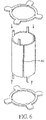
- FIG. 8 is a perspective exploded view of a stator structure of a seventh embodiment of the present invention.
- the invention provides a stator structure including a first stator part and a second stator part.
- the first and second stator parts are made of the same material and coupled together to form the stator structure with a cylindrical waist post.
- the stator structure may be fabricated by rolling a single silicon steel sheet or telescoping two rolled stator parts.
- FIG. 2A shows a first embodiment of a stator structure of the invention.
- the stator structure includes a first stator part 21 and a second stator part 22 .
- the first and second stator parts 21 and 22 may be formed by the same mold, integrally formed by pressing, or be formed by a single silicon steel piece.
- the first and second stator parts 21 and 22 are shaped to correspond to each other.
- Upper and lower ends of the first and second stator parts 21 and 22 include a plurality of upper salients 211 and 221 and a plurality of lower salients 212 and 222 , respectively.
- a first connecting portion 205 a connects the upper salients 211 and the lower salients 212 to constitute the first stator part 21 .
- a second connecting portion 205 b connects the upper salients 221 and the lower salients 222 to construct the second stator part 22 .
- a protrusion 213 and a recess 214 are disposed on two sides of the first connecting portion 205 a (except sides with salients), respectively.
- a protrusion 223 and a recess 224 are disposed on two sides of the second connecting portion 205 b (except sides with salients), respectively.
- the protrusion 213 and the recess 214 engage the recess 224 and the protrusion 223 , respectively, so that the first and second connecting portion 205 a and 205 b are connected to form a waist post of the stator structure.
- the upper salients 211 of the first stator part 21 and the upper salients 221 of the second stator part 22 are located on a first plane.
- the lower salients 212 of the first stator part 21 and the lower salients 222 of the second stator part 22 are located on a second plane.
- each upper salient 211 is placed between two adjacent lower salients 212 and each upper salient 221 is placed between two adjacent lower salients 222 ; in other words, the upper salients 211 and 221 and the lower salients 212 and 222 are in a staggered arrangement along the axial direction.
- FIG. 3 shows a second embodiment of a stator structure of the invention, which is similar to the first embodiment.
- the first and second stator parts 21 and 22 further include a plurality of upper projections 215 and 225 and a plurality of lower projections 216 and 226 , respectively, for enabling another two stator parts 23 and 24 to telescope thereon.
- Each stator part 23 and 24 has one or several silicon steel pieces stacked together, increasing conduction area and conducting efficiency.
- the stator parts 23 and 24 have openings 230 and 240 , inner surfaces in the openings 230 and 240 , a plurality of notches 232 and 242 formed on the inner surfaces, and a plurality of salients 231 and 241 , respectively.
- the notches 232 and 242 can respectively correspond to the upper projections 215 and 225 and the lower projections 216 and 226 .
- the salients 231 and 241 extend horizontally outward from the openings 230 and 240 .
- the recess 232 and 242 are engaged to the upper projections 215 and 225 and the lower projections 216 and 226 to locate the position.
- the salients 231 and 241 are aligned with the upper salients 211 and 221 and the lower salients 212 and 222 , respectively.
- the stator parts 23 and 24 are fabricated using the same mold, as are the first and second stator parts 21 and 22 . Each stator part is a single piece, thereby reducing manufacturing costs. Further, a coil can be wound around the stator structure of FIG. 3 , as similar to FIG. 2B .
- FIG. 4 shows a third embodiment of a stator structure of the invention, which is similar to the second embodiment except that the first and second stator parts 21 and 22 do not require upper salients 211 and 221 such that a bobbin having a coil wound thereon (not shown) can pass therethrough. Therefore, the stator part 23 is assembled with the first and second stator parts 21 and 22 through the engagement between the upper projections 215 and 225 and the notches 232 . Further, a coil can be wound around the stator structure of FIG. 4 , as similar to FIG. 2B .
- FIG. 5 shows a fourth embodiment of a stator structure of the invention, which is similar to the second embodiment expect that the first and second stator parts 21 and 22 do not require upper salients 211 and 221 and lower salients 212 and 222 such that a bobbin having a coil wound thereon (not shown) can pass therethrough.
- the stator parts 23 and 24 are assembled with the first and second stator parts 21 and 22 by engaging the upper projections 215 and 225 and lower projections 216 and 226 with the notches 232 and 242 , respectively. Further, a coil can be wound around the stator structure of FIG. 5 , as similar to FIG. 2B .
- FIG. 6 shows a fifth embodiment of a stator structure of the invention, which is similar to the fourth embodiment except that the first and second stator parts 21 and 22 are integrally formed by a single silicon steel sheet, rolled to form a cylindrical waist post of the stator structure.
- a gap 61 extending parallel to the axial direction of the waist post is formed for preventing eddy current loss.
- a coil can be wound around the stator structure of FIG. 6 , as similar to FIG. 2B .
- FIG. 7 shows a sixth embodiment of a stator structure of the invention, which is similar to the fifth embodiment except that upper and lower ends of the waist post 710 have upper convexities 711 and lower convexities 712 , aligned with upper projections 713 and lower projections 714 , respectively.
- the upper and lower convexities 711 and 712 are formed by cutting slots on the waist post 710 and then pressing them outward.
- Each stator parts 72 and 73 can include one silicon steel piece or a plurality of silicon steel pieces stacked together.
- the stator parts 72 and 73 further comprise inner surfaces and a plurality of notches 721 and 731 formed thereon.
- the upper and lower projections 713 and 714 pass through the notches 721 and 731 , and the upper and lower convexities 711 and 712 are engaged with the notches 721 and 731 .
- the upper and lower projections 713 and 714 are then bent outward to prevent the stator parts 72 and 73 from separating from the stator part 71 . Further, a coil can be wound around the stator structure of FIG. 7 , as similar to FIG. 2B .
- FIG. 8 shows a seventh embodiment of a stator structure of the invention.
- the stator structure includes a first stator part 81 and a second stator part 82 , and the waist post 813 of the first stator part 81 is telescoped into that of the second stator part 82 .
- the first and second stator parts 81 and 82 are formed by a single silicon piece, respectively.
- a plurality of salients 811 is disposed at the lower fringe of the first stator part 81 , and a plurality of projections 812 is formed on an opposite fringe.
- a plurality of salients 821 and a plurality of notches 822 are alternatively disposed at upper fringe of the second stator part 82 .
- the notches 822 correspond to the projections 812 of the first stator part 81 .
- a plurality of receiving portions 824 is formed at the lower fringe of the second stator part 82 .
- the waist post 813 of the first stator part 81 is disposed inside another waist post 823 of the second stator part 82 to form a multi-layer waist post.
- the salients 811 enter the receiving portions 824 , and the projections 812 are bent outward and engaged with the notches 822 .
- the first and second stator parts 81 and 82 have gaps 815 and 825 extending parallel to the axial direction of the waist post for preventing eddy current loss.
- a coil can be wound around the stator structure of FIG. 8 , as similar to FIG. 2B .
- the parts of the stator structure are made of the same material (e.g. silicon steel) so that they can be assembled in accurate positions without requiring any other positioning elements such as conventional bobbins.
- This can effectively reduce the accumulations of dimensional tolerances for the assembled stator structure.
- manufacturing and assembling the stator structure become convenient and fast.
- the conventional processes of producing the stator structure including machining magnetic bars of iron by turning operations to produce stator parts and then fitting them in with bobbins by forcing them, are not used. Rather, the upper, lower and middle stator parts of the stator structure are single pieces made of the same material.
- the stator structure can create a good magnetic loop.
- the middle stator part has an axial gap to avoid eddy current losses.
- the stator parts can be produced by a common mold, thereby significantly reducing the manufacturing cost and simplifying the manufacturing processes.
Landscapes
- Engineering & Computer Science (AREA)
- Power Engineering (AREA)
- Iron Core Of Rotating Electric Machines (AREA)
Abstract
A stator structure includes at least one stator part having a single rolled steel sheet to serve as a waist post with a gap. A first stator part includes a first engaging portion. A second stator part includes a second engaging portion corresponding to the first engaging portion. The first and second stator parts are of the same material. When the first stator part is assembled with the second stator part, the first engaging portion is engaged with the second engaging portion so as to form the stator structure with a waist post.
Description
This application is a Continuation of U.S. application Ser. No. 10/969,012, filed on Oct. 21, 2004, which issued as U.S. Pat. No. 7,196,448 on Mar. 27, 2007, and for which priority is claimed under 35 U.S.C. § 120; and this application claims priority of Application No. 093110302, filed in Taiwan, R.O.C. on Apr. 14, 2004, under 35 U.S.C. § 119; the entire contents of all are hereby incorporated by reference.
1. Field of the Invention
The present invention relates to a composite stator structure and in particular to a stator structure in a cooling fan.
2. Brief Discussion of the Related Art
An object of the invention is to provide a stator structure with reduced size, easily manufactured, and improved magnetic characteristics in a cooling fan.
Another object of the invention is to provide a stator structure which is integral formed with same material, assembling rapidly and locating precisely.
Embodiments of a stator structure comprise a first stator part and a second stator part. The first stator part comprises a first engaging portion, and the second stator part comprises a second engaging portion corresponding to the first engaging portion. The first and second stator parts are of the same material. When the first stator part connects to the second stator part, the first engaging portion connects to the second engaging portion to form a waist post.
Preferably, the first and second stator parts further comprise a plurality of salients, respectively, extending horizontally outward with respect to an axial line of the waist post. Further, The first engaging portion has a recess and the second engaging portion has a protrusion corresponding to the recess.
The first and second stator parts may further comprise a plurality of upper and lower salients, respectively, formed on two opposite ends of the first and second engaging portions. The upper salients of the first and second stator parts are located on a plane. The lower salients of the first and second stator parts are located on another plane. The upper salients and the lower salients are in a staggered arrangement.
Preferably, the first and second stator parts may be formed by the same mold and integrally formed by injection molding.
The first and second stator parts may further comprise a plurality of projections extending out from a fringe thereof, respectively.
The stator structure may further comprise a third stator part connected to ends of the first and second stator parts. The third stator part may be constructed by one or more silicon steel piece comprising an opening, an inner surface in the opening, and a plurality of notches formed on the inner surface, and the projections extend through the notches out of the opening and are bent outwards.
Otherwise, the stator structure may further comprise a third stator part and a fourth stator part connected to ends of the first and second stator parts, respectively. The third and fourth stator parts may be formed by the same mold and integrally formed by injection molding, or may be constructed by one or more silicon steel piece stacked.
The stator structure may further comprise an insulation layer covered the stator structure, or a bobbin disposed on the waist post so that a coil is wound thereon.
The invention also provides a stator structure comprising a first stator part and a second stator part. The first stator part is formed by rolling a single silicon steel sheet to form a waist post. The second stator part is constructed by one or more silicon steel piece stacked. The second stator part connects to at least one end of the first stator part.
The first stator part may comprise a plurality of salients extending horizontally outward with respect to an axial line of the waist post. A gap extending parallel to the axial direction of the waist post is formed.
The first stator part may comprise a plurality of projections extending out from a fringe thereof. The second stator part may comprise an opening, an inner surface in the opening, and a plurality of notches formed on the inner surface. The projections extend through the notches out of the opening and are bent outward.
Moreover, the first stator part may comprise a plurality of convexities formed on the waist post according to the notches on the inner surface.
The invention further provides a stator structure comprising a first stator part formed by rolling a single silicon steel sheet and a second stator part formed by rolling another single silicon steel sheet. The first and second stator parts are assembled with each other to form a multi-layer waist post.
The first stator part may comprise a plurality of receiving portions and notches formed on two opposite ends thereof, respectively. The second stator part may comprise a plurality of salients and projections formed on two opposite ends thereof, respectively. When the first stator part is assembled with the second stator part, the salients are coupled to the receiving portions, and the projections pass through the notches and are bent outward.
Further scope of the applicability of the present invention will become apparent from the detailed description given hereinafter. However, it should be understood that the detailed description and specific examples, while indicating preferred embodiments of the invention, are given by way of illustration only, since various changes and modifications within the spirit and scope of the invention will become apparent to those skilled in the art from this detailed description.
The present invention will become more fully understood from the subsequent detailed description and the accompanying drawings, which are given by way of illustration only, and thus are not limitative of the present invention, and wherein:
The invention provides a stator structure including a first stator part and a second stator part. The first and second stator parts are made of the same material and coupled together to form the stator structure with a cylindrical waist post. Furthermore, the stator structure may be fabricated by rolling a single silicon steel sheet or telescoping two rolled stator parts.
An insulator sheathes the first and second stator parts 21 and 22, and coil 20 is wound therearound, as shown in FIG. 2B .
As mentioned above, the parts of the stator structure are made of the same material (e.g. silicon steel) so that they can be assembled in accurate positions without requiring any other positioning elements such as conventional bobbins. This can effectively reduce the accumulations of dimensional tolerances for the assembled stator structure. Also, manufacturing and assembling the stator structure become convenient and fast. Furthermore, the conventional processes of producing the stator structure, including machining magnetic bars of iron by turning operations to produce stator parts and then fitting them in with bobbins by forcing them, are not used. Rather, the upper, lower and middle stator parts of the stator structure are single pieces made of the same material. Thus, the stator structure can create a good magnetic loop. Furthermore, the middle stator part has an axial gap to avoid eddy current losses. Furthermore, the stator parts can be produced by a common mold, thereby significantly reducing the manufacturing cost and simplifying the manufacturing processes.
While the invention has been described by way of example and in terms of preferred embodiments, it is to be understood that the invention is not limited thereto. On the contrary, it is intended to cover various modifications and similar arrangements as would be apparent to those skilled in the art. Therefore, the scope of the appended claims should be accorded the broadest interpretation so as to encompass all such modifications and similar arrangements.
Claims (15)
1. A stator structure, comprising:
at least one stator part having a single rolled silicon steel sheet as a waist post with a gap, and a plurality of projections formed on two opposite ends thereof; and
another two stator parts, each having an opening with a plurality of notches formed on an inner surface thereof;
wherein a coil is directly wound and extends axially around the waist post, the projections pass through the notches and are securely fit with the notches, respectively.
2. The stator structure as claimed in claim 1 , further comprising a plurality of stator parts of the same material, coupled to each other to form the waist post.
3. The stator structure as claimed in claim 2 , wherein each stator part has at least one recess and at least one protrusion to be assembled with another stator parts, respectively.
4. The stator structure as claimed in claim 2 , wherein each of the plurality of stator parts is formed by a single silicon steel piece.
5. The stator structure as claimed in claim 4 , wherein the plurality of stator parts are telescoped together to form a multi-layer waist post.
6. The stator structure as claimed in claim 5 , wherein the plurality of stator parts include a first stator part and a second stator part, the first stator part having a plurality of receiving portions and the second stator part having a plurality of salients, wherein when the first stator part is assembled with the second stator part, the salients are coupled to the receiving portions.
7. The stator structure as claimed in claim 1 , wherein the stator part has a plurality of convexities formed on the waist post and corresponds to the notches.
8. The stator structure as claimed in claim 7 , wherein each of the another two stator parts is constructed by one or more silicon steel pieces stacked together.
9. The stator structure as claimed in claim 8 , wherein after the plurality of projections pass through the notches, the projections are bent outward.
10. The stator structure as claimed in claim 1 , wherein the plurality of stator parts have a plurality of salients extending radially outward from the waist post.
11. A stator structure, comprising:
a first stator part having a first connecting portion;
a second stator part having a second connecting portion;
a plurality of projections formed on two opposite ends of the first stator part and the second stator part; and
another two stator parts, each having an opening with a plurality of notches formed on an inner surface thereof;
wherein the first and second stator parts have the same shapes and are of the same material, the first connecting portion contacts the second connecting portion, and the first connecting portion is coupled with the second connecting portion to form a waist post of the stator structure for allowing a coil to be directly wound and to extend axially thereon, and the projections pass through the notches and are securely fit with the notches, respectively.
12. A stator structure, comprising:
a first stator part having a single rolled silicon steel sheet with a waist post, and having a plurality of projections formed on two opposite ends thereof; and
a second stator part having a silicon steel piece to be assembled with an end of the first stator part, and having an opening with a plurality of notches formed on an inner surface of the opening;
wherein a coil is directly wound and extends axially around the waist post, the projections pass through the notches and are securely fit with the notches, respectively.
13. The stator structure as claimed in claim 12 , wherein after the plurality of projections pass through the plurality of notches, the projections are bent outward, and the first and second stator parts have a plurality of salients extending radially outward from the waist post.
14. The stator structure as claimed in claim 12 , wherein the first stator part has a plurality of convexities formed on the waist post, and the convexities correspond to the notches.
15. A stator structure, comprising:
a first stator part having a single rolled silicon steel sheet;
a second stator part having another single rolled silicon steel sheet;
a plurality of projections formed on two opposite ends of the first stator part and the second stator part; and
another two stator parts, each having an opening with a plurality of notches formed on an inner surface thereof;
wherein the first and second stator parts are assembled with each other to form a waist post; a coil is directly wound and extends axially around the waist post, and the projections pass through the notches and are securely fit with the notches, respectively.
Priority Applications (1)
| Application Number | Priority Date | Filing Date | Title |
|---|---|---|---|
| US11/714,258 US7479724B2 (en) | 2004-04-14 | 2007-03-06 | Stator structure |
Applications Claiming Priority (4)
| Application Number | Priority Date | Filing Date | Title |
|---|---|---|---|
| TW93110302 | 2004-04-14 | ||
| TW093110302A TWI290409B (en) | 2004-04-14 | 2004-04-14 | Composite stator structure of motor |
| US10/969,012 US7196448B2 (en) | 2004-04-14 | 2004-10-21 | Stator structure |
| US11/714,258 US7479724B2 (en) | 2004-04-14 | 2007-03-06 | Stator structure |
Related Parent Applications (1)
| Application Number | Title | Priority Date | Filing Date |
|---|---|---|---|
| US10/969,012 Continuation US7196448B2 (en) | 2004-04-14 | 2004-10-21 | Stator structure |
Publications (2)
| Publication Number | Publication Date |
|---|---|
| US20070159014A1 US20070159014A1 (en) | 2007-07-12 |
| US7479724B2 true US7479724B2 (en) | 2009-01-20 |
Family
ID=35095571
Family Applications (2)
| Application Number | Title | Priority Date | Filing Date |
|---|---|---|---|
| US10/969,012 Expired - Lifetime US7196448B2 (en) | 2004-04-14 | 2004-10-21 | Stator structure |
| US11/714,258 Expired - Fee Related US7479724B2 (en) | 2004-04-14 | 2007-03-06 | Stator structure |
Family Applications Before (1)
| Application Number | Title | Priority Date | Filing Date |
|---|---|---|---|
| US10/969,012 Expired - Lifetime US7196448B2 (en) | 2004-04-14 | 2004-10-21 | Stator structure |
Country Status (4)
| Country | Link |
|---|---|
| US (2) | US7196448B2 (en) |
| JP (1) | JP2005304288A (en) |
| DE (1) | DE102004053097A1 (en) |
| TW (1) | TWI290409B (en) |
Cited By (2)
| Publication number | Priority date | Publication date | Assignee | Title |
|---|---|---|---|---|
| US20100314964A1 (en) * | 2009-06-16 | 2010-12-16 | Eta Sa Manufacture Horlogere Suisse | Electro-mechanical transducer of small dimensions, in particular a timepiece generator |
| WO2024150092A1 (en) * | 2023-01-11 | 2024-07-18 | Dyson Technology Limited | Stator member and method of forming a stator member |
Families Citing this family (9)
| Publication number | Priority date | Publication date | Assignee | Title |
|---|---|---|---|---|
| TWI290409B (en) * | 2004-04-14 | 2007-11-21 | Delta Electronics Inc | Composite stator structure of motor |
| US7986065B2 (en) * | 2008-06-04 | 2011-07-26 | Robert Bosch Gmbh | Sealed rolled pole housing for an electric motor |
| TWI455450B (en) * | 2009-01-16 | 2014-10-01 | Foxnum Technology Co Ltd | Assembly mechanism for stator of motor and assembly method for the same |
| EP2466723A1 (en) * | 2010-12-20 | 2012-06-20 | Cyoris Ag | Transversal flow machine |
| FR3005807B1 (en) * | 2013-05-14 | 2015-05-15 | Sagem Defense Securite | PREDETERMINED INDUCTOR STATOR, ELECTRIC MOTOR COMPRISING SUCH STATOR AND METHOD FOR MANUFACTURING SUCH STATOR |
| TWI619332B (en) * | 2016-04-15 | 2018-03-21 | 東元電機股份有限公司 | Combination type motor stator and method for manufacturing the same |
| FR3089712B1 (en) * | 2018-12-11 | 2023-03-10 | Ifp Energies Now | Electric machine stator with a ring formed by a plurality of stator segments |
| ES2914811T3 (en) * | 2019-05-27 | 2022-06-16 | Magnax Bv | Stator for an axial flow machine |
| DE102021205499A1 (en) | 2021-03-24 | 2022-09-29 | Brose Fahrzeugteile Se & Co. Kommanditgesellschaft, Bamberg | Drive device and stator assembly therefor |
Citations (20)
| Publication number | Priority date | Publication date | Assignee | Title |
|---|---|---|---|---|
| US2701318A (en) | 1952-11-22 | 1955-02-01 | Gen Electric | Dynamoelectric machine casing |
| US3463955A (en) | 1966-11-14 | 1969-08-26 | Allis Chalmers Mfg Co | Laminated core |
| US3495113A (en) * | 1967-02-21 | 1970-02-10 | Tri Tech | Electric rotating machinery having one stator pole on each pole piece |
| US3521100A (en) | 1969-03-26 | 1970-07-21 | Baldor Electric Co | D.c. motor with cast main yoke and laminated interpole yoke and method of forming |
| JPS5541168A (en) | 1978-09-16 | 1980-03-22 | Shinko Electric Co Ltd | Rotary electric machine |
| US4496869A (en) | 1982-12-08 | 1985-01-29 | Tobishi Industries Ltd. | Small shaded-pole motor |
| US4775813A (en) * | 1986-03-21 | 1988-10-04 | U.S. Philips Corporation | Electric motor having formed stator sections with coplanar teeth |
| US4851729A (en) | 1986-03-17 | 1989-07-25 | Johnson Electric Industrial Manufactory, Limited | Electric motor |
| US4891567A (en) | 1987-07-16 | 1990-01-02 | Minebea Co., Ltd. | Brushless DC motor having an outer rotor |
| US5457350A (en) * | 1992-07-29 | 1995-10-10 | Kabushiki Kaisha Sankyo Seiki Seisakusho | Laminated core of rotating electric machine |
| US5859487A (en) | 1997-05-30 | 1999-01-12 | Delta Electronics, Inc. | Stator structure of motor and its forming method |
| US5945765A (en) | 1998-01-28 | 1999-08-31 | Chen; Shung-Hsiung | Interior stator assembly for a brushless motor with exciting sheets for enhancing rotor-driving force |
| US6285108B1 (en) | 1999-03-16 | 2001-09-04 | Sunonwealth Electric Machine Industry Co., Ltd. | Brushless DC motor |
| US6538357B2 (en) | 2001-04-03 | 2003-03-25 | Sunonwealth Electric Machine Industry Co., Ltd. | Direct current brushless motor of radial air-gap |
| US20040036374A1 (en) * | 2000-04-19 | 2004-02-26 | Noble Ernest John | Method of producing stator windings |
| US6759786B2 (en) * | 2001-08-30 | 2004-07-06 | Sunonwealth Electric Machine Industry Co., Ltd. | Stator of a brushless direct current motor and a method for making it |
| US6847285B2 (en) | 2001-08-13 | 2005-01-25 | General Electric Company | Interlock tabs for laminations |
| US6853101B2 (en) * | 2000-09-29 | 2005-02-08 | Delta Electronics Inc. | Stator structure of rotary device and its forming method |
| US7095142B2 (en) * | 2004-05-21 | 2006-08-22 | H&S Autoshot Manufacturing | Pneumatic tool with integrated electricity generator |
| US7196448B2 (en) * | 2004-04-14 | 2007-03-27 | Delta Electronics, Inc. | Stator structure |
-
2004
- 2004-04-14 TW TW093110302A patent/TWI290409B/en not_active IP Right Cessation
- 2004-10-21 US US10/969,012 patent/US7196448B2/en not_active Expired - Lifetime
- 2004-11-03 DE DE102004053097A patent/DE102004053097A1/en not_active Ceased
-
2005
- 2005-03-17 JP JP2005077721A patent/JP2005304288A/en active Pending
-
2007
- 2007-03-06 US US11/714,258 patent/US7479724B2/en not_active Expired - Fee Related
Patent Citations (20)
| Publication number | Priority date | Publication date | Assignee | Title |
|---|---|---|---|---|
| US2701318A (en) | 1952-11-22 | 1955-02-01 | Gen Electric | Dynamoelectric machine casing |
| US3463955A (en) | 1966-11-14 | 1969-08-26 | Allis Chalmers Mfg Co | Laminated core |
| US3495113A (en) * | 1967-02-21 | 1970-02-10 | Tri Tech | Electric rotating machinery having one stator pole on each pole piece |
| US3521100A (en) | 1969-03-26 | 1970-07-21 | Baldor Electric Co | D.c. motor with cast main yoke and laminated interpole yoke and method of forming |
| JPS5541168A (en) | 1978-09-16 | 1980-03-22 | Shinko Electric Co Ltd | Rotary electric machine |
| US4496869A (en) | 1982-12-08 | 1985-01-29 | Tobishi Industries Ltd. | Small shaded-pole motor |
| US4851729A (en) | 1986-03-17 | 1989-07-25 | Johnson Electric Industrial Manufactory, Limited | Electric motor |
| US4775813A (en) * | 1986-03-21 | 1988-10-04 | U.S. Philips Corporation | Electric motor having formed stator sections with coplanar teeth |
| US4891567A (en) | 1987-07-16 | 1990-01-02 | Minebea Co., Ltd. | Brushless DC motor having an outer rotor |
| US5457350A (en) * | 1992-07-29 | 1995-10-10 | Kabushiki Kaisha Sankyo Seiki Seisakusho | Laminated core of rotating electric machine |
| US5859487A (en) | 1997-05-30 | 1999-01-12 | Delta Electronics, Inc. | Stator structure of motor and its forming method |
| US5945765A (en) | 1998-01-28 | 1999-08-31 | Chen; Shung-Hsiung | Interior stator assembly for a brushless motor with exciting sheets for enhancing rotor-driving force |
| US6285108B1 (en) | 1999-03-16 | 2001-09-04 | Sunonwealth Electric Machine Industry Co., Ltd. | Brushless DC motor |
| US20040036374A1 (en) * | 2000-04-19 | 2004-02-26 | Noble Ernest John | Method of producing stator windings |
| US6853101B2 (en) * | 2000-09-29 | 2005-02-08 | Delta Electronics Inc. | Stator structure of rotary device and its forming method |
| US6538357B2 (en) | 2001-04-03 | 2003-03-25 | Sunonwealth Electric Machine Industry Co., Ltd. | Direct current brushless motor of radial air-gap |
| US6847285B2 (en) | 2001-08-13 | 2005-01-25 | General Electric Company | Interlock tabs for laminations |
| US6759786B2 (en) * | 2001-08-30 | 2004-07-06 | Sunonwealth Electric Machine Industry Co., Ltd. | Stator of a brushless direct current motor and a method for making it |
| US7196448B2 (en) * | 2004-04-14 | 2007-03-27 | Delta Electronics, Inc. | Stator structure |
| US7095142B2 (en) * | 2004-05-21 | 2006-08-22 | H&S Autoshot Manufacturing | Pneumatic tool with integrated electricity generator |
Cited By (3)
| Publication number | Priority date | Publication date | Assignee | Title |
|---|---|---|---|---|
| US20100314964A1 (en) * | 2009-06-16 | 2010-12-16 | Eta Sa Manufacture Horlogere Suisse | Electro-mechanical transducer of small dimensions, in particular a timepiece generator |
| US8179012B2 (en) * | 2009-06-16 | 2012-05-15 | ETA SA Manufacture Horlogére Suisse | Electro-mechanical transducer of small dimensions, in particular a timepiece generator |
| WO2024150092A1 (en) * | 2023-01-11 | 2024-07-18 | Dyson Technology Limited | Stator member and method of forming a stator member |
Also Published As
| Publication number | Publication date |
|---|---|
| US20050231059A1 (en) | 2005-10-20 |
| TW200534563A (en) | 2005-10-16 |
| JP2005304288A (en) | 2005-10-27 |
| DE102004053097A1 (en) | 2005-11-17 |
| US20070159014A1 (en) | 2007-07-12 |
| TWI290409B (en) | 2007-11-21 |
| US7196448B2 (en) | 2007-03-27 |
Similar Documents
| Publication | Publication Date | Title |
|---|---|---|
| US7479724B2 (en) | Stator structure | |
| KR101070997B1 (en) | Stator of motor for compressor | |
| US6580193B2 (en) | Rotary electric machine and manufacturing method therefor | |
| US20030057796A1 (en) | Modularized stator | |
| US8222791B2 (en) | Alignment of segmented stators for electric machines | |
| US9614406B2 (en) | Wedge for stator having overmolded insulation | |
| US8946964B1 (en) | Modular windings for an electric machine | |
| KR100585691B1 (en) | Stator of Bieldish Motor and its manufacturing method | |
| US7098565B2 (en) | Core-coil assembly of motor and manufacturing method thereof | |
| JPWO2019142289A1 (en) | Electric motor and air conditioner | |
| US6670736B2 (en) | Insulating jacket structure of a stator of a direct current motor | |
| WO2005086318A1 (en) | Armature core for dynamo-electric machine | |
| JP2010207028A (en) | Stator | |
| EP1263115B1 (en) | Claw-pole type stepping motor | |
| CN109546832B (en) | Brushless direct current motor and double-clutch transmission thereof | |
| KR100518012B1 (en) | Structure of stator assembly for linear motor | |
| US7084544B2 (en) | Brushless DC motor | |
| JP4411950B2 (en) | Electric motor stator, manufacturing method thereof, and permanent magnet electric motor using the stator | |
| JP2003164080A (en) | Armature of rotating electric machine and method of manufacturing the same | |
| JP2008104288A (en) | Capacitor motor and manufacturing method thereof | |
| CN109274237B (en) | Outer rotor motor and washing machine with same | |
| JP3603128B2 (en) | Winding method of salient pole type rotor and salient pole type rotor | |
| JP2899440B2 (en) | Motor stator core | |
| JPH0654471A (en) | Rotating machine armature | |
| US5568000A (en) | Multiple pole, shaded pole subfractional-horsepower induction motor |
Legal Events
| Date | Code | Title | Description |
|---|---|---|---|
| STCF | Information on status: patent grant |
Free format text: PATENTED CASE |
|
| FPAY | Fee payment |
Year of fee payment: 4 |
|
| FPAY | Fee payment |
Year of fee payment: 8 |
|
| FEPP | Fee payment procedure |
Free format text: MAINTENANCE FEE REMINDER MAILED (ORIGINAL EVENT CODE: REM.); ENTITY STATUS OF PATENT OWNER: LARGE ENTITY |
|
| LAPS | Lapse for failure to pay maintenance fees |
Free format text: PATENT EXPIRED FOR FAILURE TO PAY MAINTENANCE FEES (ORIGINAL EVENT CODE: EXP.); ENTITY STATUS OF PATENT OWNER: LARGE ENTITY |
|
| STCH | Information on status: patent discontinuation |
Free format text: PATENT EXPIRED DUE TO NONPAYMENT OF MAINTENANCE FEES UNDER 37 CFR 1.362 |
|
| FP | Lapsed due to failure to pay maintenance fee |
Effective date: 20210120 |