US7466943B2 - Image forming apparatus comprising a developer roller - Google Patents
Image forming apparatus comprising a developer roller Download PDFInfo
- Publication number
- US7466943B2 US7466943B2 US11/399,622 US39962206A US7466943B2 US 7466943 B2 US7466943 B2 US 7466943B2 US 39962206 A US39962206 A US 39962206A US 7466943 B2 US7466943 B2 US 7466943B2
- Authority
- US
- United States
- Prior art keywords
- developer roller
- image
- forming apparatus
- rotation speed
- image forming
- Prior art date
- Legal status (The legal status is an assumption and is not a legal conclusion. Google has not performed a legal analysis and makes no representation as to the accuracy of the status listed.)
- Expired - Fee Related, expires
Links
- 238000011161 development Methods 0.000 claims abstract description 88
- 230000015572 biosynthetic process Effects 0.000 claims abstract description 64
- 238000010438 heat treatment Methods 0.000 claims description 4
- 230000006866 deterioration Effects 0.000 abstract description 17
- 238000003860 storage Methods 0.000 description 22
- 238000012546 transfer Methods 0.000 description 15
- 238000013019 agitation Methods 0.000 description 13
- 238000000034 method Methods 0.000 description 13
- 238000004140 cleaning Methods 0.000 description 7
- 238000010586 diagram Methods 0.000 description 7
- 230000005611 electricity Effects 0.000 description 7
- 238000012545 processing Methods 0.000 description 7
- 229910021417 amorphous silicon Inorganic materials 0.000 description 6
- 230000000694 effects Effects 0.000 description 6
- 238000006243 chemical reaction Methods 0.000 description 5
- 150000002500 ions Chemical class 0.000 description 5
- 230000001186 cumulative effect Effects 0.000 description 4
- 238000011835 investigation Methods 0.000 description 3
- 230000003287 optical effect Effects 0.000 description 3
- CBENFWSGALASAD-UHFFFAOYSA-N Ozone Chemical compound [O-][O+]=O CBENFWSGALASAD-UHFFFAOYSA-N 0.000 description 2
- 229910052782 aluminium Inorganic materials 0.000 description 2
- XAGFODPZIPBFFR-UHFFFAOYSA-N aluminium Chemical compound [Al] XAGFODPZIPBFFR-UHFFFAOYSA-N 0.000 description 2
- 230000005540 biological transmission Effects 0.000 description 2
- 230000000052 comparative effect Effects 0.000 description 2
- 230000006870 function Effects 0.000 description 2
- 230000009191 jumping Effects 0.000 description 2
- 238000005192 partition Methods 0.000 description 2
- 230000001737 promoting effect Effects 0.000 description 2
- 230000000284 resting effect Effects 0.000 description 2
- 230000003746 surface roughness Effects 0.000 description 2
- 238000012360 testing method Methods 0.000 description 2
- 235000014676 Phragmites communis Nutrition 0.000 description 1
- 239000000969 carrier Substances 0.000 description 1
- 239000003638 chemical reducing agent Substances 0.000 description 1
- 239000006185 dispersion Substances 0.000 description 1
- 238000009826 distribution Methods 0.000 description 1
- 230000005684 electric field Effects 0.000 description 1
- 230000007613 environmental effect Effects 0.000 description 1
- 230000007774 longterm Effects 0.000 description 1
- 238000004519 manufacturing process Methods 0.000 description 1
- 239000000463 material Substances 0.000 description 1
- 238000005259 measurement Methods 0.000 description 1
- 229910052751 metal Inorganic materials 0.000 description 1
- 239000002184 metal Substances 0.000 description 1
- 238000012986 modification Methods 0.000 description 1
- 230000004048 modification Effects 0.000 description 1
- 238000002360 preparation method Methods 0.000 description 1
- 230000000630 rising effect Effects 0.000 description 1
- 239000007787 solid Substances 0.000 description 1
- 238000000638 solvent extraction Methods 0.000 description 1
- YDLQKLWVKKFPII-UHFFFAOYSA-N timiperone Chemical compound C1=CC(F)=CC=C1C(=O)CCCN1CCC(N2C(NC3=CC=CC=C32)=S)CC1 YDLQKLWVKKFPII-UHFFFAOYSA-N 0.000 description 1
- 229950000809 timiperone Drugs 0.000 description 1
- 230000000007 visual effect Effects 0.000 description 1
- 239000002699 waste material Substances 0.000 description 1
Images


Classifications
-
- G—PHYSICS
- G03—PHOTOGRAPHY; CINEMATOGRAPHY; ANALOGOUS TECHNIQUES USING WAVES OTHER THAN OPTICAL WAVES; ELECTROGRAPHY; HOLOGRAPHY
- G03G—ELECTROGRAPHY; ELECTROPHOTOGRAPHY; MAGNETOGRAPHY
- G03G15/00—Apparatus for electrographic processes using a charge pattern
- G03G15/75—Details relating to xerographic drum, band or plate, e.g. replacing, testing
- G03G15/751—Details relating to xerographic drum, band or plate, e.g. replacing, testing relating to drum
-
- G—PHYSICS
- G03—PHOTOGRAPHY; CINEMATOGRAPHY; ANALOGOUS TECHNIQUES USING WAVES OTHER THAN OPTICAL WAVES; ELECTROGRAPHY; HOLOGRAPHY
- G03G—ELECTROGRAPHY; ELECTROPHOTOGRAPHY; MAGNETOGRAPHY
- G03G15/00—Apparatus for electrographic processes using a charge pattern
- G03G15/06—Apparatus for electrographic processes using a charge pattern for developing
- G03G15/08—Apparatus for electrographic processes using a charge pattern for developing using a solid developer, e.g. powder developer
- G03G15/0806—Apparatus for electrographic processes using a charge pattern for developing using a solid developer, e.g. powder developer on a donor element, e.g. belt, roller
Definitions
- the invention relates to an image forming apparatus, such as a copier, a facsimile, a printer, or the like, provided with a development unit that agitates and conveys a toner inside the unit and then supplies it to a developer roller, and more specifically to a drive control method of the development unit.
- amorphous silicon (hereinafter, referred to as a-Si) photoconductive drums have been widely used as image carriers for an image forming apparatus using an electrophotographic process.
- the a-Si photoconductive drum is an excellent image carrier with a high degree of hardness, excellent durability, a capability of maintaining high image quality with little deterioration in its properties as a photoconductor even after its long-term use, which requires low running costs, is easy to handle, and provides a high level of environmental safety.
- Such an image forming apparatus using an a-Si photoconductive drum is known to have a property that easily causes image blurring. That is, charging the photoconductive drum by using a charge unit results in ozone generation caused by discharge from the charge unit. This ozone decomposes a component in the air, whereby an ion product, such as NOx, SOx, or the like, is generated. Due to its water-soluble nature, this ion product adheres to the photoconductive drum and enters into a structure formed, with a roughness of approximately 0.1 ⁇ m, on the photoconductive drum surface, so that the ion product cannot be removed by a cleaning system used in a general purpose machine.
- ion product such as NOx, SOx, or the like
- this ion product intakes moisture contained in the air, thereby causing a reduction in the resistance of the photoconductive drum surface.
- lateral charge flow occurs at an edge part of an electrostatic latent image formed on the photoconductive drum surface, thus causing image blurring.
- FIG. 6 is a schematic diagram showing the configuration of an image formation part of a conventional image forming apparatus.
- a charge part 42 disposed along the rotation direction of a photoconductive drum 41 (an arrow A direction) in the image formation part 32 are: a charge part 42 , an image writing part (laser scan unit) 43 , a development unit 21 , a transfer part 45 , a cleaning part 46 , and an electricity removing device 48 .
- the photoconductive drum 41 is, for example, formed by laying a photosensitive layer of a-Si on an aluminum drum, and is configured to have its surface charged by the charge part 42 . Then, on the surface receiving a laser beam from the image writing part 43 to be described later, an electrostatic latent image is formed which is charged attenuatedly.
- the charge part (charger) 42 charges the surface of the photoconductive drum 41 through its discharge (for example, corona discharge) which is achieved by, for example, being supplied with a high voltage using a thin wire or the like as an electrode.
- the image writing part (LSU) 43 irradiates the photoconductive drum 41 with an optical beam (for example, laser beam) to thereby form an electrostatic latent image on the surface of the photoconductive drum 41 .
- the development unit 21 is provided with a developer roller 21 a that is so arranged as to oppose the photoconductive drum 41 , and, by using a developer roller 21 a , has a toner stored therein adhere to the electrostatic latent image on the photoconductive drum 41 to thereby form a toner image.
- the toner stored in the development unit 21 is, for example, a two-component toner, composed of a toner component and a carrier, and a one-toner component toner composed of a toner component only.
- the cleaning part 46 removes a toner remaining on the surface of the photoconductive drum 41 (residual toner) after a toner image is shifted (transferred) to a sheet, and is composed of, for example, a rubbing roller 11 which is brought by a spring 7 into line contact with the photoconductive drum 41 in the longitudinal direction thereof, a cleaning blade 12 , and the like.
- the electricity removing device 48 exposes the surface of the photoconductive drum 41 to, for example, an LED or the like to thereby remove the surface potential after the toner image is transferred.
- the electrostatic latent image is recorded by the image writing part 43 onto the photoconductive drum 41 uniformly charged by the charge part 42 , then this electrostatic latent image is transformed into a visible toner image by the development unit 21 through reversal development, and then the toner image is transferred onto a sheet 10 by the transfer part 45 .
- the toner not transferred by the transfer part 45 is removed as a residual toner from the surface of the photoconductive drum 41 by the cleaning part 46 , and the removed residual toner is transferred by a toner collector, such as a collecting screw 13 or the like, to a waste bottle, not shown.
- a heater 14 is arranged in the photoconductive drum 41 . Through electricity distribution to this heater 14 , an energy that separates the moisture taken in by the ion product is provided, thereby suppressing a reduction in the resistance of the photoconductive drum 41 surface under high-humidity environments.
- FIG. 7 is an enlarged sectional view of a conventional development unit, with the photoconductive drum 41 flipped horizontally from the one shown in FIG. 6 .
- the development unit 21 is configured to include a casing 5 , a cover 6 , a first agitation screw 7 , a second agitation screw 8 , the developer roller 21 a, and a control blade 22 .
- the casing 5 stores a toner, and is formed by partitioning, by the partition plate 9 integrated therewith, a first storage chamber 15 and a second storage chamber 16 . In this first storage chamber 15 , the first agitation screw 7 is disposed, while the second agitation screw 8 is disposed in the second storage chamber 16 .
- the first agitation screw 7 conveys a toner or the like stored in the first storage chamber 15 while agitating it and leads it to the second storage chamber 16 .
- the second agitation screw 8 conveys the toner or the like conveyed to the second storage chamber 16 while agitating it and supplies it to the developer roller 21 a.
- the partition plate 9 does not exist, permitting toner reception and delivery between the first agitation screw 7 and the second agitation screw 8 .
- the first agitation screw 7 and the second agitation screw 8 are configured to have helical blades 7 b and 8 b provided around their respective centers, i.e., spindles 7 a and 8 a, and are rotatably supported in the casing 5 in parallel to each other.
- a magnetic field generating member 23 is Fixed, which has six magnetic poles 23 a to 23 f composed of N poles 23 a , 23 c , and 23 e and S poles 23 b , 23 d , and 23 f .
- the N pole 23 a of the magnetic field generating member 23 opposes the control blade 22 ; thus, the use of a non-magnetic body or a magnetic body of an S pole as the control blade 22 generates a magnetic field in the direction (direction of an arrow C) attracted to a control part 24 .
- This magnetic field causes the toner to rise in a brush like form between the control blade 22 and the developer roller 21 a. Then, rotation of the developer roller 21 a in the direction of an arrow B generates a force acting so as to separate the toner rising in the brush-like form whereby a thin toner layer is formed on the surface of the developer roller 21 a .
- a potential difference between the voltage applied to the developer roller 21 a and the surface potential of the photoconductive drum 41 causes a toner image to be formed onto the surface of the photoconductive drum 41 .
- the developer roller 21 a is so arranged as to oppose, in close proximity to, the photoconductive drum 41 .
- radiant heat from the photoconductive drum 41 causes only the portion of the developer roller 21 a opposing the photoconductive drum 41 to become locally high in temperature.
- the side of the developer roller 21 a opposing the photoconductive drum 41 thermally expands whereby the developer roller 21 a is bent axially (indicated by a solid line of FIG. 8 ).
- a distance d between the photoconductive drum 41 and the developer roller 21 a periodically fluctuates when the developer roller 21 a rotates, thus causing, in particular, periodical image unevenness, such as image fogging on a white paper part, concentration unevenness on a grey image, or the like.
- Patent publication 1 discloses a development unit and an image forming apparatus provided with a structure not having a hollow in at least part of the developer roller by stuffing a filling material having a higher heat conductivity than the developer roller.
- the method of patent publication 1 suffers from problems of more complicated structure of the developer roller, a larger number of components used, and higher manufacturing costs of the developer roller and a development unit using this developer roller.
- Patent publication 2 discloses a method of controlling a heater provided in an image forming apparatus in accordance with the operation mode of each part of the apparatus.
- the method of patent publication 2 does not control the operation of each part of the apparatus in accordance with the operation of the heater, but controls power supply to the heater in accordance with the operation of each part of the apparatus for the purpose of reducing the peak power consumption by the entire apparatus, and thus is not applicable for preventing the deformation of the developer roller.
- the present invention has been made, and it is an object of the invention to provide an image forming apparatus, having a heater provided in a photoconductive drum to prevent image blurring, which prevents deformation of a developer roller caused by the turning on of the heater during a non-image formation period to thereby provide a stable image quality.
- an image forming apparatus including: an image formation part including: a photoconductive drum, a heater for heating the photoconductive drum to a predetermined temperature, and a development unit for forming a toner image onto the surface of the photoconductive drum in accordance with an electrostatic latent image by rotating a developer roller so arranged as to oppose the photoconductive drum; a driver for driving the image formation part; and a controller for controlling driving of the driver, in which the controller rotates the developer roller at a first rotation speed during an image formation period and rotates the developer roller at a second rotation speed, a speed lower than the first rotation speed, during a non-image formation period while the heater is in use.
- the developer roller continues to rotate at the second rotation speed while the heater is in use, thus eliminating a variation in the temperature of the developer roller in the circumferential direction thereof due to radiant heat of the photoconductive drum heated by the heater, which prevents thermal deformation of the developer roller and thus effectively prevents image fogging, concentration unevenness, and the like.
- the second rotation speed is set lower than the first rotation speed; thus, toner deterioration in the development unit can also be suppressed.
- the development unit is independently driven.
- the developer roller can be rotated at the second rotation speed regardless of driving of other units arranged in the image formation part.
- the driver is connected to the development unit via a clutch.
- the driver includes a first driver for driving the image formation part excluding the development unit and a second driver for driving the development unit.
- the controller intermittently drives the developer roller during the non-image formation period while the heater is in use.
- the developer roller is repeatedly driven at the second rotation speed and stopped, thereby permitting preventing the thermal deformation of the developer roller and also further reducing the cumulative drive time of the development unit.
- conditional formula (1) 5/2 B ⁇ T 1 ⁇ 15 /B (1), where
- T 1 is a drive time of the developer roller per the intermittent driving
- B is the second rotation speed
- conditional formula (2) ( T 1+ T 2)/ T 1 ⁇ B (2), where
- T 1 is a drive time of the developer roller per intermittent driving
- T 2 is a stop time of the developer roller per intermittent driving
- B is the second rotation speed
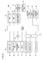
- FIG. 1 is a schematic diagram showing the overall structure of an image forming apparatus of the invention
- FIG. 2 is a block diagram showing the configuration of an image forming apparatus according to a first embodiment of the invention
- FIG. 3 is a block diagram showing the configuration of an image forming apparatus according to a second embodiment of the invention.
- FIG. 4 is a flowchart showing procedures of controlling the driving of a development unit in the image forming apparatus of the invention
- FIG. 5 is a diagram showing effect of reducing image failure when the driving of the development unit is controlled by using the image forming apparatus of the invention
- FIG. 6 is a schematic sectional view showing the structure of an image formation part of a conventional image forming apparatus
- FIG. 7 is a side sectional view of a conventional development unit.
- FIG. 8 is a schematic plan view showing thermal deformation of a developer roller.
- FIG. 1 is a schematic sectional view of an image forming apparatus of the invention. Portions in common to those of FIG. 8 in the conventional example are provided with the same numerals and thus omitted from the description.
- This image forming apparatus (for example, printer) 100 is composed of a photoconductive drum 41 , a charge part 42 , an image writing part 43 , a development unit 21 , a toner container 44 , a transfer part 45 , a cleaning part 46 , a registration roller pair 47 , an electricity removing device 48 , a sheet storage part 51 , a conveyance part 52 , a fixing device 53 , and a sheet discharge part 55 .
- the toner container 44 supplies a toner to the development unit 21 when a toner in the development unit 21 runs out, and also stores reserve toner.
- the registration roller pair 47 once suspends a sheet conveyed from the sheet storage part 51 , and conveys the sheet again in accordance with a timing of image formation performed on the photoconductive drum 41 .
- the sheet storage part 51 stores a sheet (recording medium, such as paper, an OHP, sheet or the like) on which a image (toner image) is finally printed, and also delivers the sheet to the conveyance part 52 , i.e., a sheet path from the sheet storage part 51 to the discharge part 55 .
- the fixing device 53 has a fixing roller pair 54 composed of a heat roller 54 a and a pressure roller 54 b , and transforms a toner image transferred onto a sheet into a stable permanent image, and fuses and fixes the powdered toner image by supplying energy, such as heat, pressure, and the like, by using the fixing roller pair 54 .
- the discharge part 55 stores a sheet that has passed through the fixing device 53 , that is, the sheet with a permanent image printed thereon.
- a sheet is conveyed from the sheet storage part 51 to the registration roller pair 47 via the conveyance part 52 (primary sheet feed).
- an image write signal turns ON, and, based on image data transmitted from a personal computer (PC), not shown, the image writing part 43 emits a laser beam (ray of light) onto the surface of the photoconductive drum 41 to thereby form, onto the surface of the photoconductive drum 41 , an electrostatic latent image based on this image data.
- PC personal computer
- the development unit 21 has toner adhere to the electrostatic latent image (forms a toner image), and also the sheet is delivered from the registration roller pair 47 in accordance with the timing of toner image formation (secondary sheet feed). Then, the toner image is transferred onto the sheet by the transfer part 45 which has been supplied with a predetermined transfer voltage.
- the fixing device 53 applies heat and the like to the sheet with the transferred toner image thereon, whereby the toner image is transformed into a permanent image. Meanwhile, the residual toner on the photoconductive drum 41 and the surface potential thereon are removed by the cleaning part 46 and the electricity removing device 48 , respectively, and then preparation is made for initial charge by the charge part 42 and subsequent formation of a new toner image.
- FIG. 2 is a block diagram showing the configuration of the image forming apparatus according to a first embodiment of the invention. Portions in common with those in FIG. 1 are provided with the same numerals and thus omitted from the description.
- the image forming apparatus 100 is composed of: an image input part 30 , an AD conversion part 31 , an image formation part 32 , a control part 33 , a storage part 34 , an operation panel 35 , a main motor 36 , clutches 37 a to 37 d, the sheet storage part 51 , the conveyance part 52 , and the fixing device 53 .
- the image input part 30 is, in a case where the image forming apparatus 100 is a copier, an image reading part composed of: a scanning optical system loaded with a scanner lamp for illuminating a document at the time of copying and a mirror for changing the optical path of reflected light from the document; a condensing lens for condensing and focusing the reflected light from the document; a CCD for converting the focused image light into an electrical signal; and the like.
- the image input part 30 is, in a case where the image forming apparatus 100 is a printer, a reception part that receives image data transmitted from a personal computer or the like. An image signal inputted by the image input part 30 is converted into a digital signal by the AD conversion part 31 and then delivered to an image memory 60 included in the storage part 34 to be described later.
- the image formation part 32 includes: a heater 14 , the photoconductive drum 41 , the charge part 42 , the image writing part 43 , the development unit 21 , and the transfer part 45 . Based on a digital signal generated by conversion by the AD conversion part 31 , the image formation part 32 forms onto the photoconductive drum 41 an electrostatic latent image, then develops it into a toner image by the development unit 21 , and then transfers the toner image onto a sheet by the transfer part 45 .
- a planer (sheet-type) heater is used, which is fitted along the inner side of the photoconductive drum 41 by making use of elastic property of the sheet. Moreover, the heater 14 undergoes ON/OFF control by a thermostatic reed switch, a thermistor, or the like to be maintained at a fixed temperature when in use.
- the storage part 34 is provided with: the image memory 60 , a RAM 61 , and a ROM 62 .
- the image memory 60 stores an image signal read by the image reading part 30 and digitally converted by the AD conversion part 31 , and delivers the image signal to the control part 33 .
- the RAM 61 and ROM 62 store programs, contents, and the like of processing performed by the control part 33 .
- first rotation speed a rotation speed of the developer roller 21 a during a image formation period
- second rotation speed a rotation speed, slower than the first rotation speed, during a non-image formation period while the heater 14 is in use
- these rotation speeds are delivered to the control part 33 for controlling the driving of the development unit 21 , based on whether or not image formation is performed and whether or not the heater 14 is turned on.
- the operation panel 35 is composed of: an operation part made up of a plurality of operation keys, and a display part for displaying the setting condition, status, and the like of the apparatus, both not shown.
- the operation panel 35 is used for the user to set print condition and the like, and, in a case where the image forming apparatus 100 has a facsimile function, is also used for various settings, such as registration of transmission destinations into the storage part 34 , further reading and writing of the registered transmission destinations, and the like.
- the main motor 36 drives, in accordance with a control signal from the control part 33 , the sheet storage part 51 , the conveyance part 52 , the fixing device 53 , and also the development unit 21 , the photoconductive drum 41 , and the transfer part 45 all the three included in the image formation part 32 , and the like.
- the main motor 36 is connected, via clutches 37 a to 37 d, to the development unit 21 , the photoconductive drum 41 , the transfer part 45 , and the fixing device 53 , and is capable of controlling the driving of the development unit 21 independently from the photoconductive drum 41 , the transfer part 45 , and the like by engaging or disengaging the clutches 37 a to 37 d in accordance with a control signal from the control part 33 .
- the clutches 37 a to 37 d electromagnetic clutches are used which transmit and cut the drive force by the current being turned ON and OFF.
- the control part 33 performs overall control of the image input part 30 , the image formation part 32 , the sheet storage part 51 , the fixing device 53 , the main motor 36 and the clutches 37 a to 37 d controlling the aforementioned parts, in accordance with a set program, and also converts an image signal inputted from the image input part 30 into image data by performing magnification variation processing or gradation processing thereon as appropriate.
- the image writing part 43 based on image data already processed, emits laser light to form a latent image on the photoconductive drum 41 . Further, the control part 33 has a function of controlling the driving of the development unit 21 , based on whether or not an image is formed and whether or not the heater 14 is in use.
- the invention is characterized in that, during the non-image formation period while the heater 14 is in use, the developer roller 21 a rotates at the second rotation speed which is slower than the normal rotation speed (first rotation speed) employed during the image formation period.
- first rotation speed the normal rotation speed employed during the image formation period.
- the second rotation speed which is set lower than the first rotation speed, can control toner deterioration in the development unit 21 more than is achieved when the developer roller 21 a continues to rotate at the first rotation speed.
- the invention is effective, in particular, in application of the development unit 21 employing a one-component development system, which is more susceptible to the heat from the heater 14 due to a smaller gap between the photoconductive drum 41 and the developer roller 21 a compared to a two-component development system, or a non-contact type jumping development system, which is more susceptible to the gap between the photoconductive drum 41 and the developer roller 21 a due to toner dispersion caused by an electric field compared to a contact-type.
- the use of the developer roller 21 a formed of metal, such as aluminum, stainless (SUS), or the like, provides a higher heat conductivity, thus resulting in less risk of local deformation, compared to the use of an elastic roller, such as a rubber roller or the like.
- the first agitation screw 7 and the second agitation screw 8 do not rotate and thus the toner is not agitated more than necessary. This reduces mechanical stress placed on the toner in the development unit 21 , thus even more effectively suppressing the toner deterioration.
- the toner in the development unit 21 does not circulate; thus, the toner temperature around the developer roller 21 a slightly rises. However, once the image formation processing starts and the toner circulates again, the toner temperature immediately becomes uniformized, with no risk of influencing the image formation.
- FIG. 3 is a block diagram showing the configuration of the image forming apparatus according to a second embodiment of the invention.
- the clutches 37 a to 37 d of the first embodiment are not provided, and provided therein instead are: a main motor 36 (first drive) for driving the sheet storage part 51 , the conveyance part 52 , the fixing device 53 , the photoconductive drum 41 , and the transfer part 45 ; and a sub motor 38 (second driver) for driving the development unit 21 .
- the configuration of other portions is common to those in the first embodiment of FIG. 2 , and thus omitted from the description.
- the driving of the development unit 21 can also be controlled independently in this embodiment by turning ON and OFF the driving of the sub motor 38 , thus permitting control of the toner deterioration in the development unit 21 and also permitting effectively preventing image failure caused by the thermal deformation of the developer roller. Moreover, even when the main motor 36 is in a resting state, the development unit 21 can be driven; thus, the running costs of the apparatus can be cut more than the case of the first embodiment.
- the sub motor 38 it is preferable to use a pulse motor, such as a stepping motor or the like, whose speed can easily be controlled.
- FIG. 4 is a flowchart showing image formation operation performed by the image forming apparatus of the first embodiment. In accordance with steps of FIG. 4 while referring to FIG. 2 , procedures of controlling the rotation speed of the developer roller 21 a will be described.
- step S 1 it is determined whether or not printing has started by, for example, operation of the operation panel by the user (step S 1 ). If printing has started, the control part 33 rotates the developer roller 21 a at the first rotation speed stored in the storage part 34 (step S 2 ), and then develops an electrostatic latent image formed on the photoconductive drum 41 based on the print data (step S 3 ). Then, the registration roller pair 47 rotates at a predetermined timing, and a sheet is conveyed to the transfer part 45 in accordance with the image formation timing, whereby a toner image is transferred onto the sheet at the transfer part 45 (step S 4 ). Heat and pressure are then applied to the toner image by the fixing device 53 to thereby transform it into a permanent image, and then the sheet is discharged outside the apparatus.
- step S 5 it is determined whether or not the printing has ended. If the printing is still in progress, the processing returns to step S 2 to repeat the same procedures (step S 2 to S 4 ). On the other hand, if the printing has not yet started in step S 1 , and if the printing has ended in step S 5 , it is determined whether or not the heater 14 is in use (step S 6 ).
- step S 7 the control part 33 disengages the clutch 37 b to 37 d to stop the driving of the respective parts of the apparatus other than the development unit 21 and also rotates the developer roller 21 a at the second rotation speed stored in the storage part 34 by using a speed reducer of the clutch 37 a (step S 7 ). Then, the processing returns to S 1 to repeat the same procedures thereafter (step S 1 to S 6 ). If the heater 14 is not in use in step S 6 , the clutches 37 a to 37 d are disengaged to stop the respective parts of the apparatus including the developer roller 21 a (step S 8 ), and then processing ends.
- the description above refers to the image forming apparatus of the first embodiment in which the development unit 21 can be independently driven by providing the clutches 37 a to 37 d, but this description is also applicable to the image forming apparatus of second embodiment in which the sub motor 38 for driving the development unit 21 is provided independently from the main motor 36 .
- the rotation speed of the sub motor 38 may be controlled based on whether or not the printing has started and whether or not the heater 14 is turned on.
- the drive time per intermittent driving is T 1 (in seconds)
- the outer diameter of the developer roller 21 a is S (in mm)
- the second rotation speed is B (in rpm)
- the outer circumferential length of the developer roller 21 a is S ⁇ (in mm); thus, the circumferential length of the movement of the developer roller 21 a per driving is S ⁇ T 1 ⁇ B/60 (in mm).
- the circumferential length of the movement of the developer roller 21 a per driving with respect to the outer circumferential length of the developer roller 21 a may be set between 15 degrees/360 degrees exclusive but and 90 degrees/360 degrees inclusive.
- the invention is not limited to the embodiments described above, and thus various modifications are permitted without departing from the sprit of the invention.
- the invention is applicable to various image forming apparatuses using a development unit, such as: copiers including digital complex copiers, tandem-type color copiers, analog-type monochrome copiers, and the like; facsimiles; laser printers; and the like.
- the image forming apparatus of the invention By using, as a test machine, the image forming apparatus of the first embodiment that drives the development unit 21 independently from the clutches 37 a to 37 d, a variation in the distance between the photoconductive drum 41 and the developer roller 21 a and the occurrence of image failure have been investigated for a case where the driving of the development unit 21 has been controlled based on whether or not the heater 14 is in use during the non-image formation period (the developer roller 21 a is intermittently driven) (the invention) and a case where the driving of the development unit 21 has not been controlled (the developer roller 21 a is stopped) (comparative example).
- the photoconductive drum used is an amorphous silicon drum having an outer diameter of 84 mm, a film thickness of 35 ⁇ m, a dark potential of 410V, and a bright potential of 20V, with a drum circumferential speed set at 450 mm/sec.
- the development unit employs a magnetic jumping development method, and a developing bias was applied which was obtained by superimposing an AC having a frequency of 2.3 kHz, a Duty of 55%, and a peak to peak voltage of 1.6 kV on a DC 230V.
- the developer roller used has a magnetic field generating member, having a 6-poles structure including N 1 , S 1 , N 2 , S 2 , N 3 , and S 3 , fixed in a roller of SUS316 having an outer diameter of 25 mm and a surface roughness (Rz) of 4.0 ⁇ m.
- the surface roughness Rz of the developer roller is measured by JIS B0601-1994 (ten point average roughness). Setting has been made so that the drive time T 1 per intermittent operation of the developer roller is 1 second, the stopping time thereof is 4 seconds, the rotation speed of the developer roller (second rotation speed) is 5 rpm, the rotation cycle is 60 seconds, and a distance d between the photoconductive drum and the developer roller is 0.32 mm.
- a white solid image was printed after the heater has been kept on for five minutes during the non-image formation period to judge the presence of image fogging by visual check.
- the image forming apparatus which can eliminate a variation in the temperature of the developer roller in the circumferential direction thereof due to radiant heat from the photoconductive drum heated by the heater, thereby effectively preventing the thermal deformation of the developer roller and also suppressing the toner deterioration in the development unit.
- the developer roller performs intermittent operation of repeating driving at the second rotation speed and stopping, which permits preventing the thermal deformation of the developer roller and further reducing the cumulative drive time of the development unit to thereby more effectively suppress the toner deterioration in the development unit.
- setting the rotation angle of the developer roller per intermittent operation between 15 degrees exclusive and 90 degrees inclusive and also setting the rotation cycle of the developer roller at 60 seconds or below provide intermittent operation condition that provides satisfactory effect of preventing the toner deterioration in the development unit and satisfactory effect of preventing the thermal deformation of the developer roller.
- the clutches lie between the driver and the development unit or the second driver for driving the development unit is provided, thus permitting independently driving only the development unit with simple configuration and making it even easier to control the driving of the development unit.
Landscapes
- Physics & Mathematics (AREA)
- General Physics & Mathematics (AREA)
- Dry Development In Electrophotography (AREA)
- Discharging, Photosensitive Material Shape In Electrophotography (AREA)
- Control Or Security For Electrophotography (AREA)
Abstract
Description
5/2B<T1≦15/B (1),
where
(T1+T2)/T1≦B (2),
where
5/2B<T1≦15/B (1).
(Outer circumferential length)/(circumferential length of movement per driving)=(S×π)/(S×π×T1×B/60).
Assuming that the stopping time per intermittent driving is T2 (in seconds), the time required for one intermittent driving is represented by (T1+T2). Thus, the rotation cycle of the
(the number of intermittent driving required for one rotation of the developer roller)×(time required for one intermittent driving)=(S×π)/(S×π×T1×B/60)×(T1+T2).
(T1+T2)/T1<B (2).
The procedures of operation control of the
Claims (23)
5/2B<T1≦15/B (1),
5/2B<T1≦15/B (1),
5/2B<T1≦15/B (1),
(T1+T2)/T1≦B (2),
(T1+T2)/T1≦B (2),
(T1+T2)/T1≦B (2),
(T1+T2)/T1≦B (2),
(T1+T2)/T1≦B (2),
(T1+T2)/T1≦B (2),
5/2B<T1≦15/B (1),
(T1+T2)/T1≦B (2),
(T1+T2)/T1≦B (2),
5/2B<T1≦15/B (1),
(T1+T2)/T1≦B (2),
Applications Claiming Priority (2)
| Application Number | Priority Date | Filing Date | Title |
|---|---|---|---|
| JP2005115631A JP2006293142A (en) | 2005-04-13 | 2005-04-13 | Image forming apparatus |
| JP2005-115631 | 2005-04-13 |
Publications (2)
| Publication Number | Publication Date |
|---|---|
| US20060245790A1 US20060245790A1 (en) | 2006-11-02 |
| US7466943B2 true US7466943B2 (en) | 2008-12-16 |
Family
ID=37234557
Family Applications (1)
| Application Number | Title | Priority Date | Filing Date |
|---|---|---|---|
| US11/399,622 Expired - Fee Related US7466943B2 (en) | 2005-04-13 | 2006-04-07 | Image forming apparatus comprising a developer roller |
Country Status (2)
| Country | Link |
|---|---|
| US (1) | US7466943B2 (en) |
| JP (1) | JP2006293142A (en) |
Families Citing this family (3)
| Publication number | Priority date | Publication date | Assignee | Title |
|---|---|---|---|---|
| JP4717504B2 (en) * | 2005-05-09 | 2011-07-06 | キヤノン株式会社 | Image forming apparatus |
| JP2011075910A (en) * | 2009-09-30 | 2011-04-14 | Kyocera Mita Corp | Image forming apparatus |
| US9239557B2 (en) | 2013-11-29 | 2016-01-19 | Brother Kogyo Kabushiki Kaisha | Image forming apparatus |
Citations (5)
| Publication number | Priority date | Publication date | Assignee | Title |
|---|---|---|---|---|
| US4320954A (en) * | 1979-01-09 | 1982-03-23 | Minolta Camera Kabushiki Kaisha | Drive mechanism for an image transfer type copying apparatus |
| JPS638773A (en) * | 1986-06-30 | 1988-01-14 | Mita Ind Co Ltd | Temperature controller for photosensitive drum |
| JPH11174820A (en) | 1997-12-10 | 1999-07-02 | Canon Inc | Electrophotographic image forming device and developing device |
| JP2002040887A (en) | 2000-07-19 | 2002-02-06 | Canon Inc | Image forming device and its control method |
| JP2005010562A (en) * | 2003-06-20 | 2005-01-13 | Canon Inc | Image forming apparatus |
Family Cites Families (2)
| Publication number | Priority date | Publication date | Assignee | Title |
|---|---|---|---|---|
| JPS63208882A (en) * | 1987-02-26 | 1988-08-30 | Canon Inc | Image forming device |
| JP3386274B2 (en) * | 1995-02-20 | 2003-03-17 | 株式会社リコー | Image forming device |
-
2005
- 2005-04-13 JP JP2005115631A patent/JP2006293142A/en active Pending
-
2006
- 2006-04-07 US US11/399,622 patent/US7466943B2/en not_active Expired - Fee Related
Patent Citations (5)
| Publication number | Priority date | Publication date | Assignee | Title |
|---|---|---|---|---|
| US4320954A (en) * | 1979-01-09 | 1982-03-23 | Minolta Camera Kabushiki Kaisha | Drive mechanism for an image transfer type copying apparatus |
| JPS638773A (en) * | 1986-06-30 | 1988-01-14 | Mita Ind Co Ltd | Temperature controller for photosensitive drum |
| JPH11174820A (en) | 1997-12-10 | 1999-07-02 | Canon Inc | Electrophotographic image forming device and developing device |
| JP2002040887A (en) | 2000-07-19 | 2002-02-06 | Canon Inc | Image forming device and its control method |
| JP2005010562A (en) * | 2003-06-20 | 2005-01-13 | Canon Inc | Image forming apparatus |
Also Published As
| Publication number | Publication date |
|---|---|
| US20060245790A1 (en) | 2006-11-02 |
| JP2006293142A (en) | 2006-10-26 |
Similar Documents
| Publication | Publication Date | Title |
|---|---|---|
| JP4988391B2 (en) | Charging device, process unit using the same, and image forming apparatus | |
| JP4804129B2 (en) | Image forming apparatus | |
| JP2007199379A (en) | Image forming apparatus | |
| JP3724568B2 (en) | Developing device and image forming apparatus using the same | |
| JP2007094354A (en) | Charging device, image forming apparatus and charging control method | |
| US7466943B2 (en) | Image forming apparatus comprising a developer roller | |
| EP0905583B1 (en) | Cleanerless image forming method | |
| US20120114348A1 (en) | Image forming apparatus | |
| JP3724567B2 (en) | Developing device and image forming apparatus using the same | |
| JP5097602B2 (en) | Image forming apparatus | |
| JP2016206252A (en) | Cleaning device, process cartridge, and image forming apparatus | |
| JP6614411B2 (en) | Image forming apparatus | |
| JP2006243491A (en) | Image forming apparatus and process cartridge | |
| JP2007155857A (en) | Developing device and image forming apparatus provided with the same | |
| JP3990810B2 (en) | Image forming apparatus | |
| JP2001042635A (en) | Image forming device | |
| JP5583522B2 (en) | Developing device and image forming apparatus having the same | |
| JP2006243492A (en) | Image forming apparatus and process cartridge | |
| JP2004037751A (en) | Image forming apparatus | |
| JP2005121795A (en) | Development apparatus and image forming apparatus | |
| JP2006267612A (en) | Image forming apparatus | |
| JP2000267365A (en) | Image forming device | |
| JP2001312126A (en) | Image forming device | |
| JP2005156694A (en) | Developing device and image forming apparatus | |
| JP2000267441A (en) | Developing device and image forming device using the same |
Legal Events
| Date | Code | Title | Description |
|---|---|---|---|
| AS | Assignment |
Owner name: KYOCERA MITA CORPORATION, JAPAN Free format text: ASSIGNMENT OF ASSIGNORS INTEREST;ASSIGNORS:HAMAKAWA, HIROYUKI;SUENAMI, KOJI;ENDOU, HIROHISA;REEL/FRAME:018024/0572 Effective date: 20060608 |
|
| STCF | Information on status: patent grant |
Free format text: PATENTED CASE |
|
| FEPP | Fee payment procedure |
Free format text: PAYOR NUMBER ASSIGNED (ORIGINAL EVENT CODE: ASPN); ENTITY STATUS OF PATENT OWNER: LARGE ENTITY |
|
| FPAY | Fee payment |
Year of fee payment: 4 |
|
| FPAY | Fee payment |
Year of fee payment: 8 |
|
| FEPP | Fee payment procedure |
Free format text: MAINTENANCE FEE REMINDER MAILED (ORIGINAL EVENT CODE: REM.); ENTITY STATUS OF PATENT OWNER: LARGE ENTITY |
|
| LAPS | Lapse for failure to pay maintenance fees |
Free format text: PATENT EXPIRED FOR FAILURE TO PAY MAINTENANCE FEES (ORIGINAL EVENT CODE: EXP.); ENTITY STATUS OF PATENT OWNER: LARGE ENTITY |
|
| STCH | Information on status: patent discontinuation |
Free format text: PATENT EXPIRED DUE TO NONPAYMENT OF MAINTENANCE FEES UNDER 37 CFR 1.362 |
|
| FP | Lapsed due to failure to pay maintenance fee |
Effective date: 20201216 |