JP4804129B2 - Image forming apparatus - Google Patents
Image forming apparatus Download PDFInfo
- Publication number
- JP4804129B2 JP4804129B2 JP2005347218A JP2005347218A JP4804129B2 JP 4804129 B2 JP4804129 B2 JP 4804129B2 JP 2005347218 A JP2005347218 A JP 2005347218A JP 2005347218 A JP2005347218 A JP 2005347218A JP 4804129 B2 JP4804129 B2 JP 4804129B2
- Authority
- JP
- Japan
- Prior art keywords
- toner
- charging brush
- auxiliary charging
- image
- photosensitive drum
- Prior art date
- Legal status (The legal status is an assumption and is not a legal conclusion. Google has not performed a legal analysis and makes no representation as to the accuracy of the status listed.)
- Expired - Fee Related
Links
Images


Classifications
-
- G—PHYSICS
- G03—PHOTOGRAPHY; CINEMATOGRAPHY; ANALOGOUS TECHNIQUES USING WAVES OTHER THAN OPTICAL WAVES; ELECTROGRAPHY; HOLOGRAPHY
- G03G—ELECTROGRAPHY; ELECTROPHOTOGRAPHY; MAGNETOGRAPHY
- G03G21/00—Arrangements not provided for by groups G03G13/00 - G03G19/00, e.g. cleaning, elimination of residual charge
- G03G21/0005—Arrangements not provided for by groups G03G13/00 - G03G19/00, e.g. cleaning, elimination of residual charge for removing solid developer or debris from the electrographic recording medium
- G03G21/0035—Arrangements not provided for by groups G03G13/00 - G03G19/00, e.g. cleaning, elimination of residual charge for removing solid developer or debris from the electrographic recording medium using a brush; Details of cleaning brushes, e.g. fibre density
-
- G—PHYSICS
- G03—PHOTOGRAPHY; CINEMATOGRAPHY; ANALOGOUS TECHNIQUES USING WAVES OTHER THAN OPTICAL WAVES; ELECTROGRAPHY; HOLOGRAPHY
- G03G—ELECTROGRAPHY; ELECTROPHOTOGRAPHY; MAGNETOGRAPHY
- G03G21/00—Arrangements not provided for by groups G03G13/00 - G03G19/00, e.g. cleaning, elimination of residual charge
- G03G21/0005—Arrangements not provided for by groups G03G13/00 - G03G19/00, e.g. cleaning, elimination of residual charge for removing solid developer or debris from the electrographic recording medium
- G03G21/007—Arrangement or disposition of parts of the cleaning unit
- G03G21/0076—Plural or sequential cleaning devices
-
- G—PHYSICS
- G03—PHOTOGRAPHY; CINEMATOGRAPHY; ANALOGOUS TECHNIQUES USING WAVES OTHER THAN OPTICAL WAVES; ELECTROGRAPHY; HOLOGRAPHY
- G03G—ELECTROGRAPHY; ELECTROPHOTOGRAPHY; MAGNETOGRAPHY
- G03G2221/00—Processes not provided for by group G03G2215/00, e.g. cleaning or residual charge elimination
- G03G2221/0005—Cleaning of residual toner
- G03G2221/001—Plural sequential cleaning devices
Description
本発明は、プリンタ,複写機,ファクシミリ等の画像形成装置であって、現像同時クリーニングを行うクリーナレス方式の画像形成装置に関する。 The present invention relates to an image forming apparatus such as a printer, a copying machine, and a facsimile, and relates to a cleanerless type image forming apparatus that performs simultaneous development cleaning.
プリンタ,複写機,ファクシミリ等の画像形成装置において、専用のクリーニング装置を持たない、いわゆるクリーナレスの画像形成装置が知られている。感光ドラム(像担持体)上に形成したトナー像を転写材に転写する際、転写材に転写されないで残ったトナー(転写残トナー)は、現像同時クリーニングによって回収する。 Among image forming apparatuses such as printers, copying machines, and facsimile machines, so-called cleanerless image forming apparatuses that do not have a dedicated cleaning device are known. When the toner image formed on the photosensitive drum (image carrier) is transferred to a transfer material, the toner remaining without being transferred to the transfer material (transfer residual toner) is recovered by simultaneous development cleaning.
現像同時クリ−ニングは、転写後の感光ドラム上の転写残トナ−を次工程以降の現像工程時、すなわち引き続き感光ドラムを帯電し、露光して静電潜像を形成する。さらに、この静電潜像の現像時にカブリ取りバイアス(現像DC値と、ドラム上電位の非画像領域の電位差:Vback)によって現像装置に回収する方式である。こうして回収したトナーは、再利用が可能である。 In the simultaneous development cleaning, the transfer residual toner on the photosensitive drum after transfer is charged in the subsequent development process, that is, the photosensitive drum is subsequently charged and exposed to form an electrostatic latent image. Further, at the time of developing the electrostatic latent image, the image is collected in the developing device by a defogging bias (development DC value and potential difference between non-image areas of the drum potential). The collected toner can be reused.
図6に示すクリ−ナレスシステム(クリーナレス方式)においては、転写後のトナーの履歴、及び帯電、露光、転写の工程で形成された感光ドラム上の電位の履歴を消去するために、2つの補助ブラシ8,7を用いている(例えば、特許文献1)。
In the cleanerless system (cleanerless system) shown in FIG. 6, in order to erase the history of toner after transfer and the history of potential on the photosensitive drum formed in the charging, exposure, and transfer processes,
感光ドラム1表面を帯電ローラ2によって帯電し、露光装置3の露光Lによって静電潜像を形成し、この静電潜像を現像装置4によってトナー像として現像する。このトナー像は、転写ローラ5によって転写材P上に転写し、その後、定着装置6によって定着される。トナー像転写後の感光ドラム1表面には、転写残電位や転写残トナーなどが画像履歴(転写残履歴)として残る。第1の補助ブラシ8及び第2の補助ブラシ7は、これらの画像履歴を除去するものである。
The surface of the
第1の補助ブラシ8は、転写残電位及び転写残トナーの消去を、AC高圧+DC高圧を重畳し高圧を印加して行っている。
The first
また、第2の補助ブラシ7は、第1の補助ブラシ8を通過した転写残トナ−を帯電ローラ2と同極性に帯電させることで、転写残トナーが帯電ローラ2に付着することを防止するようになっている。また、第2の補助ブラシ7は、非画像形成領域(白地部)に対応した領域の転写残トナーを現像時に回収できるようにするようになっている。
Further, the second
このクリーナレス方式によれば、専用のクリーニング装置が不要な分、画像形成装置全体を小型化でき、廃棄される現像剤も少なくなる。また、プロセスカ−トリッジ方式と組み合わせることで、サービスメンテナンスが不要で、ユーザ自身でメンテナンスを行うことができ、画像形成装置の保守性を格段に向上させることができる。 According to this cleanerless system, the entire image forming apparatus can be miniaturized and the amount of developer to be discarded can be reduced because a dedicated cleaning device is unnecessary. Further, by combining with the process cartridge method, service maintenance is unnecessary, the user can perform the maintenance himself, and the maintainability of the image forming apparatus can be greatly improved.
上述のように、クリ−ニングレス方式における画像形成方式は、転写後に、画像履歴消去のために画像履歴として残存している電位の除電、及び現像剤の画像履歴の分散化と、感光体の帯電極性に再帯電する工程含んでいる。 As described above, the image formation method in the cleaning-less method is such that after transfer, the charge remaining in the image history is erased to erase the image history, the developer image history is dispersed, and the photosensitive member is charged. The process includes recharging to polarity.
ところが特許文献1のクリーナレス方式では、画像比率の高い画像を出力したり、高速で画像を出力したりする場合に、転写残電位や転写残トナーを十分に消去することができない。このため、その後の画像安定性が不安定となる。特に、フルカラーの写真画像のように画像比率が高い画像を連続出力すると、転写残トナーも多いため、補助ブラシ8に付着する転写残トナーの量が増加する。
However, in the cleanerless system of
このような不具合を解消するため、特許文献2には、定期的、または画像形成終了時の後回転のタイミングで、補助ブラシの目詰まりを除去するような方法が提案されている。
In order to solve such a problem,
また、特許文献3には、フリッカー部材を補助ブラシ内部にまで入り込ませて、フリッカー部材をレシプロすることによりブラシ内部のトナーを掻き落とす構成が記載されている。
しかしながら、特許文献2のような方法では、以下のような問題があった。
However, the method as disclosed in
例えば、高画像比率、特に、縦帯状(転写材の搬送方向に沿った帯状の画像)の画像を連続出力すると、転写残トナーが、一部に集中するため、補助ブラシに局所的な目詰まりが発生するという問題があった。 For example, when a continuous image of a high image ratio, in particular, a vertical band (a band-shaped image along the transfer material conveyance direction) is output continuously, residual toner concentrates on a part of the image, and the auxiliary brush is locally clogged. There was a problem that occurred.
その結果、その部分の画像履歴消去効果が低下することで、帯電部材が転写残トナーによって部分的に汚れ、転写残トナーに対する再帯電や感光ドラムの帯電が十分に行えず、ゴ−スト画像や帯電不良による、濃度変動、地肌かぶりを発生させる原因となる。 As a result, the image history erasing effect at that portion is reduced, so that the charging member is partially soiled by the residual toner, and the residual toner cannot be recharged or the photosensitive drum is sufficiently charged. It causes density fluctuations and background fogging due to poor charging.
それに対して、特許文献3の構成ではフリッカー部材をレシプロさせることで、補助ブラシの局所的な目詰まりを防止できる。
On the other hand, in the configuration of
しかし、フリッカー部材はトナーを積極的に掻き落とすため、トナー濃度の比率に偏りのある画像を連続して形成されると、補助ブラシから掻き落とされたトナーが帯電部材を部分的に汚す問題が発生する。 However, since the flicker member actively scrapes off the toner, there is a problem that the toner scraped off from the auxiliary brush partially contaminates the charging member when images having a biased toner density ratio are continuously formed. appear.
このような問題を防止するために、形成される画像にかかわらず、補助ブラシ内のトナーの偏りを防止する必要がある。 In order to prevent such a problem, it is necessary to prevent the unevenness of the toner in the auxiliary brush regardless of the image to be formed.
そこで、本発明は、主走査方向のトナー濃度の比率に偏りがある画像を多く出力しても、補助帯電手段の長手方向における転写残トナーの分布の偏りを小さくすることができる画像形成装置を提供することを目的とする。 Therefore, the present invention provides an image forming apparatus capable of reducing the bias in the distribution of residual toner in the longitudinal direction of the auxiliary charging unit even if a large number of images having a bias in the toner density ratio in the main scanning direction are output. The purpose is to provide.
本発明は、感光体と、前記感光体を帯電する帯電器と、前記帯電器により帯電された前記感光体を画像情報に基づき露光する光学系と、前記光学系により前記感光体に形成された静電潜像をトナーで現像する現像器と、前記現像器により前記感光体に形成されたトナー像を転写材に転写する転写帯電器と、前記感光体に残留する転写残トナーとともに前記感光体を所定の電位に収束させるべくトナーの正規の帯電極性とは逆極性の電圧が印加される補助帯電ブラシと、を有し、前記感光体に形成された静電潜像を前記現像器により現像するとき前記補助帯電ブラシにより帯電された転写残トナーを前記現像器へ回収可能な画像形成装置において、前記補助帯電ブラシに接触するように設けられ、前記補助帯電ブラシの母線方向に対して所定の角度で傾けた平行な複数の第一案内部を有し、前記複数の第一案内部が前記補助帯電ブラシに接触して、前記補助帯電ブラシに付着した転写残トナーを前記補助帯電ブラシの回転に伴いその軸線方向に向けて移動させる第一トナー移動部材と、前記第一トナー移動部材が前記補助帯電ブラシに接触する面とは異なる面で前記補助帯電ブラシに接触するように設けられ、前記補助帯電ブラシの母線方向に対する傾きの角度が前記複数の第一案内部とは異なる平行な複数の第二案内部を有し、前記複数の第二案内部が前記補助帯電ブラシに接触して、前記補助帯電ブラシに付着した転写残トナーを前記補助帯電ブラシの回転に伴い、その軸線方向に関して、前記第一トナー移動部材による移動方向と逆方向に向けて移動させる第二トナー移動部材と、を有することを特徴とする。 The present invention is formed on the photoconductor by a photoconductor, a charger for charging the photoconductor, an optical system for exposing the photoconductor charged by the charger based on image information, and the optical system. A developing unit that develops an electrostatic latent image with toner, a transfer charger that transfers a toner image formed on the photoconductor by the developing unit to a transfer material, and a transfer residual toner that remains on the photoconductor, and the photoconductor An auxiliary charging brush to which a voltage having a polarity opposite to the normal charging polarity of the toner is applied so as to converge the toner to a predetermined potential, and the electrostatic latent image formed on the photoconductor is developed by the developer. in the auxiliary charging image forming apparatus capable of collecting the transfer residual toner charged by the brush to the developing device when the provided in contact with the auxiliary charging brush, a predetermined relative generatrix direction of the auxiliary charging brush Has a first guide portion of the plurality of parallel inclined in degrees, the plurality of first guide portion in contact with the auxiliary charging brush, rotating the transfer residual toner adhering to the auxiliary charging brush of the auxiliary charging brush And a first toner moving member that moves in the axial direction thereof, and the first toner moving member is provided to contact the auxiliary charging brush on a surface different from a surface that contacts the auxiliary charging brush, The auxiliary charging brush has a plurality of parallel second guide portions whose inclination angle with respect to the generatrix direction is different from the plurality of first guide portions, and the plurality of second guide portions are in contact with the auxiliary charging brush, A second toner moving member that moves the transfer residual toner attached to the auxiliary charging brush in the direction opposite to the moving direction by the first toner moving member with respect to the axial direction of the auxiliary charging brush as the auxiliary charging brush rotates. , Characterized by having a.
本発明によると、主走査方向のトナー濃度の比率に偏りがある画像を多く出力しても、補助帯電手段の長手方向における転写残トナーの分布の偏りを小さくすることができ、安定して画像履歴を消去することができる。 According to the present invention, even if a large number of images having a biased toner density ratio in the main scanning direction are output, the bias in the distribution of residual toner in the longitudinal direction of the auxiliary charging means can be reduced, and the image can be stably displayed. The history can be deleted.
以下、図面に沿って、本発明の実施の形態について説明する。なお、同一の図面又は異なる図面において同一の符合を付したものは、同様の構成あるいは同様の作用をなすものであり、これらについては、適宜、重複説明を省略している。 Hereinafter, embodiments of the present invention will be described with reference to the drawings. In addition, what attached | subjected the same code | symbol in the same drawing or a different drawing performs the same structure or the same effect | action, The duplication description is abbreviate | omitted suitably about these.
<実施の形態1>
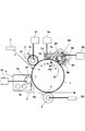
図1に、本発明を適用することができる画像形成装置を示す。同図に示す画像形成装置は、電子写真方式、接触帯電方式、反転現像方式のレーザビームプリンタであり、最大通紙サイズはA3サイズである。同図は、このプリンタを正面側、すなわちプリンタの操作時にユーザが位置する側から見た縦断面図に相当する模式図である。
<
FIG. 1 shows an image forming apparatus to which the present invention can be applied. The image forming apparatus shown in the figure is a laser beam printer of an electrophotographic system, a contact charging system, or a reversal developing system, and the maximum sheet passing size is A3 size. This figure is a schematic view corresponding to a longitudinal sectional view of the printer as viewed from the front side, that is, from the side where the user is located when operating the printer.
同図を参照して、プリンタ(以下「画像形成装置」という。)の構成及び動作の概略を説明する。 An outline of the configuration and operation of a printer (hereinafter referred to as “image forming apparatus”) will be described with reference to FIG.
(1)画像形成装置全体の概略構成
(a)像担持体(感光ドラム)
同図に示す画像形成装置は、像担持体として回転ドラム型の電子写真感光体(以下「感光ドラム」という。)1を備えている。この感光ドラム1は、感光層として負帯電特性の有機光半導体(OPC)を有している。感光ドラム1は、外径30mmであり、中心支軸を中心に150〜250mm/secのプロセススピード(周速度)をもって同図中の矢印R1方向(反時計回り)に回転駆動される。
(1) Schematic configuration of entire image forming apparatus (a) Image carrier (photosensitive drum)
The image forming apparatus shown in FIG. 1 includes a rotating drum type electrophotographic photosensitive member (hereinafter referred to as “photosensitive drum”) 1 as an image carrier. The
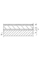
図2に感光ドラム1の層構成を模式的に示す。同図における上側及び下側は、実際の感光ドラム1のそれぞれ外側及び内側に対応している。この感光ドラム1は、アルミニウム等の導電性を有するドラム基体1aの表面に、光の干渉を抑え、上層の接着性を向上させる下引き層1bと、光電荷発生層1cと、電荷輸送層1dの3層を下側(内側)から順に塗り重ねた構成をしている。ドラム基体1aはアースされている。
FIG. 2 schematically shows the layer structure of the
(b)帯電手段(帯電ローラ)
感光ドラム1の周囲には、帯電手段としての帯電ローラ(接触帯電器)2が配設されている。帯電ローラ2は、感光ドラム1表面に接触するように配設されていて、感光ドラム1の表面(外周面)を一様に帯電処理するものである。
(B) Charging means (charging roller)
Around the
この帯電ローラ2は、芯金2aの外周面に弾性層2bを設けて構成されている。帯電ローラ2は、芯金2aの長手方向両端部がそれぞれ軸受部材(不図示)により回転自在に保持されている。また軸受部材は押圧ばね2cによって感光ドラム1表面に向けて付勢されている。これにより、帯電ローラ2は、感光ドラム1の表面に対して所定の押圧力をもって圧接させており、感光ドラム1の矢印R1方向の回転に伴って時計回り方向に従動回転する。感光ドラム1と帯電ローラ2との圧接部が帯電部(帯電ニップ部)aとなる。
The
帯電ローラ2の芯金2aには帯電バイアス印加電源S1から所定の条件の帯電バイアス電圧が印加される。例えば、直流電圧だけの場合や直流電圧に交流電圧を重畳させた場合などの条件である。回転中の感光ドラム1は、本実施の形態では、その表面(外周面)が負極性に一様に接触帯電処理される。
A charging bias voltage of a predetermined condition is applied to the cored
(c)情報書き込み手段(露光装置)
帯電後の感光ドラム1表面は、静電潜像形成手段としての露光装置3によって静電潜像が形成される。本実施の形態では、露光装置3は、半導体レーザ使用のレーザビームスキャナである。帯電器により帯電された感光体を画像情報に基づき露光する光学系の一例であるレーザビームスキャナは、画像読み取り装置(不図示)等のホスト装置から画像形成装置側に送られた画像信号に対応して変調されたレーザ光を出力して感光ドラム1の一様帯電処理面を露光位置bにおいてレーザ走査露光L(イメージ走査露光)する。このレーザ走査露光Lにより感光ドラム1面のレーザ光で照射されたところの電位が低下する。これにより、感光ドラム1表面に順次に静電潜像が形成される。これにより感光ドラム1面には走査露光した画像情報に対応した静電潜像が順次に形成されていく。
(C) Information writing means (exposure apparatus)
An electrostatic latent image is formed on the surface of the charged
(d)現像手段(現像装置)
感光ドラム1の回転方向に沿っての露光装置4の下流側には、現像装置4が配設されている。光学系により感光体に形成された静電潜像をトナーで現像する現像器の一例である現像装置4は、現像剤(トナー)を収納した現像容器4a、非磁性の現像スリーブ4b、マグネットローラ4c、規制ブレード4dを有している。
(D) Developing means (developing device)
Downstream of the exposing
現像スリーブ4bは、その外周面の一部を外部に露呈させて現像容器4a内に回転可能に配設されている。マグネットローラ4cは、固定状態(非回転)で現像スリーブ4b内に挿着されている。規制ブレード4dは、現像スリーブ4b上の現像剤の層厚を規制するものである。現像容器4aないには、現像剤として負の帯電特性を有する一成分磁性トナーが収納されている。現像スリーブ4bには、現像バイアス印加電源S2が接続されている。
The developing
上述構成の現像装置4においては、一成分磁性トナーが、時計回り方向に回転される現像スリーブ4b表面に規制ブレード4dによって薄層としてコーティングされる。このトナーは、現像スリーブ4bの回転に伴って、現像部cに搬送される。そして、現像バイアス印加電源S2によって現像スリーブ4bに印加された現像バイアスにより、感光ドラム1表面の静電潜像に対応して選択的に付着される。これにより感光ドラム1上の静電潜像がトナー像として現像される。本実施の形態では、ジャンピング現像により感光ドラム1表面の露光明部にトナーが付着されて、静電潜像が反転現像される。
In the developing
感光ドラム1表面に付着されないで、現像部cを通過した現像スリーブ4b上のトナーは、引き続く現像スリーブ4bの回転に伴い現像容器4a内の現像剤溜り部に戻される。
The toner on the developing
(e)転写手段(転写ローラ)
転写手段としては、感光ドラム1表面に接触配置された転写ローラ5が使用されている。感光ドラム1表面と転写ローラ5との間には、転写部dが形成されている。給搬送手段(不図示)によって転写部dに搬送されてきた転写材Pは、感光ドラム1と転写ローラ5とによって挟持搬送される。このとき、転写ローラ5に対し、転写バイアス印加電源S3から感光ドラム1上のトナーの正規帯電極性である負極性とは逆極性である正極性の転写バイアスが印加される。これにより、感光ドラム1上のトナー像が転写材Pに順次に静電転写されていく。
(E) Transfer means (transfer roller)
As the transfer means, a
(f)定着手段(定着装置)
トナー像転写後の転写材Pは、感光ドラム1表面から分離され、定着装置(不図示)に搬送される。転写材Pは、ここで加熱された定着ローラ(不図示)とこれに当接された加圧ローラ(不図示)によって挟持搬送される。このとき、転写材Pは加熱・加圧されて、表面にトナー像が定着される。トナー像定着後の転写材Pは、画像形成物(プリント、コピー)として画像形成装置本体(不図示)の外部に排出される。
(F) Fixing means (fixing device)
The transfer material P after the toner image is transferred is separated from the surface of the
本発明においては、感光ドラム1の回転方向に沿っての転写部dの下流側で、かつ帯電部aの上流側に、第1の画像履歴消去手段8とその下流側に第2の画像履歴消去手段7とを備えている。
In the present invention, the first image
(g)第1の画像履歴消去手段(第1補助帯電手段)
第1の回転履歴消去手段8は、感光ドラム1表面に接触した状態で矢印R8方向に回転する回転ブラシ8Aを有している。感光体に残留する転写残トナーとともに感光体を帯電すべくトナーの正規の帯電極性とは逆極性の電圧が印加される補助帯電ブラシの一例である回転ブラシ8Aの回転方向は、感光ドラム1表面に接触する部分が、感光ドラム1表面とは逆方向に移動する方向である。
(G) First image history erasing means (first auxiliary charging means)
The first rotation
回転ブラシ8Aは、感光ドラム1の中心軸(回転中心)よりも上方において、感光ドラム1表面と接触している。つまり、感光ドラム1表面と回転ブラシ8Aとの接触部eが、感光ドラム1の中心軸よりも高い位置に設定されている。これにより、回転ブラシ8Aの回転によって画像履歴を消去し、一部の現像剤を剥ぎ取った際に、現像剤の飛散、落下が発生しにくくなる。さらに、回転ブラシ8Aを囲むハウジング8a内に現像剤が堆積されにくくなる。
The rotating
また、回転ブラシ8Aの周速度をUb(mm/sec)、上述の感光ドラム1の周速度をUd(mm/sec)としたときに、Ub/Ud≦1の速度比になるように、回転ブラシ8Aを回転させている。転写材Pにトナー像を転写させた後の感光ドラム1表面は、接触部eにおいて回転ブラシ8Aによって摺擦される。これにより、トナー像転写時に転写材Pに転写されないで感光ドラム1表面に残っていたトナー(転写残トナー)は、回転ブラシ8Aによって補足されて、感光ドラム1表面から一時的に除去される。
Further, when the peripheral speed of the
また、回転ブラシ8Aの芯金8bには、バイアス印加電源(第1の電源)S5によって、帯電ローラ2による感光ドラム1の帯電極性とは逆極性のDC高圧に、AC高圧が重畳されて印加されている。すなわち、トナーの正規の帯電極性と逆極性の直流バイアスである。この「DC高圧+AC高圧」を印加することにより、転写部dの通過後に感光ドラム1表面に残存している潜像電位の履歴が、所定の電位へと収束される。本実施の形態においては、バイアス印加電源S5から回転ブラシ8Aに印加されるDC高圧は100〜400V程度である。重畳されるAC高圧としては、周波数が帯電ロ−ラ2のそれと同じ1000〜2000Hz、ピ−ク間電圧が200〜500V程度の矩形波が印加される。
Further, an AC high voltage is applied to the cored
また、感光ドラム1上の転写残トナ−は、転写できなかった低帯電、及び転写部分の剥離放電などにより、逆帯電したトナ−分布が混在している状態である。このため、積極的にDC高圧と、転写部d通過後のドラム電位(感光ドラム1の電位)との電位差によって移動ができない状態となっており、回転ブラシ8Aによる機械的な摩擦により剥ぎ取られるが、一部のトナ−は、そのまま接触部eを通過していくことになる。
Further, the transfer residual toner on the
接触部eにおいて、感光ドラム1表面から剥ぎ取られたトナーは、その後、図3に示す第一トナー移動部材及び第二トナー移動部材であるトナー分散化部材B1,B2に接触する。トナー分散化部材B1,B2は、補助帯電ブラシに接触するように設けられ補助帯電ブラシに付着した転写残トナーを補助帯電ブラシの回転に伴いその軸線方向に向けて移動させる。第一トナー移動部材であるトナー分散化部材B1は、図4に示すように、感光ドラム1表面の母線方向に沿って長く形成された板状のベース板9と、ベース板9における回転ブラシ8Aとの接触面9aに突設された角柱状の平行な複数のガイドb1(第一案内部)とを有している。平行な複数のガイドb1は、回転ブラシの回転方向(移動方向)に対して所定の角度θの角度の傾きをもって、ベース板9の長手方向に適宜な間隔で並べられている。角度θは、45°≦θ<90の範囲内に設定されている。すなわち補助帯電ブラシの母線方向と案内部との小さい方の角度は、0°より大きく45°以下である範囲である。また、相互に隣接するガイドb1,b1については、一部が感光ドラム1の母線方向にオーバーラップするように形成されている。つまり、感光ドラム1表面から回転ブラシ8Aによって剥ぎ取られたトナーが、必ずいずれかのガイドb1に衝突するようになっている。このようなトナー分散化部材B1に対して、第二トナー移動部材であるトナー分散化部材B2は、ガイドb1(第二案内部)の角度が−θとなる以外は同様な構成である。トナー分散化部材B1は、回転ブラシ8Aの回転方向に沿っての、接触部eの下流側に配設され、またトナー分散化部材B2は、トナー分散化部材B1の下流側に配設されている。なお、以上の説明では、トナー分散化部材B1,B2のそれぞれのガイドb1の回転ブラシ8Aの母線に対する傾きの角度が逆方向で、かつ絶対値が同じ場合を例に説明したが、絶対値は必ずしも一致しなくてもよい。
At the contact portion e, the toner peeled off from the surface of the
感光ドラム1表面のトナーは、接触部eにおいて、回転ブラシ8Aによる機械的な摩擦により、ブラシの回転方向に分散された状態で補足される。こうして回転ブラシ8Aに補足されたトナーは、トナー移動部材としてのトナー分散化部材B1,B2のガイドb1に沿って搬送される。これにより、トナーは、図3に示すように、トナー分散化部材B1、B2のガイドb1の角度±θと、ガイドb1の長さLで決まる移動距離±L´(=L×sin±θ)だけ、感光ドラム1表面の母線方向に移動することになる。
The toner on the surface of the
感光ドラム1表面から回転ブラシ8Aによって剥ぎ取られたトナ−の大部分は、このトナー分散化部材B1,B2に接触することにより、角度±θ方向、つまり感光ドラム1の回転方向及び母線方向に分散化されて画像履歴が消去される。分散化されたトナーは、その後、再度、回転ブラシ8Aに付着し、再度、感光ドラム1と接触することにより、再度、感光ドラム1表面に移動する。
Most of the toner peeled off from the surface of the
本実施の形態では、トナー分散化部材B1,B2の材質として、絶縁性の樹脂材質を採用している。これは、感光ドラム1から剥ぎ取ったトナ−の帯電極性に影響を与えることなく、画像履歴のみを消去することが目的だからである。
In the present embodiment, an insulating resin material is used as the material of the toner dispersion members B1 and B2. This is because only the image history is erased without affecting the charging polarity of the toner peeled off from the
上述のハウジング8aは、図1に示すように、断面が「コ字形」に形成されていて、回転ブラシ8A、トナー分散化部材B1,B2をほぼ3方から覆っている。また、ハウジング8aの上流側及び下流側の端部には、感光ドラム1表面との隙間を塞ぐために、トナー飛散防止シート8cが取り付けられている。これにより、回転ブラシ8Aによって剥ぎ取ったトナーが、ハウジング8a外部に漏れ出ることを防止している。
As shown in FIG. 1, the above-described
(h)第2の画像履歴消去手段(第2補助帯電手段)
上述のようにして、回転ブラシ8Aから再度、感光ドラム1表面に戻されたトナーは、感光ドラム1の矢印R1方向に回転に伴って、第2の画像履歴消去手段7に搬送される。第2の画像履歴消去手段7は、非回転ブラシ7Aを有している。非回転ブラシ7Aは、感光ドラム1回転方向に沿っての回転ブラシ8Aの下流側に、感光ドラム1bの母線方向に沿って長く配設されている。非回転ブラシ7Aは、その背面側及び下流側が、上述のハウジング8aと一体のハウジング7aによって覆われている。この非回転ブラシ7Aは、レシプロ機構(不図示)によって母線に沿って往復運動するようになっている。回転ブラシ8Aから再度、感光ドラム1表面に付着されたトナーは、この往復運動により、さらに母線方向に均一化される。
(H) Second image history erasing means (second auxiliary charging means)
As described above, the toner returned to the surface of the
非回転ブラシ7Aには、バイアス印加電源(第2の電源)S4から帯電ローラ2と同様の極性のDC高圧が印加されており、上述の回転ブラシ8Aの「AC+DC高圧」で履歴消去される。さらに、均一化された電位との間で、DC放電が発生する電位差になる条件で印加される。本実施の形態では、非回転ブラシ7Aに印加されるDC高圧値は、700〜900Vの範囲に設定される。
A DC high voltage having the same polarity as that of the charging
このDC放電により形成された帯電電位は、図5に示すように、帯電ローラ2に印加されるDC電圧よりも小さい電位条件になるように設定されている。これは、帯電ローラ2のDC電位を超えるドラム電位を、非回転ブラシ7Aで付与してしまうと、帯電電位むらが発生することになるので、これを防止するためである。なお、同図中のVL電位は明部電位を、またVD電位は暗部電位を示している。なお、本実施の形態では、非回転ブラシであったが、回転ブラシであっても問題ない。
As shown in FIG. 5, the charging potential formed by the DC discharge is set to have a potential condition smaller than the DC voltage applied to the charging
また、感光ドラム1上のトナーは、非回転ブラシ7Aと感光ドラム1との間のDC放電によって帯電ローラ2のDC高圧と同極性に帯電される。このとき、トナーの帯電状態は、現像装置4の中にある現像剤の帯電量と同等レベルまで帯電される。これにより、帯電ローラ2で形成した電位と、現像装置4のDC高圧とで形成される非画像部電位差によって行われる、いわゆる現像同時クリ−ニングが達成される。
The toner on the
以上説明したような、少なくとも第1の画像履歴消去手段及び第1履歴消去手段を用いることで、主走査方向のトナー濃度の比率に偏りがある画像を多く出力しても、補助帯電手段の長手方向における転写残トナーの分布の偏りを小さくすることができる。これにより、安定して画像履歴を消去することができる。そして、感光体に形成された静電潜像を現像器により現像するとき、補助帯電ブラシにより帯電された転写残トナーを現像器へ回収可能である。 By using at least the first image history erasing unit and the first history erasing unit as described above, the length of the auxiliary charging unit can be increased even if a large number of images having a biased toner density ratio in the main scanning direction are output. The deviation in the distribution of the transfer residual toner in the direction can be reduced. Thereby, the image history can be erased stably. When the electrostatic latent image formed on the photosensitive member is developed by the developing device, the transfer residual toner charged by the auxiliary charging brush can be collected in the developing device.
<実施の形態2>
上述の実施の形態1では、第1の画像履歴消去手段8のトナー分散化部材B1,B2は、感光ドラム1母線方向には不動であった。本実施の形態では、これら第1及び第2のトナー分散化部材B1,B2を感光ドラム1母線方向に往復移動可能に構成し、これをレシプロ機構(不図示)によって移動させることで、母線方向のトナーの分散能力をさらに高めるようにした。
<
In the first embodiment described above, the toner dispersion members B1 and B2 of the first image
レシプロ機構は、例えば、上述の非回転ブラシ7Aを移動させるためのレシプロ機構を兼用することができ、この場合には、個別に設ける場合に比べて構成を簡略化することができる。
For example, the reciprocating mechanism can also be used as a reciprocating mechanism for moving the
このように、第1及び第2のトナー分散化部材B1,B2を母線方向に往復移動させることにより、母線方向へのトナーの分散性を一層高めることができる。さらには、感光ドラム1へ再付着したトナーを、非回転ブラシ7Aを用いてさらに均一化しながら、トナーへの電荷注入の均一化と、帯電ローラ2へ供給する前帯電電位の安定化を図っている。
As described above, by reciprocating the first and second toner dispersing members B1 and B2 in the bus line direction, the dispersibility of the toner in the bus line direction can be further improved. Further, the toner adhering to the
本実施の形態の構成を用いることにより、現像同時クリーニングシステムにおいて、画像比率が大きい写真画像のような画像を、高速機で連続出力しても、転写残トナーの画像履歴によるゴースト画像や、帯電ローラ2に対する局所的な汚れを発生させることなく、安定した画像形成を達成することができる。
By using the configuration of the present embodiment, even in the simultaneous development cleaning system, even if an image such as a photographic image having a large image ratio is continuously output by a high-speed machine, a ghost image or charging due to the image history of the residual toner after transfer Stable image formation can be achieved without causing local contamination on the
1 感光ドラム(感光体)
2 帯電ローラ(帯電器)
3 露光装置(光学系)
4 現像装置(現像器)
7 第2の画像履歴消去手段
7A 非回転ブラシ(第2のブラシ部材)
8 第1の画像履歴消去手段
8A 回転ブラシ(補助帯電ブラシ)
B1 第1トナー分散化部材(第一トナー移動部材)
B2 第2トナー分散化部材(第二トナー移動部材)
b1 ガイド(第一案内部、第二案内部)
S4 バイアス印加電源(第2の電源)
S5 バイアス印加電源(第1の電源)
1 Photosensitive drum ( photoconductor )
2 Charging roller ( charger )
3 Exposure equipment ( optical system )
4 Development device ( developer )
7 Second image history erasing means 7A Non-rotating brush (second brush member)
8 First image
B1 First toner dispersing member ( first toner moving member)
B2 Second toner dispersing member ( second toner moving member)
b1 Guide ( first guide, second guide )
S4 Bias application power supply (second power supply)
S5 Bias application power supply (first power supply)
Claims (3)
前記補助帯電ブラシに接触するように設けられ、前記補助帯電ブラシの母線方向に対して所定の角度で傾けた平行な複数の第一案内部を有し、前記複数の第一案内部が前記補助帯電ブラシに接触して、前記補助帯電ブラシに付着した転写残トナーを前記補助帯電ブラシの回転に伴いその軸線方向に向けて移動させる第一トナー移動部材と、
前記第一トナー移動部材が前記補助帯電ブラシに接触する面とは異なる面で前記補助帯電ブラシに接触するように設けられ、前記補助帯電ブラシの母線方向に対する傾きの角度が前記複数の第一案内部とは異なる平行な複数の第二案内部を有し、前記複数の第二案内部が前記補助帯電ブラシに接触して、前記補助帯電ブラシに付着した転写残トナーを前記補助帯電ブラシの回転に伴い、その軸線方向に関して、前記第一トナー移動部材による移動方向と逆方向に向けて移動させる第二トナー移動部材と、
を有することを特徴とする画像形成装置。 A photoconductor, a charger for charging the photoconductor, an optical system for exposing the photoconductor charged by the charger based on image information, and an electrostatic latent image formed on the photoconductor by the optical system A developing unit that develops the toner with toner, a transfer charger that transfers the toner image formed on the photosensitive member by the developing unit to a transfer material, and the transfer residual toner remaining on the photosensitive member together with a predetermined potential. An auxiliary charging brush to which a voltage having a polarity opposite to the normal charging polarity of the toner is applied so that the electrostatic latent image formed on the photosensitive member is developed by the developing device. In the image forming apparatus capable of collecting the transfer residual toner charged by the charging brush into the developing unit,
A plurality of parallel first guide portions that are provided in contact with the auxiliary charging brush and are inclined at a predetermined angle with respect to a generatrix direction of the auxiliary charging brush, wherein the plurality of first guide portions are the auxiliary charging brushes; A first toner moving member that contacts the charging brush and moves the transfer residual toner attached to the auxiliary charging brush in the axial direction along with the rotation of the auxiliary charging brush ;
The first toner moving member is provided so as to contact the auxiliary charging brush on a surface different from a surface that contacts the auxiliary charging brush, and an inclination angle of the auxiliary charging brush with respect to a generatrix direction is the plurality of first guides. A plurality of second guide portions parallel to each other, the plurality of second guide portions contact the auxiliary charging brush, and transfer residual toner adhering to the auxiliary charging brush is rotated by the auxiliary charging brush. Accordingly, a second toner moving member that moves in a direction opposite to the moving direction by the first toner moving member with respect to the axial direction thereof;
An image forming apparatus, comprising a.
Priority Applications (2)
| Application Number | Priority Date | Filing Date | Title |
|---|---|---|---|
| JP2005347218A JP4804129B2 (en) | 2005-11-30 | 2005-11-30 | Image forming apparatus |
| US11/563,347 US7469116B2 (en) | 2005-11-30 | 2006-11-27 | Image forming apparatus |
Applications Claiming Priority (1)
| Application Number | Priority Date | Filing Date | Title |
|---|---|---|---|
| JP2005347218A JP4804129B2 (en) | 2005-11-30 | 2005-11-30 | Image forming apparatus |
Publications (3)
| Publication Number | Publication Date |
|---|---|
| JP2007155845A JP2007155845A (en) | 2007-06-21 |
| JP2007155845A5 JP2007155845A5 (en) | 2009-01-22 |
| JP4804129B2 true JP4804129B2 (en) | 2011-11-02 |
Family
ID=38121519
Family Applications (1)
| Application Number | Title | Priority Date | Filing Date |
|---|---|---|---|
| JP2005347218A Expired - Fee Related JP4804129B2 (en) | 2005-11-30 | 2005-11-30 | Image forming apparatus |
Country Status (2)
| Country | Link |
|---|---|
| US (1) | US7469116B2 (en) |
| JP (1) | JP4804129B2 (en) |
Families Citing this family (9)
| Publication number | Priority date | Publication date | Assignee | Title |
|---|---|---|---|---|
| JP2008129066A (en) * | 2006-11-16 | 2008-06-05 | Canon Inc | Image forming apparatus |
| JP4914707B2 (en) * | 2006-12-15 | 2012-04-11 | 株式会社リコー | Image forming apparatus |
| US7684732B2 (en) * | 2006-12-22 | 2010-03-23 | Ricoh Company, Ltd. | Process unit and image forming apparatus including the same |
| JP5279436B2 (en) * | 2008-10-09 | 2013-09-04 | キヤノン株式会社 | Image forming apparatus |
| JP4930496B2 (en) | 2008-12-08 | 2012-05-16 | コニカミノルタビジネステクノロジーズ株式会社 | Cleaning device and image forming apparatus having the same |
| JP5618760B2 (en) * | 2009-11-19 | 2014-11-05 | キヤノン株式会社 | Image forming apparatus |
| JP5839840B2 (en) * | 2011-05-26 | 2016-01-06 | キヤノン株式会社 | Image forming apparatus |
| JP7225361B1 (en) | 2021-12-17 | 2023-02-20 | キヤノン株式会社 | image forming device |
| US20230195025A1 (en) * | 2021-12-17 | 2023-06-22 | Canon Kabushiki Kaisha | Image forming apparatus |
Family Cites Families (9)
| Publication number | Priority date | Publication date | Assignee | Title |
|---|---|---|---|---|
| JPH0451073A (en) * | 1990-06-18 | 1992-02-19 | Toei Sangyo Kk | Electrophotographic device |
| JPH0553489A (en) | 1991-08-27 | 1993-03-05 | Ricoh Co Ltd | Cleaning device for image forming device |
| JPH05188842A (en) * | 1991-10-17 | 1993-07-30 | Fuji Xerox Co Ltd | Cleaning device |
| JPH0980998A (en) * | 1995-09-13 | 1997-03-28 | Tec Corp | Image forming device |
| JP3625360B2 (en) | 1997-08-04 | 2005-03-02 | キヤノン株式会社 | Image forming apparatus |
| US6219505B1 (en) * | 1998-09-30 | 2001-04-17 | Brother Kogyo Kabushiki Kaisha | Image forming apparatus having paper-dust removing devices |
| JP2004117960A (en) | 2002-09-27 | 2004-04-15 | Canon Inc | Image forming apparatus |
| JP2004126102A (en) | 2002-10-01 | 2004-04-22 | Canon Inc | Image forming apparatus |
| US20080107448A1 (en) * | 2006-11-03 | 2008-05-08 | Kabushiki Kaisha Toshiba | Image forming apparatus and image forming method |
-
2005
- 2005-11-30 JP JP2005347218A patent/JP4804129B2/en not_active Expired - Fee Related
-
2006
- 2006-11-27 US US11/563,347 patent/US7469116B2/en not_active Expired - Fee Related
Also Published As
| Publication number | Publication date |
|---|---|
| US7469116B2 (en) | 2008-12-23 |
| JP2007155845A (en) | 2007-06-21 |
| US20070122190A1 (en) | 2007-05-31 |
Similar Documents
| Publication | Publication Date | Title |
|---|---|---|
| JP4804129B2 (en) | Image forming apparatus | |
| JP2004117960A (en) | Image forming apparatus | |
| JP3647345B2 (en) | Image forming apparatus | |
| US7756446B2 (en) | Image forming apparatus | |
| JP2004354695A (en) | Image forming apparatus | |
| US7805089B2 (en) | Image forming apparatus | |
| US6611668B2 (en) | Image forming apparatus with residual developing charging feature | |
| JP2008070811A (en) | Charging device and image forming apparatus | |
| JP4307207B2 (en) | Image forming apparatus | |
| JP3768931B2 (en) | Image forming apparatus | |
| EP1467261A1 (en) | Image forming apparatus for preventing image deterioration caused by fallen conductive brush and scatter of developer | |
| JP2008009149A (en) | Image forming apparatus | |
| JP2007065591A (en) | Image forming apparatus | |
| US6944416B2 (en) | Image forming apparatus | |
| JP2008009148A (en) | Image forming apparatus | |
| JP4871578B2 (en) | Image forming apparatus | |
| JP2004126246A (en) | Image forming apparatus | |
| JP2003167476A (en) | Toner processing device, process cartridge and image forming apparatus | |
| JP2004054142A (en) | Image forming apparatus | |
| JPH11311916A (en) | Image forming device | |
| JP5609598B2 (en) | Lubricant supply device, image forming device | |
| JP2005070311A (en) | Image forming apparatus | |
| JP2009122445A (en) | Image forming apparatus | |
| JP2002014522A (en) | Image recorder | |
| JP2002031998A (en) | Image forming device |
Legal Events
| Date | Code | Title | Description |
|---|---|---|---|
| A521 | Request for written amendment filed |
Free format text: JAPANESE INTERMEDIATE CODE: A523 Effective date: 20081128 |
|
| A621 | Written request for application examination |
Free format text: JAPANESE INTERMEDIATE CODE: A621 Effective date: 20081128 |
|
| A977 | Report on retrieval |
Free format text: JAPANESE INTERMEDIATE CODE: A971007 Effective date: 20110127 |
|
| A131 | Notification of reasons for refusal |
Free format text: JAPANESE INTERMEDIATE CODE: A131 Effective date: 20110208 |
|
| A521 | Request for written amendment filed |
Free format text: JAPANESE INTERMEDIATE CODE: A523 Effective date: 20110407 |
|
| TRDD | Decision of grant or rejection written | ||
| A01 | Written decision to grant a patent or to grant a registration (utility model) |
Free format text: JAPANESE INTERMEDIATE CODE: A01 Effective date: 20110802 |
|
| A01 | Written decision to grant a patent or to grant a registration (utility model) |
Free format text: JAPANESE INTERMEDIATE CODE: A01 |
|
| A61 | First payment of annual fees (during grant procedure) |
Free format text: JAPANESE INTERMEDIATE CODE: A61 Effective date: 20110809 |
|
| FPAY | Renewal fee payment (event date is renewal date of database) |
Free format text: PAYMENT UNTIL: 20140819 Year of fee payment: 3 |
|
| LAPS | Cancellation because of no payment of annual fees |