US7463331B2 - Exposure apparatus and method for manufacturing device - Google Patents
Exposure apparatus and method for manufacturing device Download PDFInfo
- Publication number
- US7463331B2 US7463331B2 US11/859,541 US85954107A US7463331B2 US 7463331 B2 US7463331 B2 US 7463331B2 US 85954107 A US85954107 A US 85954107A US 7463331 B2 US7463331 B2 US 7463331B2
- Authority
- US
- United States
- Prior art keywords
- gas
- space
- optical elements
- exposure apparatus
- sections
- Prior art date
- Legal status (The legal status is an assumption and is not a legal conclusion. Google has not performed a legal analysis and makes no representation as to the accuracy of the status listed.)
- Expired - Fee Related
Links
Images


Classifications
-
- G—PHYSICS
- G03—PHOTOGRAPHY; CINEMATOGRAPHY; ANALOGOUS TECHNIQUES USING WAVES OTHER THAN OPTICAL WAVES; ELECTROGRAPHY; HOLOGRAPHY
- G03B—APPARATUS OR ARRANGEMENTS FOR TAKING PHOTOGRAPHS OR FOR PROJECTING OR VIEWING THEM; APPARATUS OR ARRANGEMENTS EMPLOYING ANALOGOUS TECHNIQUES USING WAVES OTHER THAN OPTICAL WAVES; ACCESSORIES THEREFOR
- G03B27/00—Photographic printing apparatus
- G03B27/32—Projection printing apparatus, e.g. enlarger, copying camera
- G03B27/52—Details
-
- G—PHYSICS
- G03—PHOTOGRAPHY; CINEMATOGRAPHY; ANALOGOUS TECHNIQUES USING WAVES OTHER THAN OPTICAL WAVES; ELECTROGRAPHY; HOLOGRAPHY
- G03F—PHOTOMECHANICAL PRODUCTION OF TEXTURED OR PATTERNED SURFACES, e.g. FOR PRINTING, FOR PROCESSING OF SEMICONDUCTOR DEVICES; MATERIALS THEREFOR; ORIGINALS THEREFOR; APPARATUS SPECIALLY ADAPTED THEREFOR
- G03F7/00—Photomechanical, e.g. photolithographic, production of textured or patterned surfaces, e.g. printing surfaces; Materials therefor, e.g. comprising photoresists; Apparatus specially adapted therefor
- G03F7/70—Microphotolithographic exposure; Apparatus therefor
- G03F7/708—Construction of apparatus, e.g. environment aspects, hygiene aspects or materials
- G03F7/70908—Hygiene, e.g. preventing apparatus pollution, mitigating effect of pollution or removing pollutants from apparatus
- G03F7/70933—Purge, e.g. exchanging fluid or gas to remove pollutants
-
- G—PHYSICS
- G03—PHOTOGRAPHY; CINEMATOGRAPHY; ANALOGOUS TECHNIQUES USING WAVES OTHER THAN OPTICAL WAVES; ELECTROGRAPHY; HOLOGRAPHY
- G03F—PHOTOMECHANICAL PRODUCTION OF TEXTURED OR PATTERNED SURFACES, e.g. FOR PRINTING, FOR PROCESSING OF SEMICONDUCTOR DEVICES; MATERIALS THEREFOR; ORIGINALS THEREFOR; APPARATUS SPECIALLY ADAPTED THEREFOR
- G03F7/00—Photomechanical, e.g. photolithographic, production of textured or patterned surfaces, e.g. printing surfaces; Materials therefor, e.g. comprising photoresists; Apparatus specially adapted therefor
- G03F7/70—Microphotolithographic exposure; Apparatus therefor
- G03F7/708—Construction of apparatus, e.g. environment aspects, hygiene aspects or materials
- G03F7/70991—Connection with other apparatus, e.g. multiple exposure stations, particular arrangement of exposure apparatus and pre-exposure and/or post-exposure apparatus; Shared apparatus, e.g. having shared radiation source, shared mask or workpiece stage, shared base-plate; Utilities, e.g. cable, pipe or wireless arrangements for data, power, fluids or vacuum
Definitions
- the present invention relates to an exposure apparatus and a method for manufacturing a device.
- Conventional exposure apparatuses for manufacturing semiconductor integrated circuits use light of various wavelengths for exposure.
- the followings are used for exposure: an i-line with a wavelength of 365 nm, a KrF excimer laser beam with a wavelength of 248 nm, an ArF excimer laser beam with a wavelength of 193 nm, and X-rays.
- Light emitted from a light source passes through a projection optical system, including projection lenses, for projecting a pattern formed on an original onto a substrate. This forms the pattern on the substrate.
- the conventional exposure apparatuses need to have high throughput and high resolution because of the reduction in the width of pattern lines. Therefore, high-energy exposure sources are being demanded and light with a shorter wavelength is also being demanded for exposure.
- Exposure light with a short wavelength is known to cause the photochemical reaction between oxygen and impurities present in the exposure apparatuses.
- the products of the photochemical reaction that is, chemical contaminants adhere to optical elements, such as lenses and mirrors, included in optical systems disposed in the exposure apparatuses. This causes a problem that fog is caused in the exposure light.
- the impurities include basic gases derived from resists and organic silicon compounds, such as siloxanes, derived from adhesives used for the optical elements.
- the impurities cover gaseous substances and solid substances, for example, suspended particulate matter.
- An exposure apparatus is usually placed in a chamber.
- the chamber includes a gas temperature control unit, an ultra-low penetration air (ULPA) filter, and a chemical filter. Gas supplied to the chamber is maintained at a constant temperature and has an extremely low impurity content.
- ULPA ultra-low penetration air
- an adhesive is used to fix optical elements to supporting members disposed in a lens barrel.
- the adhesive is usually an elastic adhesive, which usually contains a siloxane.
- the siloxane can cause fog in these optical elements. Therefore, the concentration of impurities in the lens barrel needs to be low.
- Japanese Patent Laid-Open No. 11-145053 proposes a lens barrel 220 shown in FIG. 20 .
- the lens barrel 220 includes lenses 230 and supporting members 231 , having openings 232 , for supporting the lenses 230 .
- This configuration allows gas to flow through spaces partitioned by the lenses 230 and the supporting members 231 .
- the lens barrel 220 is connected to a supply unit 206 and a recovery unit 207 ; hence, the atmosphere in the lens barrel 220 can be replaced with a purge gas.
- Japanese Patent Laid-Open No. 2005-183624 proposes lens barrels 123 shown in FIG. 21 .
- the lens barrels 123 include gas guides 125 for guiding a purge gas G to lenses 118 having a gap L 1 therebetween. This configuration is effective in efficiently removing impurities from the lens barrels 123 .
- the lens barrel 220 disclosed in Japanese Patent Laid-Open No. 11-145053 although the openings 232 are arranged around each lens 230 as shown in FIG. 20 , the purge gas hardly flows on the lens 230 . Therefore, if impurities causing fog are produced in the lens barrel 220 , the concentration of the impurities present on the lens 230 is high because of diffusion and cannot be sufficiently reduced.
- the purge gas G flows on the lenses 118 as shown in FIG. 21 . An increase in the amount of the purge gas G flowing on each lens 118 causes an increase in the amount of chemical contaminants. Therefore, the lens barrels 123 disclosed in Japanese Patent Laid-Open No. 2005-183624 are ineffective in preventing the fog of the lens 118 .
- Lenses usually have an axisymmetric spherical surface or axisymmetric aspherical surface. Therefore, although the temperature distribution in the lenses or the distortion thereof may deteriorate optical properties of optical systems, the optical aberration caused by the temperature distribution or the distortion can be readily corrected when the temperature distribution or the distortion is axisymmetric.
- the lens barrels 123 disclosed in Japanese Patent Laid-Open No. 2005-183624 if the purge gas G flows on each lens 118 in one direction, the temperature distribution in the lens 118 is not axisymmetric; hence, it is difficult to correct the optical aberration caused by the temperature distribution.
- the present invention provides an exposure apparatus in which properties of optical elements can be prevented from being deteriorated.
- An aspect of the present invention provides an exposure apparatus used to expose a substrate.
- This exposure apparatus includes an optical system which includes two optical elements and which is configured to guide light emitted from a light source to the substrate, gas supply sections configured to supply gas to a space between the optical elements, and gas exhaust sections configured to exhaust the gas from the space. The gas is supplied to the space such that a swirl flow is formed in the space.
- FIG. 1 is a schematic view of an example exposure apparatus according to an embodiment of the present invention.
- FIG. 2 is a schematic view of an example lens barrel.
- FIG. 3 is an enlarged view of a lens barrel unit included in the exposure apparatus shown in FIG. 1 .
- FIG. 4 is a sectional view of the lens barrel unit 13 taken along the line VI-VI of FIG. 3 .
- FIG. 5 is a horizontal sectional view of the lens barrel unit taken along a plane including gas supply pipes shown in FIG. 3 .
- FIG. 6 is a horizontal sectional view of the lens barrel unit taken along a plane including gas exhaust pipes shown in FIG. 3 .
- FIG. 7A is an illustration of a support member having grooves with a rectangular shape in cross section
- FIG. 7B is an illustration of a support member having grooves with a tapered shape in cross section
- FIG. 7C is an illustration of a support member having grooves with a trapezoidal shape in cross section.
- FIG. 8 is an illustration of a support member having ridges.
- FIG. 9 is a top view of the support member shown in FIG. 7A .
- FIG. 10 is an illustration showing nozzles.
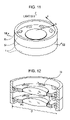
- FIG. 11 is an enlarged view of a lens barrel unit 14 shown in FIG. 1 .
- FIG. 12 is a sectional view of the lens barrel unit taken along the line XII-XII of FIG. 11 .
- FIG. 13 is a top view of a support member disposed in the lens barrel unit shown in FIG. 12 .
- FIG. 14 is a sectional view of the support member taken along the line XIV-XIV of FIG. 13 .
- FIG. 15 is an illustration showing impurity-adsorbing members.
- FIG. 16 is a perspective view of a support member.
- FIG. 17 is an illustration showing nozzles.
- FIG. 18 is a flow chart illustrating an example method for manufacturing a device.
- FIG. 19 is a flow chart illustrating Step S 4 shown in FIG. 18 .
- FIG. 20 is a sectional view of a lens barrel disclosed in Japanese Patent Laid-Open No. 11-145053.
- FIG. 21 is an illustration showing conventional lens barrels.
- FIG. 1 schematically shows an exposure apparatus according to an embodiment of the present invention.
- the exposure apparatus is usually placed in a chamber, which is not shown.
- the chamber includes a gas temperature control unit, a ULPA filter, and a chemical filter.
- the atmosphere in the chamber is maintained at a constant temperature and has an extremely low impurity content.
- the exposure apparatus includes an illumination optical system 7 , an original stage 6 for supporting an original 5 , a lens barrel 1 for projection, a substrate stage 4 for supporting a substrate 3 , a body base 2 , and a support frame 8 .
- the substrate stage 4 , the lens barrel 1 , and the support frame 8 are disposed on the body base 2 .
- the original stage 6 is disposed on the support frame 8 .
- the illumination optical system 7 illuminates the original 5 with light 12 emitted from a light source.
- the lens barrel 1 includes a projection optical system and projects a pattern onto the substrate 3 through the original 5 .
- the substrate 3 is a wafer or a glass plate and is coated with a photosensitizing agent.
- the original 5 is a reticle or a mask and has a circuit pattern for exposing the substrate 3 .
- pipes which are provided which extend through the wall of the lens barrel 1 which include gas supply pipes 9 , serving as gas supply sections, for introducing gas into the lens barrel 1 and gas exhaust pipes 10 , serving as gas exhaust sections, for discharging gas from the lens barrel 1 .
- a gas PG is introduced into the lens barrel 1 through the gas supply pipes 9 and then exhausted from the lens barrel 1 through the gas exhaust pipes 10 , whereby the atmosphere in the lens barrel 1 is replaced the gas PG.
- a gas supply unit is located upstream of the gas supply pipes 9 and controls the temperature and humidity of the gas PG and the content of impurities in the gas PG.
- the gas PG include rare gases such as helium, neon, argon, and krypton and inert gases such as nitrogen.
- a gas purification unit for purifying an outlet gas OG exhausted from the lens barrel 1 may be provided downstream of the gas exhaust pipes 10 such that the outlet gas OG is recycled.
- the gas PG may be supplied to a portion of the lens barrel 1 so as to fill the lens barrel 1 and then exhausted from another portion of the lens barrel 1 as shown in FIG. 1 or may be supplied to a specific portion of a lens barrel unit 13 as shown in FIG. 2 .
- FIG. 3 is an enlarged view of the lens barrel unit 13 .
- the lens barrel unit 13 is included in the lens barrel 1 .
- the light axis of the projection optical system is defined as the Z coordinate of a cylindrical coordinate system
- the radial direction of optical elements 11 disposed in the lens barrel unit 13 is defined as an R direction
- the circumferential direction of the optical elements 11 is defined as a ⁇ direction as shown in FIG. 3 .
- the optical elements 11 are each fixed in a support member 15 with an adhesive 16 .
- the support members 15 are each fitted in a lens tube 17 .
- optical elements 11 examples include lenses, mirrors, and diffractive optical elements.
- the optical elements 11 and the support members 15 can be distorted (e.g., expanded or contracted). Therefore, if each optical element 11 and support member 15 are rigidly fixed together, optical properties of the optical element 11 are deteriorated because the stress caused by the distortion of the optical element 11 and the support member 15 is applied to the optical element 11 .
- the adhesive 16 is preferably an elastic adhesive.
- Such an elastic adhesive contains a low-molecular weight organic compound such as a solvent, a modified silicone resin serving as a principal component, and an epoxy resin and therefore emits out gases, or impurities.
- the out gases have been the cause of chemical contamination.
- FIG. 4 is a sectional view of the lens barrel unit 13 taken along the line IV-IV of FIG. 3 .
- the lens barrel unit 13 has closed spaces 18 surrounded by the optical elements 11 , the support members 15 , and the lens tubes 17 .
- the size of the closed spaces 18 is substantially defined by the inside diameter D of the lens tubes 17 and the distance H between two of the support members 15 arranged in the Z direction.
- the height of a center portion of each closed space 18 may be less or greater than the distance H between two of the support members 15 depending on the surface curvature of the optical elements 11 . Since the adhesive 16 emits the impurities in the closed spaces 18 even if a sufficient amount of time has elapsed, molecules 19 of the impurities are present in the closed spaces 18 .
- FIG. 5 is a horizontal sectional view of the lens barrel unit 13 taken along a plane including the gas supply pipes 9 shown in FIG. 3 .
- reference numeral 23 denotes the intersection of the central axis 21 of each gas supply pipe 9 and the inner wall of each lens tube 17 .
- An axis 22 extends from the Z coordinate to the intersection 23 in the radial direction of the lens tube 17 .
- the central axis 21 and the axis 22 form an angle ⁇ .
- the gas PG supplied to each closed space 18 through the gas supply pipe 9 forms a swirl flow 20 centered at the Z coordinate.
- the swirl flow 20 has a flow velocity vector with a circumferential vector component.
- the impurity molecules 19 move around the Z coordinate at an angular velocity ⁇ together with the swirl flow 20 .
- the impurity molecules 19 spaced from the Z coordinate at a distance r receive a force f.
- FIG. 6 is a horizontal sectional view of the lens barrel unit 13 taken along a plane including the gas exhaust pipes 10 shown in FIG. 3 .
- reference numeral 26 denotes the intersection of the central axis 24 of each gas exhaust pipe 10 and the inner wall of each lens tube 17 .
- An axis 25 extends from the Z coordinate to the intersection 26 in the radial direction of the lens tube 17 .
- the central axis 24 and the axis 25 form an angle ⁇ .
- the gas PG supplied to the closed space 18 has a circumferential vector component and forms the swirl flow 20 .
- the angle ⁇ is preferably close to 90 degrees and more preferably greater than 45 degree and less than 90 degrees.
- the gas supply pipes 9 and the gas exhaust pipes 10 are preferably arranged rotationally symmetrically with respect to the Z coordinate.
- the force f is represented by the following formula: ( ⁇ ) ⁇ r ⁇ 2 (1) wherein ⁇ is the density of the impurities, ⁇ is the density of the gas PG, r is the distance between the Z coordinate and the impurity molecules 19 , and ⁇ is the angular velocity of the impurity molecules 19 .
- the term r ⁇ 2 represents the centrifugal acceleration.
- the impurity molecules 19 When ( ⁇ )>0, the impurity molecules 19 receive a positive force in the radial direction of the lens tube 17 . Therefore, the impurity molecules 19 move in the radial direction thereof. This increases the concentration of the impurities in a peripheral portion of the closed space 18 and therefore reduces the concentration of the impurities present on the optical element 11 .
- the impurities in the peripheral portion of the closed space 18 Since the concentration of the impurities in the peripheral portion of the closed space 18 is high, the impurities can be efficiently exhausted through the gas exhaust pipes 10 as shown in FIG. 6 .
- Substances causing the above fog are known to be gaseous siloxanes containing silicon, trimethylsilyl (TMS), and hexamethyldisilazane (HMDS) from the results of analysis.
- the impurities have a density of greater than 3 kg/m 3 at normal temperature and pressure. Therefore, the gas PG, which is supplied to the closed space 18 , is preferably helium, neon, argon, or nitrogen because helium has a density of 0.16 kg/m 3 , neon has a density of 0.82 kg/m 3 , argon has a density of 1.6 kg/m 3 , and nitrogen has a density of 1.1 kg/m 3 at normal temperature and pressure.
- Formula (1) shows that in order to efficiently reduce the concentration of the impurities present on the optical element 11 , the density ⁇ of the gas PG is preferably less than the density ⁇ of the impurities and the angular velocity ⁇ of the impurity molecules 19 is preferably large.
- the closed space 18 has an inner diameter D of about 240 mm, the distance H between the optical elements 11 is about 20 mm, the gas PG is nitrogen, the angles ⁇ and ⁇ are about 70 degrees, the gas supply pipes 9 and the gas exhaust pipes 10 have an inner cross-sectional area of about 100 mm 2 , the number of the gas supply pipes 9 is four, and the number of the gas exhaust pipes 10 is four.
- the gas PG When the gas PG is supplied to the closed space 18 through the gas supply pipes 9 at a velocity of about 5 m/s, the gas PG flows in the peripheral portion of the closed spaces 18 at a velocity of about 3.5 m/s in the circumferential direction of the closed space 18 .
- the flow rate of the gas PG is about 841 L/min.
- the angular velocity ⁇ of the impurity molecules 19 is about 35 rad/s. If the impurity molecules 19 are shifted in the radial direction of the closed space 18 , the angular velocity ⁇ thereof is hardly varied.
- the impurity molecules 19 present on the Z coordinate receive no centrifugal acceleration but the impurity molecules 19 apart from the Z coordinate receive a centrifugal acceleration. In usual, molecules of gas and suspended particulate matter are in thermal motion and therefore do not stay at fixed positions.
- the adhesive 16 which is the source of the impurities as described above, is spaced from the Z coordinate; hence, the impurities emitted in the closed space 18 immediately receive a centrifugal force. This reduces the concentration of the impurities on the optical elements 11 .
- the presence of the swirl flow 20 in the closed space 18 can create a pressure difference in the closed space 18 depending on the viscosity coefficient of the gas PG and/or the configuration of the gas exhaust pipes 10 such that the pressure in a peripheral portion is higher than that in a center portion of the closed space 18 . Since the velocity of the swirl flow 20 located very close to each support member 15 is close to zero, the impurities move on a surface of the support member 15 in the ⁇ R direction because of the pressure difference. This is referred to as secondary flow.
- support members 15 a shown in FIG. 7A may be used instead of the support members 15 .
- the support members 15 a have support portions for supporting the optical elements 11 and also have grooves 150 extending outward from the support portions.
- the grooves 150 may have a rectangular shape, a tapered shape, or a trapezoidal shape in cross section as shown in FIG. 7A , 7 B, or 7 C, respectively, when viewed in the longitudinal direction thereof.
- the grooves 150 may have another shape in cross section.
- support members 15 b shown in FIG. 8 may be used instead of the support members 15 .
- the support members 15 b have support portions for supporting the optical elements 11 and ridges 151 extending outward from the support portions.
- the ridges 151 as well as the grooves 150 may have a rectangular shape, a tapered shape, a trapezoidal shape, or another shape in cross section.
- FIG. 9 is a top view of one of the support members 15 a .
- the grooves 150 each have an axis 27 .
- Reference numeral 28 denotes the intersection of the axis 27 and the inner edge of each support member 15 a .
- An axis 29 extends from the Z coordinate toward the intersection 28 .
- the axes 27 and 29 form an angle ⁇ .
- the swirl flow 20 is applied to one of the walls of the grooves 150 , whereby a sub-flow parallel to the axis 27 is formed near a surface of the support member 15 a .
- the angle ⁇ is greater than 0 degree and less than 90 degrees, the sub-flow parallel to the axis 27 has a vector component directed in the +R direction. This prevents the secondary flow to move the impurities outward. This advantage can be achieved using the support members 15 b.
- the swirl flow 20 is formed in such a manner that the gas supply pipes 9 are communicatively connected to each lens tube 17 such that the angle ⁇ is greater than zero degree and less than 90 degrees. It may be difficult to communicatively connect the gas supply pipes 9 to the lens tube 17 such that the angle ⁇ is within the above range, depending on a material for forming the lens tube 17 .
- the gas supply pipes 9 may be communicatively connected to the lens tube 17 such that the central axes 30 of the gas supply pipes 9 extend in the radial direction of the lens tube 17 .
- nozzles 31 may be provided in the lens tube 17 such that openings of the nozzles 31 are connected to the gas supply pipes 9 as shown in FIG.
- the gas supply pipes 9 can be readily connected to the lens tube 17 .
- the gas PG is supplied to the closed space 18 through the nozzles 31 so as to have a circumferential vector component, whereby the swirl flow 20 is formed.
- the swirl flow 20 can be formed.
- FIG. 11 is a partially enlarged view of a lens barrel unit 14 shown in FIG. 1 .
- a cylindrical coordinate system is defined in the same manner as that described above with reference to FIG. 3 .
- the radial direction of optical elements is defined as an R direction, and the circumferential direction of the optical elements is defined as a ⁇ direction.
- This embodiment is different from the first embodiment in that support members 32 each have through-holes 33 .
- the through-holes 33 serve as gas supply sections for supplying gas to a closed space located thereon or serve as gas exhaust sections for discharging gas from a closed space located thereunder.
- FIG. 12 is a sectional view of the lens barrel unit 14 taken along the line XII-XII of FIG. 11 .
- FIG. 13 is a top view of one of the support members 32 .
- Reference numeral 35 represents the central axis of each through-hole 33 .
- FIG. 14 is a sectional view of the support member 32 taken along the line XIV-XIV of FIG. 13 .
- the central axis 35 of the through-hole 33 is tilted against the Z coordinate and the central axis 35 and the Z coordinate form an angle ⁇ .
- the angle ⁇ is greater than zero degree and less than 90 degrees, the gas PG supplied to each closed space 18 has a circumferential vector component and therefore a swirl flow can be formed.
- the angle ⁇ is preferably close to 90 degrees and more preferably greater than 45 degrees and less than 90 degrees.
- the closed space 18 has an inner diameter D of about 240 mm, the distance H between the optical elements is about 20 mm, the gas PG is nitrogen, the through-holes 33 have a cross-sectional area of about 71 mm 2 , the number of the through-holes 33 arranged in each support member 32 is eight, and the gas PG is supplied to the closed space 18 at a velocity of about 5 m/s.
- This allows the gas PG to flow in a peripheral portion of the closed space 18 at a velocity of about 3.7 m/s in the circumferential direction of the closed space 18 .
- the flow rate of the gas PG is about 130 L/min.
- the angular velocity ⁇ of molecules of impurities is about 37 rad/s. If the impurity molecules are shifted in the radial direction of the closed space 18 , the angular velocity ⁇ thereof is hardly varied.
- the closed spaces 18 are communicatively connected to each other with the through-holes 33 arranged in the support members 32 .
- the gas PG is supplied to one of the closed spaces 18 from the outside of a lens barrel 1 and is then exhausted from the lens barrel 1 through one of the closed spaces 18 that is located most downstream. Therefore, as the gas PG approaches the most downstream closed space 18 , the concentration of the impurities in the gas PG becomes high.
- impurity-adsorbing members 36 may be arranged on the inner surface of the lens barrel 1 as shown in FIG. 15 .
- the impurity-adsorbing members 36 may be arranged in one or more of the closed spaces 18 that are located downstream.
- the impurity-adsorbing members 36 may be made of a material, such as active carbon, a porous ceramic material, or a porous metal, capable of adsorbing gaseous siloxanes.
- the impurity-adsorbing members 36 When the impurity-adsorbing members 36 are arranged on portions on which the impurity concentration is high, the impurity concentration can be efficiently reduced. Although the closed spaces 18 are communicatively connected to each other, the concentration of the impurities on the optical elements 11 can be maintained low.
- the swirl flow is formed in such a manner that the through-holes 33 are arranged in each support member 32 such that the angle ⁇ is greater than zero degree and less than 90 degrees. It may be difficult to arrange the through-holes 33 in the support member 32 such that the angle ⁇ is as described above, depending on a material for forming the support member 32 .
- the through-holes 33 are arranged in the support member 32 such that the central axis 35 of each through-hole 33 is parallel to the Z coordinate as shown in FIG. 16 .
- nozzles 37 having openings directed in the circumferential direction of the support member 32 may be connected to the through-holes 33 as shown in FIG. 17 . According to this configuration, the through-holes 33 can be readily provided in the support member 32 and the nozzles 37 allow the gas PG, which is supplied to each closed space 18 , to have a circumferential vector component. This is effective in forming the swirl flow.
- FIG. 18 is a flow chart illustrating the method.
- the manufacture of semiconductor devices is described.
- Step S 1 circuits for the semiconductor devices are designed.
- Step S 2 a reticle having a pattern for forming the circuits is prepared.
- Step S 3 a wafer is produced from a semiconductor material such as silicon.
- Step S 4 which is referred to as a front end step, the circuits are formed on the wafer by lithography using the reticle.
- Step S 5 which is referred to as a back end step, the wafer treated in Step S 4 is processed into semiconductor chips.
- Step S 5 includes an assembly sub-step including a dicing operation and a bonding operation and a packaging sub-step including a chip-sealing operation.
- Step S 6 the semiconductor devices obtained in Step S 5 are inspected operation, durability, and the like. The semiconductor devices are completed through these steps.
- Step S 7 the semiconductor devices are delivered.
- FIG. 19 is a flow chart illustrating Step S 4 .
- the wafer is surface-oxidized.
- an insulating layer is formed on the wafer by chemical vapor deposition (CVD).
- electrodes are formed on the wafer by vapor deposition or the like.
- ions are implanted into the wafer.
- a resist and a photosensitizing agent are applied to the wafer.
- the wafer is exposed with the exposure apparatus such that the circuit pattern is transferred to the wafer.
- Sub-step S 17 the exposed wafer is developed.
- Sub-step S 18 portions other than an image formed by developing the resist are removed by etching.
- Sub-step S 19 the resist, which has been etched and is not necessary, is removed. Patterns that are the same as the circuit pattern are formed on the wafer by repeating these sub-steps.
- the method of this embodiment is effective in manufacturing higher-quality devices as compared to conventional methods.
Abstract
An exposure apparatus used to expose a substrate includes an optical system which includes two optical elements and which is configured to guide light emitted from a light source to the substrate, gas supply sections configured to supply gas to a space between the optical elements, and gas exhaust sections configured to exhaust the gas from the space. The gas is supplied to the space such that a swirl flow is formed in the space.
Description
1. Field of the Invention
The present invention relates to an exposure apparatus and a method for manufacturing a device.
2. Description of the Related Art
Conventional exposure apparatuses for manufacturing semiconductor integrated circuits use light of various wavelengths for exposure. The followings are used for exposure: an i-line with a wavelength of 365 nm, a KrF excimer laser beam with a wavelength of 248 nm, an ArF excimer laser beam with a wavelength of 193 nm, and X-rays. Light emitted from a light source passes through a projection optical system, including projection lenses, for projecting a pattern formed on an original onto a substrate. This forms the pattern on the substrate. The conventional exposure apparatuses need to have high throughput and high resolution because of the reduction in the width of pattern lines. Therefore, high-energy exposure sources are being demanded and light with a shorter wavelength is also being demanded for exposure.
Exposure light with a short wavelength is known to cause the photochemical reaction between oxygen and impurities present in the exposure apparatuses. The products of the photochemical reaction, that is, chemical contaminants adhere to optical elements, such as lenses and mirrors, included in optical systems disposed in the exposure apparatuses. This causes a problem that fog is caused in the exposure light. Examples of the impurities include basic gases derived from resists and organic silicon compounds, such as siloxanes, derived from adhesives used for the optical elements. The impurities cover gaseous substances and solid substances, for example, suspended particulate matter.
An exposure apparatus is usually placed in a chamber. The chamber includes a gas temperature control unit, an ultra-low penetration air (ULPA) filter, and a chemical filter. Gas supplied to the chamber is maintained at a constant temperature and has an extremely low impurity content.
There are many impurity sources in the exposure apparatus. For example, an adhesive is used to fix optical elements to supporting members disposed in a lens barrel. The adhesive is usually an elastic adhesive, which usually contains a siloxane. The siloxane can cause fog in these optical elements. Therefore, the concentration of impurities in the lens barrel needs to be low.
In order to solve the problem, Japanese Patent Laid-Open No. 11-145053 proposes a lens barrel 220 shown in FIG. 20 . The lens barrel 220 includes lenses 230 and supporting members 231, having openings 232, for supporting the lenses 230. This configuration allows gas to flow through spaces partitioned by the lenses 230 and the supporting members 231. The lens barrel 220 is connected to a supply unit 206 and a recovery unit 207; hence, the atmosphere in the lens barrel 220 can be replaced with a purge gas.
Japanese Patent Laid-Open No. 2005-183624 proposes lens barrels 123 shown in FIG. 21 . The lens barrels 123 include gas guides 125 for guiding a purge gas G to lenses 118 having a gap L1 therebetween. This configuration is effective in efficiently removing impurities from the lens barrels 123.
In the lens barrel 220 disclosed in Japanese Patent Laid-Open No. 11-145053, although the openings 232 are arranged around each lens 230 as shown in FIG. 20 , the purge gas hardly flows on the lens 230. Therefore, if impurities causing fog are produced in the lens barrel 220, the concentration of the impurities present on the lens 230 is high because of diffusion and cannot be sufficiently reduced. In the lens barrels 123 disclosed in Japanese Patent Laid-Open No. 2005-183624, the purge gas G flows on the lenses 118 as shown in FIG. 21 . An increase in the amount of the purge gas G flowing on each lens 118 causes an increase in the amount of chemical contaminants. Therefore, the lens barrels 123 disclosed in Japanese Patent Laid-Open No. 2005-183624 are ineffective in preventing the fog of the lens 118.
Lenses usually have an axisymmetric spherical surface or axisymmetric aspherical surface. Therefore, although the temperature distribution in the lenses or the distortion thereof may deteriorate optical properties of optical systems, the optical aberration caused by the temperature distribution or the distortion can be readily corrected when the temperature distribution or the distortion is axisymmetric. However, in the lens barrels 123 disclosed in Japanese Patent Laid-Open No. 2005-183624, if the purge gas G flows on each lens 118 in one direction, the temperature distribution in the lens 118 is not axisymmetric; hence, it is difficult to correct the optical aberration caused by the temperature distribution.
The present invention provides an exposure apparatus in which properties of optical elements can be prevented from being deteriorated.
An aspect of the present invention provides an exposure apparatus used to expose a substrate. This exposure apparatus includes an optical system which includes two optical elements and which is configured to guide light emitted from a light source to the substrate, gas supply sections configured to supply gas to a space between the optical elements, and gas exhaust sections configured to exhaust the gas from the space. The gas is supplied to the space such that a swirl flow is formed in the space.
Further features and aspects of the present invention will become apparent from the following description of exemplary embodiments with reference to the attached drawings.
Various embodiments of the present invention will now be described with reference to the attached drawings. FIG. 1 schematically shows an exposure apparatus according to an embodiment of the present invention.
The exposure apparatus is usually placed in a chamber, which is not shown. The chamber includes a gas temperature control unit, a ULPA filter, and a chemical filter. The atmosphere in the chamber is maintained at a constant temperature and has an extremely low impurity content.
With reference to FIG. 1 , the exposure apparatus includes an illumination optical system 7, an original stage 6 for supporting an original 5, a lens barrel 1 for projection, a substrate stage 4 for supporting a substrate 3, a body base 2, and a support frame 8. The substrate stage 4, the lens barrel 1, and the support frame 8 are disposed on the body base 2. The original stage 6 is disposed on the support frame 8.
The illumination optical system 7 illuminates the original 5 with light 12 emitted from a light source. The lens barrel 1 includes a projection optical system and projects a pattern onto the substrate 3 through the original 5. The substrate 3 is a wafer or a glass plate and is coated with a photosensitizing agent.
The original 5 is a reticle or a mask and has a circuit pattern for exposing the substrate 3.
There are pipes which are provided which extend through the wall of the lens barrel 1, which include gas supply pipes 9, serving as gas supply sections, for introducing gas into the lens barrel 1 and gas exhaust pipes 10, serving as gas exhaust sections, for discharging gas from the lens barrel 1.
A gas PG is introduced into the lens barrel 1 through the gas supply pipes 9 and then exhausted from the lens barrel 1 through the gas exhaust pipes 10, whereby the atmosphere in the lens barrel 1 is replaced the gas PG.
A gas supply unit is located upstream of the gas supply pipes 9 and controls the temperature and humidity of the gas PG and the content of impurities in the gas PG. Examples of the gas PG include rare gases such as helium, neon, argon, and krypton and inert gases such as nitrogen.
If an expensive gas is used, a gas purification unit for purifying an outlet gas OG exhausted from the lens barrel 1 may be provided downstream of the gas exhaust pipes 10 such that the outlet gas OG is recycled.
The gas PG may be supplied to a portion of the lens barrel 1 so as to fill the lens barrel 1 and then exhausted from another portion of the lens barrel 1 as shown in FIG. 1 or may be supplied to a specific portion of a lens barrel unit 13 as shown in FIG. 2 .
Examples of the optical elements 11 include lenses, mirrors, and diffractive optical elements.
Because of temperature change, the optical elements 11 and the support members 15 can be distorted (e.g., expanded or contracted). Therefore, if each optical element 11 and support member 15 are rigidly fixed together, optical properties of the optical element 11 are deteriorated because the stress caused by the distortion of the optical element 11 and the support member 15 is applied to the optical element 11. In order to reduce the stress applied to the optical element 11, the adhesive 16 is preferably an elastic adhesive.
Such an elastic adhesive contains a low-molecular weight organic compound such as a solvent, a modified silicone resin serving as a principal component, and an epoxy resin and therefore emits out gases, or impurities. The out gases have been the cause of chemical contamination.
When the angle α shown in FIG. 5 is greater than 0 degree and less than 90 degrees, the gas PG supplied to the closed space 18 has a circumferential vector component and forms the swirl flow 20. In order to allow the gas PG to efficiently form the swirl flow 20 at a small flow rate, the angle α is preferably close to 90 degrees and more preferably greater than 45 degree and less than 90 degrees.
In order to form the swirl flow 20 in the circumferential direction of the lens tube 17 such that the swirl flow 20 has substantially a constant angler velocity, the gas supply pipes 9 and the gas exhaust pipes 10 are preferably arranged rotationally symmetrically with respect to the Z coordinate.
Since the swirl flow 20 is formed in the closed space 18, rotationally symmetric circumferential flows centered at the Z coordinate are formed on the optical elements 11 and the support members 15.
This allows the temperature distribution of the gas PG in the closed space 18 to be rotationally symmetric with respect to the light axis of each optical element 11; hence, the temperature distribution of the optical element 11 is not rotationally asymmetric with respect to the light axis thereof and therefore asymmetric aberration can be prevented from being caused.
While the impurity molecules 19 spaced from the Z coordinate at a distance r are moving around the Z coordinate at an angular velocity ω together with the swirl flow 20, the impurity molecules 19 receive the force f as shown in FIG. 5 . The force f is represented by the following formula:
(σ−ρ)×rω 2 (1)
wherein σ is the density of the impurities, ρ is the density of the gas PG, r is the distance between the Z coordinate and theimpurity molecules 19, and ω is the angular velocity of the impurity molecules 19. The term rω2 represents the centrifugal acceleration.
(σ−ρ)×rω 2 (1)
wherein σ is the density of the impurities, ρ is the density of the gas PG, r is the distance between the Z coordinate and the
When (σ−ρ)>0, the impurity molecules 19 receive a positive force in the radial direction of the lens tube 17. Therefore, the impurity molecules 19 move in the radial direction thereof. This increases the concentration of the impurities in a peripheral portion of the closed space 18 and therefore reduces the concentration of the impurities present on the optical element 11.
Since the concentration of the impurities in the peripheral portion of the closed space 18 is high, the impurities can be efficiently exhausted through the gas exhaust pipes 10 as shown in FIG. 6 .
Substances causing the above fog are known to be gaseous siloxanes containing silicon, trimethylsilyl (TMS), and hexamethyldisilazane (HMDS) from the results of analysis. The impurities have a density of greater than 3 kg/m3 at normal temperature and pressure. Therefore, the gas PG, which is supplied to the closed space 18, is preferably helium, neon, argon, or nitrogen because helium has a density of 0.16 kg/m3, neon has a density of 0.82 kg/m3, argon has a density of 1.6 kg/m3, and nitrogen has a density of 1.1 kg/m3 at normal temperature and pressure.
Formula (1) shows that in order to efficiently reduce the concentration of the impurities present on the optical element 11, the density ρ of the gas PG is preferably less than the density σ of the impurities and the angular velocity ω of the impurity molecules 19 is preferably large.
In this embodiment, the closed space 18 has an inner diameter D of about 240 mm, the distance H between the optical elements 11 is about 20 mm, the gas PG is nitrogen, the angles α and β are about 70 degrees, the gas supply pipes 9 and the gas exhaust pipes 10 have an inner cross-sectional area of about 100 mm2, the number of the gas supply pipes 9 is four, and the number of the gas exhaust pipes 10 is four.
When the gas PG is supplied to the closed space 18 through the gas supply pipes 9 at a velocity of about 5 m/s, the gas PG flows in the peripheral portion of the closed spaces 18 at a velocity of about 3.5 m/s in the circumferential direction of the closed space 18. The flow rate of the gas PG is about 841 L/min.
In this situation, the angular velocity ω of the impurity molecules 19 is about 35 rad/s. If the impurity molecules 19 are shifted in the radial direction of the closed space 18, the angular velocity ω thereof is hardly varied. The impurity molecules 19 present on the Z coordinate receive no centrifugal acceleration but the impurity molecules 19 apart from the Z coordinate receive a centrifugal acceleration. In usual, molecules of gas and suspended particulate matter are in thermal motion and therefore do not stay at fixed positions. The adhesive 16, which is the source of the impurities as described above, is spaced from the Z coordinate; hence, the impurities emitted in the closed space 18 immediately receive a centrifugal force. This reduces the concentration of the impurities on the optical elements 11.
Modifications of the support members 15 will now be described. The presence of the swirl flow 20 in the closed space 18 can create a pressure difference in the closed space 18 depending on the viscosity coefficient of the gas PG and/or the configuration of the gas exhaust pipes 10 such that the pressure in a peripheral portion is higher than that in a center portion of the closed space 18. Since the velocity of the swirl flow 20 located very close to each support member 15 is close to zero, the impurities move on a surface of the support member 15 in the −R direction because of the pressure difference. This is referred to as secondary flow.
In order to cope with the secondary flow, support members 15 a shown in FIG. 7A may be used instead of the support members 15. The support members 15 a have support portions for supporting the optical elements 11 and also have grooves 150 extending outward from the support portions. The grooves 150 may have a rectangular shape, a tapered shape, or a trapezoidal shape in cross section as shown in FIG. 7A , 7B, or 7C, respectively, when viewed in the longitudinal direction thereof. Alternatively, the grooves 150 may have another shape in cross section.
Alternatively, support members 15 b shown in FIG. 8 may be used instead of the support members 15. The support members 15 b have support portions for supporting the optical elements 11 and ridges 151 extending outward from the support portions. The ridges 151 as well as the grooves 150 may have a rectangular shape, a tapered shape, a trapezoidal shape, or another shape in cross section.
The swirl flow 20 is applied to one of the walls of the grooves 150, whereby a sub-flow parallel to the axis 27 is formed near a surface of the support member 15 a. When the angle γ is greater than 0 degree and less than 90 degrees, the sub-flow parallel to the axis 27 has a vector component directed in the +R direction. This prevents the secondary flow to move the impurities outward. This advantage can be achieved using the support members 15 b.
Modifications of the gas supply sections will now be described. The swirl flow 20 is formed in such a manner that the gas supply pipes 9 are communicatively connected to each lens tube 17 such that the angle α is greater than zero degree and less than 90 degrees. It may be difficult to communicatively connect the gas supply pipes 9 to the lens tube 17 such that the angle α is within the above range, depending on a material for forming the lens tube 17. In this case, the gas supply pipes 9 may be communicatively connected to the lens tube 17 such that the central axes 30 of the gas supply pipes 9 extend in the radial direction of the lens tube 17. Furthermore, nozzles 31 may be provided in the lens tube 17 such that openings of the nozzles 31 are connected to the gas supply pipes 9 as shown in FIG. 10 . According to this configuration, through-holes can be formed in the wall of the lens tube 17 perpendicularly to the wall thereof. Therefore, the gas supply pipes 9 can be readily connected to the lens tube 17. The gas PG is supplied to the closed space 18 through the nozzles 31 so as to have a circumferential vector component, whereby the swirl flow 20 is formed. In this configuration, if no nozzles are connected to the gas exhaust pipes 10, the swirl flow 20 can be formed.
This embodiment is different from the first embodiment in that support members 32 each have through-holes 33. The through-holes 33 serve as gas supply sections for supplying gas to a closed space located thereon or serve as gas exhaust sections for discharging gas from a closed space located thereunder.
In this embodiment, the closed space 18 has an inner diameter D of about 240 mm, the distance H between the optical elements is about 20 mm, the gas PG is nitrogen, the through-holes 33 have a cross-sectional area of about 71 mm2, the number of the through-holes 33 arranged in each support member 32 is eight, and the gas PG is supplied to the closed space 18 at a velocity of about 5 m/s. This allows the gas PG to flow in a peripheral portion of the closed space 18 at a velocity of about 3.7 m/s in the circumferential direction of the closed space 18. The flow rate of the gas PG is about 130 L/min. The angular velocity ω of molecules of impurities is about 37 rad/s. If the impurity molecules are shifted in the radial direction of the closed space 18, the angular velocity ω thereof is hardly varied.
In this embodiment, the closed spaces 18 are communicatively connected to each other with the through-holes 33 arranged in the support members 32. The gas PG is supplied to one of the closed spaces 18 from the outside of a lens barrel 1 and is then exhausted from the lens barrel 1 through one of the closed spaces 18 that is located most downstream. Therefore, as the gas PG approaches the most downstream closed space 18, the concentration of the impurities in the gas PG becomes high.
The swirl flow is present in each closed space 18 and therefore the concentration of the impurities present on each optical element 11 is maintained low. In order to further reduce the concentration of the impurities on the optical element 11, impurity-adsorbing members 36 may be arranged on the inner surface of the lens barrel 1 as shown in FIG. 15 . In particular, the impurity-adsorbing members 36 may be arranged in one or more of the closed spaces 18 that are located downstream. The impurity-adsorbing members 36 may be made of a material, such as active carbon, a porous ceramic material, or a porous metal, capable of adsorbing gaseous siloxanes.
When the impurity-adsorbing members 36 are arranged on portions on which the impurity concentration is high, the impurity concentration can be efficiently reduced. Although the closed spaces 18 are communicatively connected to each other, the concentration of the impurities on the optical elements 11 can be maintained low.
In this embodiment, the swirl flow is formed in such a manner that the through-holes 33 are arranged in each support member 32 such that the angle δ is greater than zero degree and less than 90 degrees. It may be difficult to arrange the through-holes 33 in the support member 32 such that the angle δ is as described above, depending on a material for forming the support member 32. In this case, the through-holes 33 are arranged in the support member 32 such that the central axis 35 of each through-hole 33 is parallel to the Z coordinate as shown in FIG. 16 . Furthermore, nozzles 37 having openings directed in the circumferential direction of the support member 32 may be connected to the through-holes 33 as shown in FIG. 17 . According to this configuration, the through-holes 33 can be readily provided in the support member 32 and the nozzles 37 allow the gas PG, which is supplied to each closed space 18, to have a circumferential vector component. This is effective in forming the swirl flow.
It is noted that the modifications described in the first embodiment can be applied to this embodiment. Also, in the above embodiments, the present invention is applied to the projection optical system; however, it is also noted that the present invention can be also applied to lens barrels including illumination optical systems.
An example method for manufacturing devices such as semiconductor devices or liquid crystal devices will now be described with reference to FIGS. 18 and 19 . The method uses the above exposure apparatus. FIG. 18 is a flow chart illustrating the method. In this embodiment, the manufacture of semiconductor devices is described. In Step S1, circuits for the semiconductor devices are designed. In Step S2, a reticle having a pattern for forming the circuits is prepared. In Step S3, a wafer is produced from a semiconductor material such as silicon. In Step S4, which is referred to as a front end step, the circuits are formed on the wafer by lithography using the reticle. In Step S5, which is referred to as a back end step, the wafer treated in Step S4 is processed into semiconductor chips. Step S5 includes an assembly sub-step including a dicing operation and a bonding operation and a packaging sub-step including a chip-sealing operation. In Step S6, the semiconductor devices obtained in Step S5 are inspected operation, durability, and the like. The semiconductor devices are completed through these steps. In Step S7, the semiconductor devices are delivered.
While the present invention has been described with reference to exemplary embodiments, it is to be understood that the invention is not limited to the disclosed exemplary embodiments. The scope of the following claims is to be accorded the broadest interpretation so as to encompass all modifications, equivalent structures and functions.
This application claims the benefit of Japanese Application No. 2006-325669 filed Dec. 1, 2006, which is hereby incorporated by reference herein in its entirety.
Claims (8)
1. An exposure apparatus configured to expose a substrate, comprising:
an optical system which includes two optical elements and which is configured to guide light emitted from a light source to the substrate;
gas supply sections configured to supply gas to a space between the optical elements; and
gas exhaust sections configured to exhaust the gas from the space,
wherein the gas is supplied to the space such that a swirl flow is formed in the space,
wherein the gas supply sections are configured such that the flow velocity vector of the gas supplied to the space has a vector component directed in the circumferential direction of the optical elements, and
wherein the gas exhaust sections are configured such that the flow velocity vector of the gas exhausted from the space has a vector component directed in the circumferential direction thereof.
2. The exposure apparatus according to claim 1 , further comprising a barrel that accommodates the optical elements, wherein the space is surrounded by the barrel and the optical elements and the barrel includes an adsorption member which is placed on the inner surface of the barrel and which adsorbs impurities present in the space.
3. The exposure apparatus according to claim 1 , further comprising support members that support the optical elements, wherein the support members have support portions and grooves or ridges extending outward from the support portions and the longitudinal direction of the grooves or ridges is tilted in the direction of the swirl flow with respect to the radial direction of the optical elements.
4. The exposure apparatus according to claim 1 , further comprising a barrel that accommodates the optical elements, wherein the space is surrounded by the barrel and the optical elements and the gas supply sections include through-holes arranged in the barrel.
5. The exposure apparatus according to claim 4 , wherein the through-holes extend in the circumferential direction of the optical elements, the gas supply sections includes nozzles configured to supply the gas to the space through the through-holes, and the nozzles are configured such that the flow velocity vector of the gas supplied to the space has a vector component directed in the circumferential direction of the optical elements.
6. The exposure apparatus according to claim 1 , further comprising support members that support the optical elements, wherein the gas supply sections include through-holes arranged in the support members.
7. The exposure apparatus according to claim 6 , wherein the through-holes extend in parallel to the light axis of each optical element, the gas supply sections have nozzles configured to supply the gas to the space through the through-holes, and the nozzles are configured such that the flow velocity vector of the gas supplied to the space has a vector component directed in the circumferential direction of the optical elements.
8. A method for manufacturing a device utilizing an exposure apparatus configured to expose a substrate,
the exposure apparatus including,
an optical system which includes two optical elements and which is configured to guide light emitted from a light source to the substrate;
gas supply sections configured to supply gas to a space between the optical elements; and
gas exhaust sections configured to exhaust the gas from the space,
wherein the gas is supplied to the space such that a swirl flow is formed in the space,
wherein the gas supply sections are configured such that the flow velocity vector of the gas supplied to the space has a vector component directed in the circumferential direction of the optical elements, and
wherein the gas exhaust sections are configured such that the flow velocity vector of the gas exhausted from the space has a vector component directed in the circumferential direction thereof,
the method comprising:
exposing a substrate with the exposure apparatus; and
developing the exposed substrate.
Applications Claiming Priority (2)
| Application Number | Priority Date | Filing Date | Title |
|---|---|---|---|
| JP2006-325669 | 2006-12-01 | ||
| JP2006325669A JP2008140982A (en) | 2006-12-01 | 2006-12-01 | Exposure system and device manufacturing method |
Publications (2)
| Publication Number | Publication Date |
|---|---|
| US20080129971A1 US20080129971A1 (en) | 2008-06-05 |
| US7463331B2 true US7463331B2 (en) | 2008-12-09 |
Family
ID=39475310
Family Applications (1)
| Application Number | Title | Priority Date | Filing Date |
|---|---|---|---|
| US11/859,541 Expired - Fee Related US7463331B2 (en) | 2006-12-01 | 2007-09-21 | Exposure apparatus and method for manufacturing device |
Country Status (4)
| Country | Link |
|---|---|
| US (1) | US7463331B2 (en) |
| JP (1) | JP2008140982A (en) |
| KR (1) | KR20080050288A (en) |
| TW (1) | TW200832074A (en) |
Families Citing this family (3)
| Publication number | Priority date | Publication date | Assignee | Title |
|---|---|---|---|---|
| DE102016100402B4 (en) * | 2016-01-12 | 2017-08-31 | Jenoptik Optical Systems Gmbh | Lens with rinse |
| CN109283797B (en) * | 2017-07-21 | 2021-04-30 | 上海微电子装备(集团)股份有限公司 | Objective lens protection device, objective lens system and lithographic apparatus |
| DE102019209884A1 (en) * | 2019-07-04 | 2021-01-07 | Carl Zeiss Smt Gmbh | APERTURE, OPTICAL SYSTEM AND LITHOGRAPHY SYSTEM |
Citations (5)
| Publication number | Priority date | Publication date | Assignee | Title |
|---|---|---|---|---|
| US5907390A (en) | 1996-10-04 | 1999-05-25 | Canon Kabushiki Kaisha | Positioning apparatus, exposure apparatus and method of manufacturing semiconductor device |
| JPH11145053A (en) | 1997-09-04 | 1999-05-28 | Canon Inc | Aligner and manufacture of device |
| US6496246B1 (en) * | 2000-03-15 | 2002-12-17 | Nikon Corporation | Optical assembly for an exposure apparatus |
| JP2005183624A (en) | 2003-12-18 | 2005-07-07 | Nikon Corp | Lens barrel, aligner and method of manufacturing device |
| US6970228B1 (en) * | 1999-07-16 | 2005-11-29 | Nikon Corporation | Exposure method and system |
-
2006
- 2006-12-01 JP JP2006325669A patent/JP2008140982A/en not_active Withdrawn
-
2007
- 2007-09-14 KR KR1020070093422A patent/KR20080050288A/en not_active Application Discontinuation
- 2007-09-20 TW TW096135205A patent/TW200832074A/en unknown
- 2007-09-21 US US11/859,541 patent/US7463331B2/en not_active Expired - Fee Related
Patent Citations (6)
| Publication number | Priority date | Publication date | Assignee | Title |
|---|---|---|---|---|
| US5907390A (en) | 1996-10-04 | 1999-05-25 | Canon Kabushiki Kaisha | Positioning apparatus, exposure apparatus and method of manufacturing semiconductor device |
| JPH11145053A (en) | 1997-09-04 | 1999-05-28 | Canon Inc | Aligner and manufacture of device |
| US6853439B1 (en) | 1997-09-04 | 2005-02-08 | Canon Kabushiki Kaisha | Exposure apparatus and device manufacturing method including gas purging of a space containing optical components |
| US6970228B1 (en) * | 1999-07-16 | 2005-11-29 | Nikon Corporation | Exposure method and system |
| US6496246B1 (en) * | 2000-03-15 | 2002-12-17 | Nikon Corporation | Optical assembly for an exposure apparatus |
| JP2005183624A (en) | 2003-12-18 | 2005-07-07 | Nikon Corp | Lens barrel, aligner and method of manufacturing device |
Also Published As
| Publication number | Publication date |
|---|---|
| JP2008140982A (en) | 2008-06-19 |
| KR20080050288A (en) | 2008-06-05 |
| US20080129971A1 (en) | 2008-06-05 |
| TW200832074A (en) | 2008-08-01 |
Similar Documents
| Publication | Publication Date | Title |
|---|---|---|
| JP3531914B2 (en) | Optical apparatus, exposure apparatus, and device manufacturing method | |
| EP1207425B1 (en) | Exposure apparatus | |
| JP4881853B2 (en) | Optical element unit for exposure process | |
| US7057701B2 (en) | Exposure apparatus | |
| WO2001006548A1 (en) | Exposure method and system | |
| JP2007184336A (en) | Exposure apparatus and method for manufacturing device | |
| US7463331B2 (en) | Exposure apparatus and method for manufacturing device | |
| JP3977377B2 (en) | Exposure apparatus and device manufacturing method | |
| JP2005129898A (en) | Aligner and device manufacturing method | |
| JP2006245400A (en) | Optical device and manufacturing method for device | |
| KR100870791B1 (en) | Exposure apparatus, exposure method, and exposure system | |
| US7724350B2 (en) | Immersion exposure apparatus and device manufacturing method | |
| JP2000306807A (en) | Aligner, exposure method and manufacture of semiconductor device | |
| JP2000208407A (en) | Aligner | |
| WO2003105203A1 (en) | Exposure system and exposure method | |
| JP3677837B2 (en) | Projection exposure equipment | |
| US20050117226A1 (en) | Optical instrument, exposure apparatus, and device manufacturing method | |
| US20070287074A1 (en) | Controlled ambient reticle frame | |
| US7692762B2 (en) | Exposure apparatus | |
| US20050122492A1 (en) | Exposing method, exposing apparatus and device manufacturing method utilizing them | |
| JP2006332530A (en) | Projection optical system, exposure apparatus, and method of manufacturing device | |
| JP2010283015A (en) | Optical device and method of fabricating device | |
| JP4720293B2 (en) | Exposure apparatus and device manufacturing method | |
| US6418187B1 (en) | X-ray mask structure, and X-ray exposure method and apparatus using the same | |
| JP2001143987A (en) | Aligner |
Legal Events
| Date | Code | Title | Description |
|---|---|---|---|
| AS | Assignment |
Owner name: CANON KABUSHIKI KAISHA, JAPAN Free format text: ASSIGNMENT OF ASSIGNORS INTEREST;ASSIGNOR:SAKAMOTO, EIJI;REEL/FRAME:019942/0833 Effective date: 20070829 |
|
| FEPP | Fee payment procedure |
Free format text: PAYOR NUMBER ASSIGNED (ORIGINAL EVENT CODE: ASPN); ENTITY STATUS OF PATENT OWNER: LARGE ENTITY |
|
| FPAY | Fee payment |
Year of fee payment: 4 |
|
| REMI | Maintenance fee reminder mailed | ||
| LAPS | Lapse for failure to pay maintenance fees | ||
| STCH | Information on status: patent discontinuation |
Free format text: PATENT EXPIRED DUE TO NONPAYMENT OF MAINTENANCE FEES UNDER 37 CFR 1.362 |
|
| FP | Lapsed due to failure to pay maintenance fee |
Effective date: 20161209 |