US7460949B2 - Method and system for detecting the presence of a disruptive object and activation module for this system - Google Patents
Method and system for detecting the presence of a disruptive object and activation module for this system Download PDFInfo
- Publication number
- US7460949B2 US7460949B2 US11/393,925 US39392506A US7460949B2 US 7460949 B2 US7460949 B2 US 7460949B2 US 39392506 A US39392506 A US 39392506A US 7460949 B2 US7460949 B2 US 7460949B2
- Authority
- US
- United States
- Prior art keywords
- stretch
- module
- activation
- image processing
- ambient noise
- Prior art date
- Legal status (The legal status is an assumption and is not a legal conclusion. Google has not performed a legal analysis and makes no representation as to the accuracy of the status listed.)
- Active, expires
Links
- 230000004913 activation Effects 0.000 title claims abstract description 37
- 238000000034 method Methods 0.000 title claims abstract description 28
- 230000001960 triggered effect Effects 0.000 claims abstract description 7
- 230000003213 activating effect Effects 0.000 claims description 3
- 230000001419 dependent effect Effects 0.000 claims description 3
- 230000006870 function Effects 0.000 description 11
- 238000001514 detection method Methods 0.000 description 5
- 238000005265 energy consumption Methods 0.000 description 3
- 230000005540 biological transmission Effects 0.000 description 1
- 230000003292 diminished effect Effects 0.000 description 1
- 239000011159 matrix material Substances 0.000 description 1
- 238000005259 measurement Methods 0.000 description 1
- 230000008569 process Effects 0.000 description 1
- 230000004044 response Effects 0.000 description 1
- 230000011664 signaling Effects 0.000 description 1
- 238000002604 ultrasonography Methods 0.000 description 1
- 238000011144 upstream manufacturing Methods 0.000 description 1
Images


Classifications
-
- G—PHYSICS
- G08—SIGNALLING
- G08G—TRAFFIC CONTROL SYSTEMS
- G08G1/00—Traffic control systems for road vehicles
- G08G1/01—Detecting movement of traffic to be counted or controlled
- G08G1/04—Detecting movement of traffic to be counted or controlled using optical or ultrasonic detectors
-
- G—PHYSICS
- G08—SIGNALLING
- G08G—TRAFFIC CONTROL SYSTEMS
- G08G1/00—Traffic control systems for road vehicles
- G08G1/065—Traffic control systems for road vehicles by counting the vehicles in a section of the road or in a parking area, i.e. comparing incoming count with outgoing count
-
- G—PHYSICS
- G08—SIGNALLING
- G08G—TRAFFIC CONTROL SYSTEMS
- G08G1/00—Traffic control systems for road vehicles
- G08G1/16—Anti-collision systems
- G08G1/164—Centralised systems, e.g. external to vehicles
Definitions
- the present invention relates to a method and to a system for detecting the presence of a disruptive object, and to an activation module for this system.
- the image processing step is carried out continuously so as to be able to rapidly detect the presence of this possible disruptive object.
- the disruptive object may be a stationary vehicle or a vehicle involved in an accident or else any other object present on the carriageway of the stretch of road.
- the processing of images requires significant calculational power and consumes a great deal of energy. This significant energy consumption is especially problematic when the image processing step is carried out by an autonomous road traffic beacon placed at the verge of the stretch of road.
- the invention aims to remedy this drawback by proposing a method making it possible to detect the presence of a disruptive object but while consuming less energy or requiring diminished calculational power.
- the subject of the invention is therefore a method of detecting the presence of a disruptive object comprising:
- the subject of the invention is also a system for detecting the presence of a disruptive object on a stretch of road, this system comprising:
- the subject of the invention is also an activation unit able to be implemented in the detection method or system hereinabove.
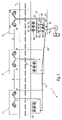
- FIG. 1 is a schematic illustration of a system for detecting a disruptive object on a stretch of road
- FIG. 2 is a flowchart of a method of detecting a disruptive object on a stretch of road.
- FIG. 3 is another embodiment of the system of FIG. 1 .
- FIG. 1 represents a system 2 for detecting the presence of a disruptive object on a road 4 .
- FIG. 1 To simplify FIG. 1 , only two successive stretches 6 and 8 of the road 4 are illustrated. The description which follows of the system 2 will be offered solely in regard to these two stretches.
- the stretches 6 and 8 are each divided into two portions respectively 6 ′ and 6 ′′, and 8 ′ and 8 ′′.
- the system 2 comprises a road traffic beacon placed at the entrance and at the exit of each stretch of road.
- the system 2 comprises a beacon 10 at the entrance of the stretch 6 , a beacon 11 common to the exit of the stretch 6 and to the entrance of the stretch 8 and a beacon 12 at the exit of the stretch 8 .
- the beacons 10 to 12 are, for example, all identical and only the beacon 12 will be described here in detail.
- the beacon 12 comprises a vertical mast 14 at the upper end of which are fixed two picture-taking apparatuses 16 and 18 .
- the apparatus 16 is turned towards the stretch 8 to take images of the portion 8 ′′ of the stretch 8 while the apparatus 18 is turned towards the following stretch of the road 4 .
- the beacon 12 also comprises a vehicle detector 20 able to detect the passage of a vehicle in proximity on the road 4 so as to count the number of vehicle exiting the stretch 8 .
- This detector is, for example, embodied with the aid of a matrix of acoustic sensors 22 . In FIG. 1 , only three acoustic sensors 22 are represented for each detector.
- the apparatuses 16 and 18 as well as the various acoustic sensors 22 are linked to a local circuit 24 for data processing.
- the circuit 24 is housed in an electrical cabinet placed at the foot of the mast 14 .
- the circuit 24 comprises:
- the circuit 24 also comprises a radio module 40 suitable for exchanging information by way of a radio link with the road traffic beacons placed upstream and downstream along the road 4 .
- a radio module 40 suitable for exchanging information by way of a radio link with the road traffic beacons placed upstream and downstream along the road 4 .
- the radio links 41 and 42 between, respectively, the beacons 10 and 11 , and 11 and 12 are represented.
- the radio module 40 is also able to establish a radio link 44 with an information transmission network 46 , in such a way as to be able to communicate with a platform 48 for supervising the road traffic on the road 4 .
- the network 46 is, for example, a telephone network.
- the platform 48 is a computer server or a set of computer servers suitable for managing the traffic on a road network comprising in particular the road 4 .
- the vehicle detectors of the beacons 10 and 11 bear the references 50 and 52 respectively.
- the vehicle detectors operate permanently, during a step 60 , to detect the passage of a vehicle in proximity to one of the beacons 10 to 12 .
- the passage of a vehicle in proximity to one of the detectors is detected by measuring with the aid of the sensors 22 the power of the sound wave generated by this vehicle.
- the power of the sound wave measured is compared with a threshold and if this threshold is exceeded then a vehicle is detected.
- each detector determines the direction of travel of the vehicle detected in such a way as to distinguish the vehicles entering or vehicles exiting the stretch, if the road 4 is a two-way road.
- the module 28 of each beacon counts, during a step 62 , the number of vehicles which have passed during this interval ⁇ T in proximity to this beacon on the basis of the data gleaned by the detector 20 .
- the number of vehicles entering the stretch 8 that were counted by the beacon 11 is transmitted, during a step 64 , to the beacon 12 by way of the radio link 42 .
- the module 28 of the beacon 12 then enumerates, during a step 66 , the vehicles simultaneously present on the stretch 8 .
- the beacon 12 calculates a result representative of the increase in the number of vehicles on the stretch 8 .
- This result is here a probability P i that a disruptive object is actually present on the stretch 8 .
- the probability P i is established as a function of the data gleaned by the detectors 20 and 52 and more precisely as faunction of the number of vehicles enumerated during step 66 .
- this probability P i is compared with an image processing activation threshold S a .
- S a is equal to 0.5. If the probability P i is less than the threshold S a , then the method returns to step 60 and the image processing module 30 is not activated or is deactivated.
- the module 34 instructs the activation, during a step 74 , of the apparatus 16 and of the modules 26 and 30 of the beacon 12 .
- the activation unit 34 also instructs the activation of the modules 26 and 30 of the beacon 11 as well as of the picture-taking apparatus of the beacon 11 turned towards the portion 8 ′ of the stretch 8 .
- the activated picture-taking apparatuses take images at regular intervals of the stretch 8 . These images are acquired by the image acquisition modules 26 and transmitted to the respective processing modules 30 of the beacons 11 and 12 .
- the processing modules 30 of the beacons 11 and 12 determine on the basis of the analysis of the images acquired, a probability P v that a disruptive object is present on the stretch 8 .
- the beacon 11 transmits, during a step 82 , the probability P v that it has determined to the beacon 12 by way of the radio link 42 .
- the beacon 12 combines the probabilities P v determined by the beacons 11 and 12 and the probability P i established by the beacon 12 , in such a way as to establish an incidents estimator E i .
- the estimator E i is compared, during a step 86 , with a predetermined alarm threshold S b . If the estimator E i is less than the threshold S b , then the method returns to step 62 .
- the beacon 12 transmits, during a step 90 , an alarm to the platform 48 by way of the link 44 and of the network 46 and then returns to step 62 .
- the platform 48 receive this alarm and acts accordingly during a step 92 .
- the platform 48 automatically instructs the displaying on a luminous signalling panel of a message indicating that a disruptive object is located on the stretch 8 .
- the sensors 22 of the beacon 12 are also used, during a step 100 , to measure the power of the ambient noise when no motor vehicle is present in proximity to the beacon. The power thus measured is then compared, during a step 102 , with the operating span 38 . If the ambient noise power measured lies within the operating span, then the method returns to step 100 .
- the system 2 toggles into a degraded operating mode.
- the unit 34 automatically and systematically instructs the activation, during a step 104 , of the apparatus 16 , of the module 26 and of the module 30 of the beacon 12 as well as of the apparatus and of the corresponding modules in the beacon 11 , in such a way as to be capable of rapidly detecting the presence of a disruptive object on the stretch 8 , by image processing.
- the image processing is used to alleviate the fact that the detector 20 is unuseable or inoperative.
- FIG. 3 represents a system 110 for detecting a disruptive object on the stretch of road 4 .
- the elements already described in regard to FIG. 1 bear the same numerical references.
- only three beacons 112 , 113 and 114 placed respectively at the location of the beacons 10 , 11 and 12 of FIG. 1 are represented.
- the beacons 112 to 114 are identical and only the beacon 114 will be described in detail.
- the beacon 114 is identical to the beacon 12 with the exception that it is devoid of any image processing module 30 .
- the processing of the images is performed in the platform 48 .
- the platform 48 comprises an image processing module 118 common to the whole set of road traffic beacons of the system 110 .
- the module 118 like the module 30 is able to establish a probability P v that a disruptive object is present on a stretch on the basis of images acquired by the picture-taking apparatuses of the beacons 112 to 114 .
- the platform 48 is here able to trigger an alarm if the probability P v combined or not with the probability P i exceeds a predetermined threshold and to act accordingly.
- the operation of the system 110 follows from the operation of the system 2 .
- the main difference resides in the fact that the images acquired by the module 26 are only transmitted to the module 118 when the probability P i established by a beacon is greater than the threshold S a .
- the activation unit 34 makes it possible to limit the band width required to transmit images from a beacon to the platform 48 .
- the presence of the activation module 34 also makes it possible to limit the calculational power necessary to execute the image processing, since it is highly improbable that the module 118 has to process inparallel the images acquired by the whole set of road traffic beacons of the system 110 .
- the acoustic sensors may be replaced with microwave radars, ultrasounds, magnetic sensors or other sensors able to detect the passage of a vehicle at a given point of a road.
- Each beacon can comprise a single picture-taking apparatus or on the contrary more than two picture-taking apparatuses.
- the calculation of the probability P i is carried out locally by the beacons.
- this calculation can be off-loaded to the platform 48 , this requiring that the numbers S(t) established by each of the beacons be transmitted in real time to the platform 48 .
- the acquisition of the images is activated permanently and the processing module alone is activated when necessary by the module 34 .
- the enumerating module establishes on the basis of the data gleaned by the detector 20 a mean number of vehicles counted, accompanied by a standard deviation for this mean.
- the activation threshold S a is dependent on the mean S m .
Landscapes
- Physics & Mathematics (AREA)
- General Physics & Mathematics (AREA)
- Traffic Control Systems (AREA)
- Analysing Materials By The Use Of Radiation (AREA)
Abstract
-
- a step (66) of enumerating the vehicles simultaneously present on the stretch of road on the basis of data gleaned by a first and a second vehicle detector placed respectively at an entrance and at an exit of this stretch, and
- a step (74) of instructing the activation of an image processing step, triggered automatically as a function of the enumeration.
Description
-
- b) a step of enumerating the vehicles simultaneously present on the stretch of road on the basis of data gleaned by a first and a second vehicle detector placed respectively at an entrance and at an exit of this stretch, and
- c) a step of instructing the activation of the image processing step, triggered automatically as a function of the enumeration of step b).
-
- a step of acquiring the images intended to be processed during the image processing step and a step of instructing the activation of the image acquisition step, triggered automatically as a function of the enumeration of step b);
- a step of calculating a result representative of an increase in the number of vehicles enumerated, this result being dependent on the number of vehicles enumerated during step b), and a step of comparing the result with a predetermined activation threshold so as to automatically trigger at least one of the instruction steps if this threshold is crossed;
- a step of calculating the result and/or the predetermined activation threshold as a function of the mean number of motor vehicles simultaneously present on this stretch observed over previous time intervals;
- a step of instructing the activation of the image processing step if one of the vehicle detectors placed at the entrance or at the exit of the stretch becomes inoperative;
- a step of measuring the ambient noise with the aid of acoustic sensors and a step of comparing the ambient noise measured with the predetermined span of ambient noise powers to determine whether the detector is inoperative;
- a step of generating an alarm signal indicating the presence of a disruptive object on the stretch of road, this generating step being triggered automatically as a function at one and the same time of results obtained during the image processing step and during the enumerating step.
-
- the automatic activation of the step of acquiring images as a function of the number of motor vehicles simultaneously present on the stretch of road also makes it possible to limit the energy consumption and to decrease the amount of information transmitted between an image acquisition module and an image processing module;
- the activation of the image processing in response to the increase in the number of vehicles enumerated makes it possible to rapidly detect a disruptive object without the image processing being activated permanently;
- the fixing of the result and/or of the predetermined activation threshold as a function of the mean number of motor vehicles simultaneously present on the stretch of road increases the robustness of the method of detection in relation to variations in the intensity of the road traffic;
- the automatic activation of the image processing step, when at least one of the vehicle detectors is inoperative, makes it possible to detect a disruptive object even though one of the vehicle detectors is not useable; and
- the combination of results obtained on the basis of the image processing and of the counting of the vehicles makes it possible to more reliably estimate the probability that a disruptive object is present on the stretch.
-
- an image processing module able to detect the presence of the disruptive object on the basis of images of the said stretch,
- at least one first and one second motor vehicle detector placed respectively at an entrance and at an exit of this stretch,
- a module for enumerating motor vehicles simultaneously present on this stretch on the basis of data gleaned by the first and second detectors, and
- a module for activating the processing module suitable for automatically triggering the activation of the processing module as a function of the enumeration established by the enumeration module.
-
- a module for acquiring the images intended to be processed by the image processing module, and the activation module (34) is also able to automatically trigger the activation of the acquisition module as a function of the enumeration established by the enumeration module;
- the motor vehicle detectors each comprise at least one acoustic sensor for detecting the passage of a motor vehicle on the basis of the sound wave generated by this vehicle, this or each sensor being intended to work in a predetermined span of ambient noise powers, the system comprises a module for establishing the power of the ambient noise, and the activation module is able to automatically activate the image processing module if the ambient noise power established is incompatible with the predetermined span of ambient noise powers.
-
- a
module 26 for acquiring the images taken by theapparatuses - a
module 28 for enumerating suitable for enumerating the vehicles detected by thedetector 20 during a given time interval vT, - a
conventional module 30 for processing the images acquired by themodule 26, suitable for automatically detecting the presence of a disruptive object on thestretch 8 on the basis of the analysis of these images, - a
module 32 for establishing the ambient noise on the basis of the measurements carried out by the sensors 22, when no vehicle is present on thestretch 8, - a
module 34 for activating theprocessing module 30 as a function of the enumeration established by themodule 28 or of ambient noise-related information established by themodule 32. Thecircuit 24 also comprises amemory 36 in which is recorded apredetermined span 38 of operation for the acoustic sensors 22. Thespan 38 defines in particular a maximum ambient noise power threshold beyond which thedetector 20 is unuseable for detecting the passage of a vehicle.
- a
S(t)=S(t−1)+N 11(t)−N 12(t)
where:
- S(t) is the number of vehicles simultaneously present on the
stretch 8 during the current time interval delta T, - S(t−1) represents the number of vehicles simultaneously present on the
stretch 8 during the previous time interval delta T, - N11(t) is the number of vehicles entering the
stretch 8 that were counted by thebeacon 11 during the current time interval delta T, and - N12(t) is the number of vehicles exiting the
stretch 8 that were counted by thebeacon 12 during the current time interval delta T.
Thereafter, thebeacon 12 calculates, during astep 68, an incident threshold Si as a function of a mean Sm, calculated over several previous time intervals delta T, of the number of vehicles simultaneously present on thestretch 8. For example, the threshold Si is equal to at least twice the mean Sm and is at least equal to 1.
If S(t)<Sm then Pi=0
If S i >S(t)≧S m then P i=(S(t)−S m)/(S i −S m)
If S(t)≧Si then Pi=1
E i =P v11 +P v12 +P i (3)
where:
- Pv11 is the probability Pv, determined by the
beacon 11, of the presence of a disruptive object, - Pv12 is the probability TPv determined by the
beacon 12, of the presence of a disruptive object, and - Pi is the incident probability established by the
beacon 12 on the basis of the data gleaned by thedetectors
Claims (11)
Applications Claiming Priority (2)
| Application Number | Priority Date | Filing Date | Title |
|---|---|---|---|
| FR0503145 | 2005-03-31 | ||
| FR0503145A FR2884018A1 (en) | 2005-03-31 | 2005-03-31 | Impeding object e.g. damaged vehicle, presence detecting method for use on road segment, involves counting vehicles present on segment and controlling automatic activation of image processing based on counting |
Publications (2)
| Publication Number | Publication Date |
|---|---|
| US20060235612A1 US20060235612A1 (en) | 2006-10-19 |
| US7460949B2 true US7460949B2 (en) | 2008-12-02 |
Family
ID=35276240
Family Applications (1)
| Application Number | Title | Priority Date | Filing Date |
|---|---|---|---|
| US11/393,925 Active 2027-05-24 US7460949B2 (en) | 2005-03-31 | 2006-03-31 | Method and system for detecting the presence of a disruptive object and activation module for this system |
Country Status (6)
| Country | Link |
|---|---|
| US (1) | US7460949B2 (en) |
| EP (1) | EP1710767B1 (en) |
| AT (1) | ATE377234T1 (en) |
| DE (1) | DE602006000189T2 (en) |
| ES (1) | ES2294775T3 (en) |
| FR (1) | FR2884018A1 (en) |
Cited By (2)
| Publication number | Priority date | Publication date | Assignee | Title |
|---|---|---|---|---|
| US9615023B2 (en) * | 2015-03-13 | 2017-04-04 | Center For Integrated Smart Sensors Foundation | Front-end event detector and low-power camera system using thereof |
| US10177598B1 (en) * | 2015-08-26 | 2019-01-08 | Mehdi Mozafari | Energy storage system |
Families Citing this family (6)
| Publication number | Priority date | Publication date | Assignee | Title |
|---|---|---|---|---|
| FR2928221B1 (en) | 2008-02-28 | 2013-10-18 | Neavia Technologies | METHOD AND DEVICE FOR MULTI-TECHNOLOGY DETECTION OF A VEHICLE |
| BE1018764A3 (en) * | 2009-05-27 | 2011-08-02 | Traficon Nv | DEVICE AND SYSTEM FOR TUNNEL DETECTION. |
| CN103063222B (en) * | 2011-10-24 | 2017-08-04 | 泰为信息科技公司 | With the navigation system and its operating method for turning to restriction scheme |
| GB2518784B (en) * | 2013-09-27 | 2015-10-21 | Thales Holdings Uk Plc | Apparatus and method for managing traffic |
| ITUB20159226A1 (en) * | 2015-12-17 | 2017-06-17 | Francesco Porzio | SYSTEM OF DETECTION AND SIGNALING OF OBSTACLES ON A PATH |
| US11151874B2 (en) * | 2020-01-23 | 2021-10-19 | Frogparking Limited | Vehicle flow monitoring system |
Citations (8)
| Publication number | Priority date | Publication date | Assignee | Title |
|---|---|---|---|---|
| EP0396432A2 (en) * | 1989-05-05 | 1990-11-07 | Golden River Limited | Monitoring apparatus |
| EP0856826A2 (en) * | 1997-02-04 | 1998-08-05 | Neil James Stevenson | A security system |
| DE19727895A1 (en) | 1997-07-01 | 1999-02-11 | Bosch Gmbh Robert | Road traffic detection device for monitoring traffic flow |
| US20020059017A1 (en) * | 2000-10-16 | 2002-05-16 | Kenichiro Yamane | Probe car control method and traffic control system |
| US20030099400A1 (en) * | 2001-11-26 | 2003-05-29 | Takahiro Ishikawa | Obstacle monitoring device using one-dimensional signal |
| EP1414000A1 (en) | 2002-10-22 | 2004-04-28 | Olindo Regazzo | Traffic control system for signalling timely any obstruction on the road |
| US20040096082A1 (en) * | 2002-08-28 | 2004-05-20 | Hiroaki Nakai | Obstacle detection device and method therefor |
| US20060025896A1 (en) * | 2004-07-28 | 2006-02-02 | Ansgar Traechtler | Coordination of a vehicle dynamics control system with a rear-wheel steering system |
-
2005
- 2005-03-31 FR FR0503145A patent/FR2884018A1/en active Pending
-
2006
- 2006-03-31 ES ES06356036T patent/ES2294775T3/en active Active
- 2006-03-31 EP EP06356036A patent/EP1710767B1/en not_active Not-in-force
- 2006-03-31 US US11/393,925 patent/US7460949B2/en active Active
- 2006-03-31 DE DE602006000189T patent/DE602006000189T2/en active Active
- 2006-03-31 AT AT06356036T patent/ATE377234T1/en not_active IP Right Cessation
Patent Citations (10)
| Publication number | Priority date | Publication date | Assignee | Title |
|---|---|---|---|---|
| EP0396432A2 (en) * | 1989-05-05 | 1990-11-07 | Golden River Limited | Monitoring apparatus |
| EP0856826A2 (en) * | 1997-02-04 | 1998-08-05 | Neil James Stevenson | A security system |
| DE19727895A1 (en) | 1997-07-01 | 1999-02-11 | Bosch Gmbh Robert | Road traffic detection device for monitoring traffic flow |
| US20020059017A1 (en) * | 2000-10-16 | 2002-05-16 | Kenichiro Yamane | Probe car control method and traffic control system |
| US20030099400A1 (en) * | 2001-11-26 | 2003-05-29 | Takahiro Ishikawa | Obstacle monitoring device using one-dimensional signal |
| US20040096082A1 (en) * | 2002-08-28 | 2004-05-20 | Hiroaki Nakai | Obstacle detection device and method therefor |
| US20050169530A1 (en) * | 2002-08-28 | 2005-08-04 | Kabushiki Kaisha Toshiba | Obstacle detection device and method therefor |
| US7132933B2 (en) * | 2002-08-28 | 2006-11-07 | Kabushiki Kaisha Toshiba | Obstacle detection device and method therefor |
| EP1414000A1 (en) | 2002-10-22 | 2004-04-28 | Olindo Regazzo | Traffic control system for signalling timely any obstruction on the road |
| US20060025896A1 (en) * | 2004-07-28 | 2006-02-02 | Ansgar Traechtler | Coordination of a vehicle dynamics control system with a rear-wheel steering system |
Cited By (2)
| Publication number | Priority date | Publication date | Assignee | Title |
|---|---|---|---|---|
| US9615023B2 (en) * | 2015-03-13 | 2017-04-04 | Center For Integrated Smart Sensors Foundation | Front-end event detector and low-power camera system using thereof |
| US10177598B1 (en) * | 2015-08-26 | 2019-01-08 | Mehdi Mozafari | Energy storage system |
Also Published As
| Publication number | Publication date |
|---|---|
| EP1710767A1 (en) | 2006-10-11 |
| ES2294775T3 (en) | 2008-04-01 |
| DE602006000189T2 (en) | 2008-08-14 |
| US20060235612A1 (en) | 2006-10-19 |
| FR2884018A1 (en) | 2006-10-06 |
| EP1710767B1 (en) | 2007-10-31 |
| ATE377234T1 (en) | 2007-11-15 |
| DE602006000189D1 (en) | 2007-12-13 |
Similar Documents
| Publication | Publication Date | Title |
|---|---|---|
| US9344856B2 (en) | Detection of false vehicle-to-vehicle emergency brake light messages | |
| JP5298712B2 (en) | Sensor abnormality detection system, method, sensor abnormality detection device, and computer program | |
| JP2006525589A (en) | Event detection system | |
| JP2003063356A (en) | Surveillance systems, central monitors, and on-board monitors | |
| RU2015143161A (en) | REDUCTION OF FALSE RADAR WARNINGS | |
| JP6856979B2 (en) | Radio interference detection system and radio interference detection method along the route | |
| CN109255957B (en) | A method and system for monitoring vehicle driving in a tunnel | |
| US7460949B2 (en) | Method and system for detecting the presence of a disruptive object and activation module for this system | |
| KR100980314B1 (en) | Hotspot Surveillance System in History | |
| KR101125275B1 (en) | Unmanned Monitoring Mathod and System | |
| KR20230070658A (en) | people counter having thermal camera and, industrial site fire detecting system therewith | |
| KR102188567B1 (en) | System for monitoring the road using 3 dimension laser scanner | |
| KR20160062259A (en) | Method, system and computer readable medium for managing abnormal state of vehicle | |
| KR20190080521A (en) | Device and method for monitoring disabled parking lot using radar | |
| CN114061645B (en) | Anomaly detection method, infrastructure sensor device, system and readable medium | |
| US20100286898A1 (en) | Apparatus for supplying road conditions | |
| JP2014120104A (en) | Traffic congestion tail detection system and traffic congestion tail detection method | |
| JP4357266B2 (en) | Radar apparatus and radar apparatus abnormality determination method | |
| KR20150125266A (en) | Incident monitoring system and method based on incident vehicle information | |
| JP2006349602A (en) | In-vehicle radar device | |
| CN106710028B (en) | Method and apparatus for testing wakeup time of unmanned vehicle | |
| JP2020149517A (en) | Traveling vehicle information collection system, traveling vehicle information collection method | |
| KR102510022B1 (en) | Apparatus and method for recognizing situation in tunnel based on radar sensor | |
| KR101202698B1 (en) | Frequency caculation method and checking apparatus for loop detector therewith | |
| JP2012068851A (en) | Road condition grasping device and road condition grasping method |
Legal Events
| Date | Code | Title | Description |
|---|---|---|---|
| AS | Assignment |
Owner name: NEAVIA, FRANCE Free format text: ASSIGNMENT OF ASSIGNORS INTEREST;ASSIGNOR:WILBROD, JEAN-HUBERT;REEL/FRAME:017831/0623 Effective date: 20060412 |
|
| STCF | Information on status: patent grant |
Free format text: PATENTED CASE |
|
| AS | Assignment |
Owner name: NEAVIA TECHNOLOGIES, FRANCE Free format text: NAME CLARIFICATION;ASSIGNOR:WILBROD, JEAN- HUBERT;REEL/FRAME:022427/0527 Effective date: 20090309 |
|
| FPAY | Fee payment |
Year of fee payment: 4 |
|
| FPAY | Fee payment |
Year of fee payment: 8 |
|
| MAFP | Maintenance fee payment |
Free format text: PAYMENT OF MAINTENANCE FEE, 12TH YR, SMALL ENTITY (ORIGINAL EVENT CODE: M2553); ENTITY STATUS OF PATENT OWNER: SMALL ENTITY Year of fee payment: 12 |