US7451678B2 - Cutting tool with grooved cutting edge - Google Patents
Cutting tool with grooved cutting edge Download PDFInfo
- Publication number
- US7451678B2 US7451678B2 US11/346,923 US34692306A US7451678B2 US 7451678 B2 US7451678 B2 US 7451678B2 US 34692306 A US34692306 A US 34692306A US 7451678 B2 US7451678 B2 US 7451678B2
- Authority
- US
- United States
- Prior art keywords
- cutting
- metal
- cutting tool
- edge
- base
- Prior art date
- Legal status (The legal status is an assumption and is not a legal conclusion. Google has not performed a legal analysis and makes no representation as to the accuracy of the status listed.)
- Expired - Lifetime, expires
Links
- 238000005520 cutting process Methods 0.000 title claims abstract description 194
- 239000002184 metal Substances 0.000 claims abstract description 135
- 229910052751 metal Inorganic materials 0.000 claims abstract description 135
- 230000036346 tooth eruption Effects 0.000 claims abstract description 26
- 239000002131 composite material Substances 0.000 claims description 47
- 239000007787 solid Substances 0.000 claims description 7
- 238000010894 electron beam technology Methods 0.000 claims description 6
- 229910000997 High-speed steel Inorganic materials 0.000 claims description 4
- 239000007790 solid phase Substances 0.000 claims description 3
- 230000003628 erosive effect Effects 0.000 claims 1
- 239000000463 material Substances 0.000 description 21
- 238000000034 method Methods 0.000 description 13
- 150000002739 metals Chemical class 0.000 description 12
- 238000003466 welding Methods 0.000 description 8
- 238000004519 manufacturing process Methods 0.000 description 5
- 230000008901 benefit Effects 0.000 description 4
- 238000007796 conventional method Methods 0.000 description 4
- 238000013016 damping Methods 0.000 description 4
- 238000010438 heat treatment Methods 0.000 description 4
- 230000009467 reduction Effects 0.000 description 4
- 229910001315 Tool steel Inorganic materials 0.000 description 3
- 238000007596 consolidation process Methods 0.000 description 3
- 230000008569 process Effects 0.000 description 3
- 238000005096 rolling process Methods 0.000 description 3
- XEEYBQQBJWHFJM-UHFFFAOYSA-N Iron Chemical compound [Fe] XEEYBQQBJWHFJM-UHFFFAOYSA-N 0.000 description 2
- 239000010953 base metal Substances 0.000 description 2
- 230000000295 complement effect Effects 0.000 description 2
- 230000006872 improvement Effects 0.000 description 2
- 238000003801 milling Methods 0.000 description 2
- 239000012255 powdered metal Substances 0.000 description 2
- 238000002360 preparation method Methods 0.000 description 2
- 238000003825 pressing Methods 0.000 description 2
- 230000005855 radiation Effects 0.000 description 2
- 239000011359 shock absorbing material Substances 0.000 description 2
- 229910000851 Alloy steel Inorganic materials 0.000 description 1
- 239000004593 Epoxy Substances 0.000 description 1
- 235000011499 Ferocactus hamatacanthus Nutrition 0.000 description 1
- 244000154165 Ferocactus hamatacanthus Species 0.000 description 1
- 229910000831 Steel Inorganic materials 0.000 description 1
- 230000009471 action Effects 0.000 description 1
- 238000005452 bending Methods 0.000 description 1
- 238000013461 design Methods 0.000 description 1
- 238000011161 development Methods 0.000 description 1
- 230000018109 developmental process Effects 0.000 description 1
- 229910003460 diamond Inorganic materials 0.000 description 1
- 239000010432 diamond Substances 0.000 description 1
- 239000000945 filler Substances 0.000 description 1
- 238000007373 indentation Methods 0.000 description 1
- 230000001939 inductive effect Effects 0.000 description 1
- 229910052742 iron Inorganic materials 0.000 description 1
- 230000005923 long-lasting effect Effects 0.000 description 1
- 239000011159 matrix material Substances 0.000 description 1
- 229910001092 metal group alloy Inorganic materials 0.000 description 1
- 229920000620 organic polymer Polymers 0.000 description 1
- 230000010355 oscillation Effects 0.000 description 1
- 239000002994 raw material Substances 0.000 description 1
- 238000010008 shearing Methods 0.000 description 1
- 229910000679 solder Inorganic materials 0.000 description 1
- 239000007858 starting material Substances 0.000 description 1
- 239000010959 steel Substances 0.000 description 1
- 238000005482 strain hardening Methods 0.000 description 1
- 230000009466 transformation Effects 0.000 description 1
- XLYOFNOQVPJJNP-UHFFFAOYSA-N water Substances O XLYOFNOQVPJJNP-UHFFFAOYSA-N 0.000 description 1
Images


Classifications
-
- B—PERFORMING OPERATIONS; TRANSPORTING
- B23—MACHINE TOOLS; METAL-WORKING NOT OTHERWISE PROVIDED FOR
- B23D—PLANING; SLOTTING; SHEARING; BROACHING; SAWING; FILING; SCRAPING; LIKE OPERATIONS FOR WORKING METAL BY REMOVING MATERIAL, NOT OTHERWISE PROVIDED FOR
- B23D61/00—Tools for sawing machines or sawing devices; Clamping devices for these tools
- B23D61/12—Straight saw blades; Strap saw blades
- B23D61/121—Types of set; Variable teeth, e.g. variable in height or gullet depth; Varying pitch; Details of gullet
-
- B—PERFORMING OPERATIONS; TRANSPORTING
- B23—MACHINE TOOLS; METAL-WORKING NOT OTHERWISE PROVIDED FOR
- B23D—PLANING; SLOTTING; SHEARING; BROACHING; SAWING; FILING; SCRAPING; LIKE OPERATIONS FOR WORKING METAL BY REMOVING MATERIAL, NOT OTHERWISE PROVIDED FOR
- B23D61/00—Tools for sawing machines or sawing devices; Clamping devices for these tools
- B23D61/12—Straight saw blades; Strap saw blades
-
- Y—GENERAL TAGGING OF NEW TECHNOLOGICAL DEVELOPMENTS; GENERAL TAGGING OF CROSS-SECTIONAL TECHNOLOGIES SPANNING OVER SEVERAL SECTIONS OF THE IPC; TECHNICAL SUBJECTS COVERED BY FORMER USPC CROSS-REFERENCE ART COLLECTIONS [XRACs] AND DIGESTS
- Y10—TECHNICAL SUBJECTS COVERED BY FORMER USPC
- Y10T—TECHNICAL SUBJECTS COVERED BY FORMER US CLASSIFICATION
- Y10T83/00—Cutting
- Y10T83/04—Processes
-
- Y—GENERAL TAGGING OF NEW TECHNOLOGICAL DEVELOPMENTS; GENERAL TAGGING OF CROSS-SECTIONAL TECHNOLOGIES SPANNING OVER SEVERAL SECTIONS OF THE IPC; TECHNICAL SUBJECTS COVERED BY FORMER USPC CROSS-REFERENCE ART COLLECTIONS [XRACs] AND DIGESTS
- Y10—TECHNICAL SUBJECTS COVERED BY FORMER USPC
- Y10T—TECHNICAL SUBJECTS COVERED BY FORMER US CLASSIFICATION
- Y10T83/00—Cutting
- Y10T83/929—Tool or tool with support
- Y10T83/9319—Toothed blade or tooth therefor
- Y10T83/9324—With additional cutting means
Definitions
- This invention relates cutting tools, and in particular, to saw blades having novel teeth geometries for improved cutting.
- saw blade nowadays usually comprise a relatively tough metal base with high bending fatigue strength and a cutting-edge band of a high-speed steel that is less tough but highly wear resistant.
- the cutting-edge band is of such a width that at least the tips of the cutting teeth of the saw band or blade, or even the cutting teeth as a whole, can be cut out from it.
- the cut surface can be rough or uneven in those instances where the cutting edge becomes dull or the shape and orientation of the cutting teeth are not optimal.
- cutting chips can accumulate at the cutting surfaces, thereby clogging the cutting path and impeding subsequent cutting.
- the present invention provides a cutting with superior cutting and wear-resistant properties.
- a cutting tool in one aspect of the present invention, includes a base made of metal having a plurality to cutting teeth along an edge of the base, wherein at least one cutting tooth has at least one notch in the cutting edge of the at least one cutting tooth.
- the base has a first thickness at a first edge and a tapered region on the opposing edge of the base extending into and through an interior portion of the cutting edge member of the cutting tool, and at least one edge member comprised of a second metal is located adjacent to and forms a metallurgical bond with a surface of the tapered edge region of the base.
- a cutting tool including a base made of metal and an edge member having a plurality to cutting teeth, said edge member joined to the base along an edge of the base.
- the cutting tooth is a composite including at least first and second metals, wherein the first metal is softer than the second metal, and the first softer metal is flanked by the second harder metal and a groove is introduced during use by preferential wearing of the first, softer metal.
- a method of making a cutting tool having a base and a plurality of cutting teeth along an edge of the base includes introducing a groove running longitudinally along the length of the tool in the cutting edge of the cutting teeth.
- the notch is machined into the cutting edge, or the notch is formed during use by preferential wearing of the first, softer metal.
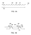
- FIG. 1A is a side view
- FIG. 1B is a fragmentary perspective view of a cutting tool according to one or more embodiments of the invention.
- FIGS. 2A-2D are cross-sectional illustrations of various embodiments of the notch geometry used in cutting teeth of a cutting tool according to one or more embodiments of the present invention.
- FIG. 3A is a cross-sectional view of a conventional welded article and 3 B is a cross-sectional view of a bonded article having a notched cutting edge according to one or more embodiments of the present invention showing the shear line of the bond.
- FIG. 4 is a cross-sectional illustration of one or more embodiments of the composite metal article of the invention in which the edge member has a plurality of alternating layers of hard cutting tool metal and a more flexible, supporting metal.
- FIGS. 5 and 6 illustrate notched tooth cutting tools according to one or more embodiments of the present invention.
- FIG. 7 illustrates the preparation of a composite metal cutting tool and shows an assembled composite of two dissimilar metals (A) prior to bonding, (B) after at least one consolidation step (arrows indicate applied pressure), (C) after additional consolidation steps, and (D) after slitting.
- FIGS. 8A through 8C illustrate the preparation and use of a composite metal wire to prepare a cutting tool of one or more embodiments of the present invention.
- the present invention provides an improved cutting article having a novel cutting surface.
- Cutting tool 100 of the present invention is shown in side view in FIG. 1A .
- the cutting tool 100 includes a base 110 and an edge member 128 running along the length of the base 110 .
- a finished product e.g., a saw blade, includes cutting teeth 140 cut or machined in the edge member 128 of the cutting tool.
- FIG. 1B is a fragmentary perspective view of the cutting tool 100 .
- Cutting teeth 140 include a notch or recess 150 in the cutting edge 160 .
- the sloping or recessed region between cutting edges 160 is referred to as the gullet 175 . (The cutting edge and the gullet may not be drawn to scale).
- a cutting tooth including a notch, groove, or indentation in the cutting edge increases the useful life of the tool, reduces shearing off of the cutting teeth and improves cutting performance.
- the lifetime of the tool is evaluated, in part, by determining the extent of tooth strippage over time.
- the “cutting surface” of the cutting tool includes the entire surface that presents itself to and engages with the object to be cut and includes the gullet, cutting edge and the side surfaces.
- “cutting edge” means the uppermost portion of the cutting surface that engages with the object to be cut and that contains the notch.
- a “cutting corner” is formed at the junction of the cutting edge, sloping gullet and the side (or notch) surfaces. The number and location of the cutting corners may play a role in the tool's cutting performance.
- the base 110 and the edge member 128 are integral, e.g., a single piece, and made from the same material.
- the base and edge member are made from different materials, for example, the base is made from a first tough metal and the edge member is made from a second hard metal.
- the base is a metal having desirable properties of mechanical and thermal stability, for example, under the conditions typically encountered in sawing or cutting operations.
- the metal base can be any hot or cold rolled metal or metal alloy that is tough and spring-like. The metal base exhibits flexibility, and metals that exhibit flexibility, e.g., spring metals, can be used in the present invention.
- the second metal used as the cutting edge is harder or more wear-resistant than the first metal.
- the edge member is a wear-resistant metal; for example, the edge member is made from a metal capable of withstanding the abrasive conditions typically encountered by the cutting edge under sawing or cutting operations.
- the edge member metal can be one or more high speed steels, including powdered metals.
- high speed steels include Matrix II, M2, M42, M51, M3 Type 1, M3 Type 2, and the like.
- the cutting tool includes at least one tooth having at least one notch or recess in the cutting edge; however, no other limitations are necessary.
- the cutting teeth can be of any conventional shape and geometry, as are dictated by the intended cutting application.
- the cutting teeth can be arranged in any way desired along the cutting surface.
- the cutting tool may include one or more notched teeth and/or may include a combination of notched and un-notched teeth.
- the teeth can be in or out of plane from the base, as is needed by a particular cutting application. In short, one is free to design the cutting tool as is most appropriate for a particular cutting application. Having determined the appropriate arrangement for the cutting teeth, the present invention improves the cutting edge by providing a notch or depression in the cutting edge.
- the cutting tool of the present invention includes composite saws (bimetallic saws) and those fabricated from a single metal.
- the cutting tool of the present invention includes conventional welded bimetallic saws and composite metal saws prepared according to one or more embodiments of the present invention.
- the blade is a toothed blade, e.g., a saw blade such as hand and powered hacksaw, hole saw, jigsaw, reciprocating saw and band saw blades.
- a blade can be welded, e.g., butt-welded, to form a band saw blade.
- the notch is longitudinally oriented in the cutting edge of the tooth, that is, in the cutting direction.
- the notch of the cutting tooth can have a variety of geometries, as are shown in the non-limiting examples of FIGS. 2A-2D .
- FIG. 2A shows a cutting tooth 200 in cross-section having a square or rectangular slot 215 .
- the notch is defined by the notch width W 2 and notch depth D 1 .
- the notch is also defined relative to the total width W 1 of the cutting tooth.
- the notch width is in the range of about 5-50% collectively of the total width of the cutting edge.
- the notch width is in the range of about 0.005-0.020′′.
- the sharp angular sides of the notch provide additional cutting corners 210 , e.g., there are now four cutting corners instead of two.
- the increase in the amount of cutting corners may play a role in the observed improvement in cutting performance.
- Two or more notches 220 can be used, as is shown for cutting tooth 225 in FIG. 2B .
- This embodiment significantly increases the number of cutting corners of the cutting surface.
- the notch can be a v-notch 230 or a rounded notch 240 , as shown in FIGS. 2C and 2D , respectively.
- the cavity defined by the notch contains a soft metal, organic polymer or other shock absorbing material.
- a soft metal such as solder or base metal or other shock absorbing material such as epoxy is introduced into the notch.
- the filler material can act to dampen harmonic vibrations that may occur during initial use, before the teeth are “broken in”. Harmonic oscillations are particularly common in teeth having a high aspect ratio, i.e., a deep notch.
- the damping material is selected to be a material that wears readily with a few operating cycles of the saw. It has been observed in some cutting tools, that the fill materials wear away slowly and in proportion with the wearing of the cutting edge.
- a particular feature of the filled-notch embodiment of the present invention is that the notch is shallow and thereby retains much of the structural stability of the un-notched tooth; however, the cutting action of the cutting tooth continually wears away or “renews” the notch as the cutting tool is used. Thus, improved cutting performance is observed throughout the entire cutting life of the tool.
- the notch can be introduced into the cutting tooth using a variety of methods.
- the notch can be machined into the cutting teeth of conventional cutting tools, such as single metal, powdered metal blade or a composite metal blade formed using conventional welding, e.g., electron beam welding, techniques.
- the notch is introduced into the cutting teeth of the blade using conventional tools such as a milling cutter, abrasive wheel, diamond saw, water jet, laser and the like.
- the different cutting techniques provide a range of cutting precision and notch characteristics. Thus, different cutting techniques are selected depending on the desired width and shape of the notch, among other characteristics.
- the cutting tool is a conventional single component saw blade, and the notch is introduced into the cutting edge using conventional methods.
- the cutting is a composite cutting tool including a tough metal base and a harder metal cutting edge.
- Composite saw blades that is, saw blades made up of two or more dissimilar materials, have been prepared by welding a thin strip of cutting tool steel to an edge of a flexible alloy steel backer. Common welding techniques are electron beam welding and laser welding.
- a conventionally welded cutting tooth 300 including the notch 305 of the present invention is shown in FIG. 3A .
- a shear line 310 indicates the point at which the edge is conventionally welded to base 320 . The notch is introduced into the cutting tooth using conventional methods.
- the composite metal cutting tools contain of cutting teeth formed from a combination of a hard cutting tool metal and a softer, supporting metal, which inherently provide a notched cutting tooth.
- the cutting edge presented to a surface to be cut includes alternating regions of hard cutting tool metal and softer metal.
- the soft metal can be provided in the form of a metal-filled notch in the harder cutting tool metal.
- FIG. 3B illustrates a composite metal cutting tool of one or more embodiments of the present invention.
- the base metal extends upwards from the base 340 and towards the cutting edge in an interior location of the cutting tool.
- the metal base forms an extended taper 345 that serves to define the recess 325 between two faces 326 , 327 of the cutting tooth.
- the notch is formed by positioning a softer material between two faces of a cutting tooth.
- Notch 325 may be introduced during use as the first few cutting cycles preferentially erode the softer metal (or other material) of the area.
- a metallurgical bond 330 is formed between the base and cutting teeth of the composite cutting tool. The length (and related area) of the bond is greater for the cutting tool shown in FIG. 3B than for the that shown in FIG. 3A , thereby providing additional advantages, e.g., the composite cutting tool would be more durable, long lasting and more resistant to shear failure.
- a cutting edge 400 of a composite cutting tool 410 as shown in FIG. 4 includes a plurality of alternating layers of hard cutting tool metal 420 and a more flexible, supporting metal 430 .
- the innermost section 440 represents the thinned, tapered section of the metal base.
- the metal used for the flexible, supporting metal sections 430 can be the same as or different from the metal of the metal base 440 .
- the metal components of the cutting edge are metallurgically bonded at shared surfaces.
- the thickness of the flexible, supporting metal sections 430 can be the same as or different from the thickness of the innermost section 440 .
- FIG. 4 illustrates a composite metal article having three sections 430 , 440 , 430 ′ of flexible, supporting metal of varying thicknesses. The number, thickness and location of the different metal regions in the edge member are selected to provide a desired property in the article.
- the cutting tool is a hybrid article including a composite metal cutting strip that is welded, after fabrication, to a metal base. Cutting teeth are then cut into the composite metal cutting edge so that the alternating layers of cutting tool steel and soft metal provides the cutting edges and notches of the present invention.
- FIG. 5 shows a hybrid saw blade 545 using a conventional base 550 .
- a composite metal cutting edge 560 includes a solid state bonded composite strip of alternating layers of hard cutting tool steel 565 and softer supporting metal 570 . Notch 575 is formed in the soft supporting metal.
- the composite metal cutting edge is then attached at weld line 580 to the base using conventional welding techniques.
- the cutting edge includes alternating regions or sections of hard and soft metal that have been solid state bonded to each other as shown in FIG. 3B , FIG. 4 and FIG. 5 .
- the material wears away only so far as to form a recess in the damping material (and thereby expose the new cutting edges of the cutting tool).
- the soft metal regions wear away after only a few operating cycles of the blade and are recessed below the level of the hard cutting tool metal to form a shallow notch in the cutting surface. This provides additional advantages to the solid state bonded composite metal articles of the present invention, since the soft metal wears away as the cutting tool surface does so that the notch is continually being formed.
- FIG. 6 shows a notched tooth cutting tool 600 prepared by mill cutting a 0.008′′ wide ⁇ 0.010′′ deep rectangular notch 610 into a cutting tooth of a conventional composite saw blade.
- the base 620 of the saw blade (0.042′′ thick) was made from D6A; and a M42 cutting strip 630 (0.060′′ wide) was electron beam welded to an edge of the base.
- Electron beam weld 640 is denoted by a broad line to illustrate the wide heat-affected region of the weld.
- Cutting teeth (not observable in this view) were cut into the cutting strip and the notch was cut with a 0.006′′ wide milling cutter before the tooth was set (oriented at the predetermined cutting angle).
- the tool was used under standard cutting conditions and the performance of the blade was compared to a comparable notch-less blade.
- the notched cutting tool demonstrated an extended cutting life compared to conventional notch-less blades. For example, the cutting life can be 25% or greater, even many-fold greater, depending upon the particular application. Improved cutting was observed in the notched blade until the cutting tooth wore down to the notch gullet base. Without a damping material, the saw blade vibrated noticeably during an initial breaking in period of the blade. Adding a damping material in the notch significantly reduced the vibration.
- the notch provides additional cutting surfaces (corners) for improved cutting by chip breaking.
- the notch reduces the chip size of the sawn material and provides and additional clearance area (in the notch) for its removal from the cutting surface. Small chips are easier to clear, and the more efficient removal of the chips reduces wear on the cutting tooth and improves cutting performance.
- the composite metal cutting tools of the present invention are prepared by heating an assembly of dissimilar metal components under pressure to form a bonded article, a process known as solid phase bonding.
- the composite assembly includes a metal base, such as a sheet or strip, having at least one depression or groove positioned longitudinally on one or both sides of the metal base that is capable of receiving an elongated metal element or wire.
- the wire can be of any shape, and is selected based upon any number of factors, including raw material availability, ease of manufacture, and the desire to complement the shape of the longitudinal depression of the metal base.
- An exemplary composite assembly 700 including a metal base 710 and elongated elements 720 , 725 positioned in depressions 730 , 735 , respectively, of the metal base 710 is shown in cross-section in FIG. 7A .
- the composite assembly is then heated under pressure to bring the metal base and the elongated elements into intimate contact and to form a metallurgical bond between the component metals.
- the composite assembly is first heated to a temperature that is above room temperature and below the temperature of any metallurgical transformation (T m ) of any of the metals of the composite assembly and then passed through a pair of rolls (a “mill roll”) to exert bonding pressure and to reduce the article thickness.
- FIG. 7B is an illustration of the article 745 at an intermediate point during the heating and rolling process.
- the insert wires 720 , 725 are pressed against and into the metal base.
- the metal base is also being reduced in thickness. The greater the thickness reduction of the metal base (expressed as % reduction), the greater the forces experienced at the interface between the metal components.
- the wire size and shape and metal sheet thickness and groove size and shape relate to the bonding forces experienced by the composite assembly, and at the point where the insert wire(s) is introduced into the base groove, the large reduction forces favor stronger solid state bonding.
- temperatures can range from about 800 to about 1600° F., or in some embodiments from about 1000 to about 1550° F. Heating can be accomplished using any conventional method.
- the composite assembly is heated using inductive or electrical resistance heating.
- the heat is supplied by a form of radiation, for example, laser radiation.
- the pressure can be generated using any conventional method.
- pressure is generated using a rolling mill or a turks head.
- Pressure is a function of many variables including, but not limited to, roll diameter, material deformation resistance (hardness), metal thickness, and the coefficient of friction between the roll and the metal being rolled, and the forces generated in rolling are well known in the industry.
- the addition of a hard insert wire, and in particular the addition of two wires stacked one on top of the other above and below the metal base causes higher pressure at the point of contact—the specific location where high pressures are desired to improve bonding.
- the additional thickness locally due to the presence of the elongated element provides additional pressure for improved bonding during the solid phase bonding operation.
- FIG. 7C illustrates a final bonded article 758 , in which the pressure has forced the second metal of the wire insert into the metal base and the article surface is substantially flat.
- the contact area between the wire and the base has increased considerably during the bonding process due to thickness reduction and article elongation. Increased contact area provides a large bonding interface and contributes to the high quality of the bond.
- the metal base 710 has thinned considerably in a bonding area 748 so that only a thin strip 740 of the metal base is found between the upper and lower regions 750 , 755 arising from the former insert wires.
- the metal base 710 includes a tapered section 740 that is in contact with edge members 750 , 755 on opposing surfaces the thinned, tapered section 740 .
- Edge members 750 , 755 are tapered complementary to the taper of section 740 , so that the article surface is flat.
- the taper may be linear or curved, or a more complex geometry resulting from material flow during fabrication.
- the edge members 750 , 755 and the thinned, tapered section 740 of the base 710 form a strong, i.e., metallurgical, bond at the opposing surfaces.
- the method of one or more embodiments of the invention provides a bonded article of a desired thickness.
- the starting materials can be thicker than those used in conventional electron beam welding processes, yet final thickness is achieved in fewer steps and less time, resulting in a significant savings in cost and materials.
- Wire 800 includes a metal 810 , for example one that is similar to or the same as the metal used for the metal base, and a dissimilar metal 820 .
- Metal 820 is harder than metal 810 and is located at an outer surface so that the harder metal provides increased wear resistance to the composite.
- the component metals are arranged in alternating regions and the metal regions are bonded at their interfaces.
- FIG. 8B illustrates a composite assembly 850 using the composite metal wire 800 and a metal base 855 . It is desired that the composite wire is aligned in a plane of the metal base and remains so aligned during consolidation and bonding.
- the composite wire 800 nests or fits snugly into a groove 825 of the metal base 855 .
- the composite wire is of a shape, e.g., trapezoidal and the like, that discourages rotation of the composite wire within the groove.
- FIG. 8C illustrates the final composite metal article 860 after the heat and pressure treatment of the present invention.
- the bonded region 865 includes alternating layers of metals 810 and 820 disposed in a bonding region 865 of the metal base.
- the thus-obtained composite sheet is slit vertically through the central section of the bonding region 865 to reveal an edge of alternate layers of hard metal sections ( 820 ) and flexible supporting metal ( 810 , 855 ).
- An exemplary resultant article is shown in FIG. 4 .
Landscapes
- Engineering & Computer Science (AREA)
- Mechanical Engineering (AREA)
- Cutting Tools, Boring Holders, And Turrets (AREA)
- Drilling Tools (AREA)
Abstract
Description
Claims (12)
Priority Applications (1)
| Application Number | Priority Date | Filing Date | Title |
|---|---|---|---|
| US11/346,923 US7451678B2 (en) | 2002-07-29 | 2006-02-03 | Cutting tool with grooved cutting edge |
Applications Claiming Priority (2)
| Application Number | Priority Date | Filing Date | Title |
|---|---|---|---|
| US10/207,415 US7017465B2 (en) | 2002-07-29 | 2002-07-29 | Cutting tool with grooved cutting edge |
| US11/346,923 US7451678B2 (en) | 2002-07-29 | 2006-02-03 | Cutting tool with grooved cutting edge |
Related Parent Applications (1)
| Application Number | Title | Priority Date | Filing Date |
|---|---|---|---|
| US10/207,415 Continuation US7017465B2 (en) | 2002-07-29 | 2002-07-29 | Cutting tool with grooved cutting edge |
Publications (2)
| Publication Number | Publication Date |
|---|---|
| US20060191396A1 US20060191396A1 (en) | 2006-08-31 |
| US7451678B2 true US7451678B2 (en) | 2008-11-18 |
Family
ID=30770428
Family Applications (2)
| Application Number | Title | Priority Date | Filing Date |
|---|---|---|---|
| US10/207,415 Expired - Lifetime US7017465B2 (en) | 2002-07-29 | 2002-07-29 | Cutting tool with grooved cutting edge |
| US11/346,923 Expired - Lifetime US7451678B2 (en) | 2002-07-29 | 2006-02-03 | Cutting tool with grooved cutting edge |
Family Applications Before (1)
| Application Number | Title | Priority Date | Filing Date |
|---|---|---|---|
| US10/207,415 Expired - Lifetime US7017465B2 (en) | 2002-07-29 | 2002-07-29 | Cutting tool with grooved cutting edge |
Country Status (8)
| Country | Link |
|---|---|
| US (2) | US7017465B2 (en) |
| EP (1) | EP1545843A4 (en) |
| JP (1) | JP2005534532A (en) |
| CN (1) | CN100376370C (en) |
| AU (1) | AU2003253796A1 (en) |
| BR (2) | BRPI0313042B1 (en) |
| RU (1) | RU2319607C2 (en) |
| WO (1) | WO2004011213A1 (en) |
Cited By (8)
| Publication number | Priority date | Publication date | Assignee | Title |
|---|---|---|---|---|
| US20080280157A1 (en) * | 2002-07-29 | 2008-11-13 | William Engineering Llc | Composite metal article and method of making |
| US20170021459A1 (en) * | 2013-11-25 | 2017-01-26 | Voestalpine Precision Strip Gmbh | Method for producing a preliminary material for a machining tool, and corresponding preliminary material |
| US20170157713A1 (en) * | 2013-11-25 | 2017-06-08 | Voestalpine Precision Strip Gmbh | Method for producing a preliminary material for a machining tool, and corresponding preliminary material |
| US9731365B2 (en) | 2011-12-07 | 2017-08-15 | Irwin Industrial Tool Company | Saw blade with tooth form projection |
| US10166612B2 (en) | 2016-08-26 | 2019-01-01 | Irwin Industrial Tool Company | Tooth formations and arrangement for a saw blade |
| US10537951B2 (en) | 2017-08-16 | 2020-01-21 | Black & Decker Inc. | Band saw blade for cutting structural workpieces |
| US10648051B2 (en) | 2015-04-24 | 2020-05-12 | Kondex Corporation | Reciprocating cutting blade with cladding |
| US11440111B2 (en) | 2020-08-17 | 2022-09-13 | Bmic Llc | Method of using a blade configured to reduce residual foam dust |
Families Citing this family (35)
| Publication number | Priority date | Publication date | Assignee | Title |
|---|---|---|---|---|
| US7017465B2 (en) * | 2002-07-29 | 2006-03-28 | L.S. Starrett Company | Cutting tool with grooved cutting edge |
| DE20308797U1 (en) * | 2003-05-28 | 2003-08-28 | C. & E. Fein GmbH & Co KG, 70176 Stuttgart | Saw with a rotating oscillating drive movement and saw blade therefor |
| JP2007090442A (en) * | 2005-09-26 | 2007-04-12 | Fujifilm Corp | Cutting blade |
| US20070160430A1 (en) * | 2006-01-11 | 2007-07-12 | Yih Troun Enterprise Co., Ltd. | Milling cutter |
| US20070163416A1 (en) * | 2006-01-13 | 2007-07-19 | The M. K. Morse Company | Circular saw blade |
| US20100011594A1 (en) * | 2008-07-15 | 2010-01-21 | Wysk Mark J | Composite Saw Blades |
| US20110119934A1 (en) * | 2008-07-25 | 2011-05-26 | Bertsch Matthew T | Band saw |
| US20100158649A1 (en) * | 2008-12-23 | 2010-06-24 | Schwing Bioset, Inc. | Silo with reciprocating frame having composite blade |
| CN101614888B (en) * | 2009-07-14 | 2011-01-19 | 友达光电(苏州)有限公司 | Cutting tool for conductive adhesive films |
| CN102883848A (en) * | 2010-02-25 | 2013-01-16 | 技术材料公司 | Methods for creating side-by-side metallic bonds between different materials using solid-phase bonding and the products produced thereby |
| EP2564966B1 (en) | 2010-04-22 | 2017-04-12 | Milwaukee Electric Tool Corporation | Saw blade |
| US10189099B2 (en) | 2010-04-22 | 2019-01-29 | Milwaukee Electric Tool Corporation | Saw Blade |
| US20120042765A1 (en) | 2010-08-20 | 2012-02-23 | Kazda Austin J | Reciprocating saw blade |
| RU2460615C1 (en) * | 2011-02-15 | 2012-09-10 | Юрий Михайлович Ермаков | Slabbing cutter |
| WO2012142194A2 (en) * | 2011-04-11 | 2012-10-18 | Rel, Inc. | Composite cutting blade |
| USD841417S1 (en) | 2011-04-22 | 2019-02-26 | Milwaukee Electric Tool Corporation | Saw blade |
| DE102011076630A1 (en) * | 2011-05-27 | 2012-11-29 | Robert Bosch Gmbh | parting tool |
| DE102011078488A1 (en) * | 2011-07-01 | 2013-01-03 | Robert Bosch Gmbh | Tool |
| US9579732B2 (en) | 2012-07-18 | 2017-02-28 | Milwaukee Electric Tool Corporation | Hole saw |
| EP2939779A1 (en) * | 2014-04-30 | 2015-11-04 | Böhler-Uddeholm Precision Strip GmbH | Bimetallic saw |
| CH711822A1 (en) * | 2015-11-30 | 2017-05-31 | Reed Electronics Ag | Device for welding thermoplastic hoses. |
| CN105499705A (en) * | 2016-02-24 | 2016-04-20 | 湖南泰嘉新材料科技股份有限公司 | Band saw blade |
| CN106041210B (en) * | 2016-05-12 | 2018-08-03 | 湖北华鑫科技股份有限公司 | Novel diamond band is sawed |
| CN106041209B (en) * | 2016-05-12 | 2018-08-03 | 湖北华鑫科技股份有限公司 | Novel and multifunctional band-saw diamond |
| CN110650829A (en) | 2017-05-16 | 2020-01-03 | 米沃奇电动工具公司 | Saw blade |
| CN107116268B (en) * | 2017-07-06 | 2019-06-07 | 西南大学 | A kind of broached-tooth design |
| US10814413B2 (en) * | 2017-09-05 | 2020-10-27 | Simonds Saw Llc | Saw blade having ramp elements with a variable curve geometry |
| CN107824818A (en) * | 2017-11-17 | 2018-03-23 | 中山市园丰精密刃具有限公司 | A kind of volume cutting ring and its production technology for processing automobile key |
| US20190210150A1 (en) * | 2018-01-11 | 2019-07-11 | Hangzhou Great Star Industrial Co., Ltd. | Cutting assembly and method for manufacturing same |
| CN216028284U (en) | 2018-07-10 | 2022-03-15 | 米沃奇电动工具公司 | Hole saw |
| USD920065S1 (en) * | 2018-12-06 | 2021-05-25 | Robert Bosch Gmbh | Saw blade |
| CN113924180A (en) | 2019-06-20 | 2022-01-11 | 米沃奇电动工具公司 | Hole saw with circular side wall opening |
| USD958855S1 (en) | 2019-12-09 | 2022-07-26 | Milwaukee Electric Tool Corporation | Hole saw |
| KR20230026976A (en) * | 2020-06-22 | 2023-02-27 | 스미또모 덴꼬오 하드메탈 가부시끼가이샤 | Tools and methods of manufacturing tools |
| JP7254317B1 (en) | 2022-05-18 | 2023-04-10 | 株式会社オリジン | Tip part for tip, tip for cutting tool, and method for manufacturing tip for cutting tool |
Citations (75)
| Publication number | Priority date | Publication date | Assignee | Title |
|---|---|---|---|---|
| SU307877A1 (en) | А. В. Пол ченко , Л. Б. Рогинский Государственный всесоюзный научно исследовательс технологический институт ремонта , эксплуатации машинно тракторного парка | |||
| US1434047A (en) | 1918-08-21 | 1922-10-31 | Anatmos Metals And Furnace Cor | Method of uniting hard steel alloys to softer steel bars |
| GB377146A (en) | 1932-02-24 | 1932-07-21 | Henry G Thompson & Son Co | Improvements in saw blades |
| US2226944A (en) | 1938-10-27 | 1940-12-31 | Bell Telephone Labor Inc | Method of bonding dissimilar metals |
| US2686439A (en) | 1948-04-27 | 1954-08-17 | Thoger G Jungersen | Method of making cutting tools |
| US2706328A (en) | 1950-11-21 | 1955-04-19 | Karmazin John | Method and blank for making tubing |
| US2941282A (en) | 1955-01-21 | 1960-06-21 | Howard A Fromson | Decorative aluminum product |
| US2961762A (en) | 1957-03-06 | 1960-11-29 | Texas Instruments Inc | Solid phase strip inlay bonding |
| US3034379A (en) | 1959-06-15 | 1962-05-15 | Sandvikens Jernverks Ab | Composite steel saw blades and method of making the same |
| USRE25434E (en) | 1959-04-20 | 1963-08-13 | Abrasive cutting devices | |
| US3162187A (en) | 1961-12-11 | 1964-12-22 | Christensen Diamond Prod Co | Diamond saw blades |
| US3315548A (en) | 1964-12-07 | 1967-04-25 | Contour Saws | Method of making band saw blade |
| US3371393A (en) | 1966-03-04 | 1968-03-05 | Grassmann Gunther | Hot-saw blade |
| US3468015A (en) | 1966-10-31 | 1969-09-23 | Texas Instruments Inc | Process of manufacturing strip contact material by inlaying peripherally clad noble-metal strip |
| US3593600A (en) | 1969-04-29 | 1971-07-20 | Continental Can Co | Band saw blade apparatus and methods |
| US3616982A (en) | 1968-05-22 | 1971-11-02 | Texas Instruments Inc | Metal cladding |
| US3702497A (en) | 1971-01-07 | 1972-11-14 | Polymetallurgical Corp | Manufacture of clad metals |
| US3707617A (en) | 1971-06-14 | 1972-12-26 | Texas Instruments Inc | Apparatus for making edgelay thermostatic bimetals |
| US3714701A (en) | 1971-01-04 | 1973-02-06 | Polymetallurgical Corp | Manufacture of clad metals |
| US3762007A (en) | 1971-01-04 | 1973-10-02 | Polymetallurgical Corp | Rotary hollow milling cutter |
| US3789498A (en) * | 1971-11-01 | 1974-02-05 | Ambac Ind | Method of diffusion bonding |
| US3793700A (en) * | 1972-09-01 | 1974-02-26 | Gen Dynamics Corp | Method of reshaping metal matrix composite material |
| US3888663A (en) * | 1972-10-27 | 1975-06-10 | Federal Mogul Corp | Metal powder sintering process |
| SU474420A1 (en) | 1972-11-22 | 1975-06-25 | Московский Завод По Обработке Специальных Сплавов | The method of obtaining bimetallic tape |
| US3894675A (en) | 1974-01-24 | 1975-07-15 | Kabel Metallwerke Ghh | Method and apparatus for making copper clad steel wire |
| US3927817A (en) * | 1974-10-03 | 1975-12-23 | Rockwell International Corp | Method for making metallic sandwich structures |
| US3930426A (en) | 1972-04-20 | 1976-01-06 | Stora Kopparbergs Bergslags Aktiebolag | Method of making a saw blade |
| DE2438601A1 (en) | 1974-08-10 | 1976-02-26 | Winter & Sohn Ernst | Rotating cut-off tools such as slitting wheels - where hard outer layer covers diamond or boron nitride grains in binder matrix |
| US4068976A (en) | 1976-06-29 | 1978-01-17 | Kennametal Inc. | Cutting insert configuration |
| US4125936A (en) | 1977-09-01 | 1978-11-21 | Rozmus John J | Composite strip for fabricating spring contacts |
| US4187754A (en) | 1978-09-21 | 1980-02-12 | Beaty Loma B | Noise dampened rotary saw blade |
| US4232096A (en) | 1976-12-17 | 1980-11-04 | Uddeholms Aktiebolag | Composite steel material and composite steel tool made from this material |
| JPS58151978A (en) | 1982-03-02 | 1983-09-09 | Hitachi Cable Ltd | Manufacturing device for composite wire material |
| US4409296A (en) | 1979-05-09 | 1983-10-11 | Allegheny Ludlum Steel Corporation | Rapidly cast alloy strip having dissimilar portions |
| US4461268A (en) | 1982-01-04 | 1984-07-24 | Jiro Inoue | Diamond saw |
| US4463645A (en) | 1983-02-22 | 1984-08-07 | Speedcut, Inc. | Circular saw |
| US4484959A (en) | 1981-07-17 | 1984-11-27 | Creusot-Loire | Process for the production of a composite metal part and products thus obtained |
| JPS606287A (en) | 1983-06-27 | 1985-01-12 | Daido Steel Co Ltd | Method for rolling and press sticking |
| US4505251A (en) | 1982-02-08 | 1985-03-19 | Martin Stoll | Cutting segment with porous center section |
| US4557172A (en) | 1982-01-13 | 1985-12-10 | Amada Company, Limited | Saw blade |
| US4599771A (en) | 1985-02-21 | 1986-07-15 | Texas Instruments Incorporated | Method of making a stiffened composite metal panel |
| JPS61195789A (en) | 1985-02-25 | 1986-08-30 | Hitachi Cable Ltd | Production of clad material |
| JPS62157720A (en) | 1985-12-27 | 1987-07-13 | Kaneshika Kote Kogyo Kk | Production of steel plate for saw |
| US4722125A (en) | 1984-05-25 | 1988-02-02 | Peng Da H | Method for producing a tungsten carbide tip punch |
| US4722320A (en) | 1986-10-28 | 1988-02-02 | Wheel Trueing Tool Company | Cutting segment for circular cutting wheel |
| US4727788A (en) | 1985-04-03 | 1988-03-01 | Amada Company, Limited | Saw blade |
| US4798932A (en) | 1986-02-10 | 1989-01-17 | Polymetallurgical Corporation | Solid phase edge bonding of metal strips |
| JPS6430970A (en) | 1987-07-24 | 1989-02-01 | Fuji Kiko Kk | Pulley and its manufacture |
| US4883500A (en) | 1988-10-25 | 1989-11-28 | General Electric Company | Sawblade segments utilizing polycrystalline diamond grit |
| JPH03108216A (en) | 1989-09-21 | 1991-05-08 | Tanaka Kikinzoku Kogyo Kk | Manufacture of composite contact material belt |
| US5042711A (en) | 1987-06-22 | 1991-08-27 | Polymetallurgical Corporation | Multi-gauge bondings |
| US5091264A (en) | 1987-12-04 | 1992-02-25 | Bohler Ges. M.B.H. | Welded bimetallic sawblade or metal saw band |
| US5094135A (en) | 1988-12-07 | 1992-03-10 | Amada Company, Limited | Saw blade |
| US5246160A (en) | 1991-08-09 | 1993-09-21 | Acieries Et Forges D'anor | Method for roll-bonding of high-speed steel to mild steel, and bar produced thereby |
| US5417777A (en) | 1994-02-22 | 1995-05-23 | American Saw & Mfg. Company | Alloy for backing steel of a bimetallic band saw blade |
| US5429016A (en) | 1992-06-15 | 1995-07-04 | Kennametal Inc. | Agricultural disc blade |
| US5615727A (en) | 1995-02-24 | 1997-04-01 | Ollman; Melvin L. | Composite metal strip and methods of making same |
| US5855157A (en) | 1994-02-23 | 1999-01-05 | Matsushita Electric Works, Ltd. | Saw blade |
| US5863358A (en) | 1993-12-09 | 1999-01-26 | Uddeholm Strip Steel Aktiebolag | Steel alloy saw blade backing strip |
| US5901630A (en) | 1995-10-24 | 1999-05-11 | Kataoka; Shinnosuke Funakubo | Band saw blade or hacksaw with double formation of cutting elements |
| US6001777A (en) | 1997-07-29 | 1999-12-14 | American Superconductor Corp. | Method of texturing a superconductive oxide precursor |
| US6058923A (en) | 1997-08-13 | 2000-05-09 | Fa. Joh. Wilh. Arntz | Saw blade |
| US6158324A (en) | 1997-09-08 | 2000-12-12 | Wikus-Sagenfabrik Wilhelm H. Kullmann Gmbh & Co. Kg | Saw blade and method for its production |
| US6220139B1 (en) | 1995-03-08 | 2001-04-24 | Amada Company, Limited | Saw blade |
| US6244152B1 (en) | 1997-11-21 | 2001-06-12 | Scintilla Ag | Saw blade for a saw machine especially an oscillating saw machine |
| US6293020B1 (en) | 1997-02-14 | 2001-09-25 | Nitinol Technologies, Inc. | Cutting instruments |
| US6298762B1 (en) | 1998-08-06 | 2001-10-09 | Larue John D. | Saw blade with inserted multi-tooth arcs |
| US6439094B1 (en) | 1997-05-15 | 2002-08-27 | Amada Company, Limited | Saw blade |
| US20020148340A1 (en) | 1997-05-08 | 2002-10-17 | Susumu Tsujimoto | Band saw blade |
| US20020184981A1 (en) | 1997-05-08 | 2002-12-12 | Susumu Tsujimoto | Method of preventing tooth from continuously breaking in band saw blade, saw tooth structure of band saw blade used for the method and band saw blade with tooth having the same saw tooth structure |
| US6532852B1 (en) | 1996-03-11 | 2003-03-18 | Amada Company, Limited | Band saw blade |
| US6598509B2 (en) | 2001-06-29 | 2003-07-29 | Simonds Industries, Inc. | Cutting tool tooth form including set teeth with surface features and method of making same |
| US20040016132A1 (en) * | 2002-07-29 | 2004-01-29 | William Engineering Llc | Composite metal article and method of making |
| US7017465B2 (en) | 2002-07-29 | 2006-03-28 | L.S. Starrett Company | Cutting tool with grooved cutting edge |
| US7096704B2 (en) | 2001-07-17 | 2006-08-29 | Haruna Co., Ltd. | Structural body and method for cold rolling |
Family Cites Families (13)
| Publication number | Priority date | Publication date | Assignee | Title |
|---|---|---|---|---|
| US3162189A (en) | 1960-07-22 | 1964-12-22 | United Aircraft Corp | Ray intensity control for solar mirror |
| JPS6313702U (en) * | 1986-07-11 | 1988-01-29 | ||
| DE8711116U1 (en) * | 1987-08-15 | 1987-09-24 | Fa. Heinrich Mummenhoff, 5608 Radevormwald | Circular saw blade with noise-damping rivets |
| JPH02180564A (en) * | 1988-12-28 | 1990-07-13 | Osaka Diamond Ind Co Ltd | Rotating substrate for blade and rotating blade |
| JP2627095B2 (en) * | 1990-01-20 | 1997-07-02 | 大阪ダイヤモンド工業株式会社 | Rotating substrate for saw blade and saw blade |
| JP3283753B2 (en) * | 1995-03-08 | 2002-05-20 | 株式会社アマダ | Saw blade |
| JP2780018B2 (en) * | 1995-10-31 | 1998-07-23 | 関西鋼業株式会社 | Circular saw |
| JP3449091B2 (en) * | 1996-01-26 | 2003-09-22 | 松下電工株式会社 | Saw blade |
| JP4464473B2 (en) * | 1997-05-08 | 2010-05-19 | 株式会社アマダ | Band saw blade |
| JP3247885B2 (en) * | 1998-10-16 | 2002-01-21 | 株式会社日本機材 | Blade material of mower |
| JP2000141126A (en) * | 1998-11-06 | 2000-05-23 | Amada Co Ltd | Sawblade, sawblade working method, and sawblade working tool |
| JP2000271817A (en) * | 1999-03-25 | 2000-10-03 | Amada Co Ltd | Work cutting method and saw blade |
| CN2500444Y (en) * | 2001-09-27 | 2002-07-17 | 和秋成 | M type tooth saw |
-
2002
- 2002-07-29 US US10/207,415 patent/US7017465B2/en not_active Expired - Lifetime
-
2003
- 2003-07-07 JP JP2004524554A patent/JP2005534532A/en active Pending
- 2003-07-07 WO PCT/US2003/021070 patent/WO2004011213A1/en active Application Filing
- 2003-07-07 AU AU2003253796A patent/AU2003253796A1/en not_active Abandoned
- 2003-07-07 BR BRPI0313042 patent/BRPI0313042B1/en unknown
- 2003-07-07 EP EP03771564A patent/EP1545843A4/en not_active Withdrawn
- 2003-07-07 BR BRPI0313042-8A patent/BR0313042A2/en active IP Right Grant
- 2003-07-07 CN CNB038202417A patent/CN100376370C/en not_active Expired - Lifetime
- 2003-07-07 RU RU2005104817A patent/RU2319607C2/en not_active IP Right Cessation
-
2006
- 2006-02-03 US US11/346,923 patent/US7451678B2/en not_active Expired - Lifetime
Patent Citations (80)
| Publication number | Priority date | Publication date | Assignee | Title |
|---|---|---|---|---|
| SU307877A1 (en) | А. В. Пол ченко , Л. Б. Рогинский Государственный всесоюзный научно исследовательс технологический институт ремонта , эксплуатации машинно тракторного парка | |||
| US1434047A (en) | 1918-08-21 | 1922-10-31 | Anatmos Metals And Furnace Cor | Method of uniting hard steel alloys to softer steel bars |
| GB377146A (en) | 1932-02-24 | 1932-07-21 | Henry G Thompson & Son Co | Improvements in saw blades |
| US2226944A (en) | 1938-10-27 | 1940-12-31 | Bell Telephone Labor Inc | Method of bonding dissimilar metals |
| US2686439A (en) | 1948-04-27 | 1954-08-17 | Thoger G Jungersen | Method of making cutting tools |
| US2706328A (en) | 1950-11-21 | 1955-04-19 | Karmazin John | Method and blank for making tubing |
| US2941282A (en) | 1955-01-21 | 1960-06-21 | Howard A Fromson | Decorative aluminum product |
| US2961762A (en) | 1957-03-06 | 1960-11-29 | Texas Instruments Inc | Solid phase strip inlay bonding |
| USRE25434E (en) | 1959-04-20 | 1963-08-13 | Abrasive cutting devices | |
| US3034379A (en) | 1959-06-15 | 1962-05-15 | Sandvikens Jernverks Ab | Composite steel saw blades and method of making the same |
| US3162187A (en) | 1961-12-11 | 1964-12-22 | Christensen Diamond Prod Co | Diamond saw blades |
| US3315548A (en) | 1964-12-07 | 1967-04-25 | Contour Saws | Method of making band saw blade |
| US3371393A (en) | 1966-03-04 | 1968-03-05 | Grassmann Gunther | Hot-saw blade |
| US3468015A (en) | 1966-10-31 | 1969-09-23 | Texas Instruments Inc | Process of manufacturing strip contact material by inlaying peripherally clad noble-metal strip |
| US3616982A (en) | 1968-05-22 | 1971-11-02 | Texas Instruments Inc | Metal cladding |
| US3593600A (en) | 1969-04-29 | 1971-07-20 | Continental Can Co | Band saw blade apparatus and methods |
| US3714701A (en) | 1971-01-04 | 1973-02-06 | Polymetallurgical Corp | Manufacture of clad metals |
| US3762007A (en) | 1971-01-04 | 1973-10-02 | Polymetallurgical Corp | Rotary hollow milling cutter |
| US3702497A (en) | 1971-01-07 | 1972-11-14 | Polymetallurgical Corp | Manufacture of clad metals |
| US3707617A (en) | 1971-06-14 | 1972-12-26 | Texas Instruments Inc | Apparatus for making edgelay thermostatic bimetals |
| US3789498A (en) * | 1971-11-01 | 1974-02-05 | Ambac Ind | Method of diffusion bonding |
| US3930426A (en) | 1972-04-20 | 1976-01-06 | Stora Kopparbergs Bergslags Aktiebolag | Method of making a saw blade |
| US3793700A (en) * | 1972-09-01 | 1974-02-26 | Gen Dynamics Corp | Method of reshaping metal matrix composite material |
| US3888663A (en) * | 1972-10-27 | 1975-06-10 | Federal Mogul Corp | Metal powder sintering process |
| SU474420A1 (en) | 1972-11-22 | 1975-06-25 | Московский Завод По Обработке Специальных Сплавов | The method of obtaining bimetallic tape |
| US3894675A (en) | 1974-01-24 | 1975-07-15 | Kabel Metallwerke Ghh | Method and apparatus for making copper clad steel wire |
| DE2438601A1 (en) | 1974-08-10 | 1976-02-26 | Winter & Sohn Ernst | Rotating cut-off tools such as slitting wheels - where hard outer layer covers diamond or boron nitride grains in binder matrix |
| US3927817A (en) * | 1974-10-03 | 1975-12-23 | Rockwell International Corp | Method for making metallic sandwich structures |
| US4068976A (en) | 1976-06-29 | 1978-01-17 | Kennametal Inc. | Cutting insert configuration |
| US4232096A (en) | 1976-12-17 | 1980-11-04 | Uddeholms Aktiebolag | Composite steel material and composite steel tool made from this material |
| US4125936A (en) | 1977-09-01 | 1978-11-21 | Rozmus John J | Composite strip for fabricating spring contacts |
| US4187754A (en) | 1978-09-21 | 1980-02-12 | Beaty Loma B | Noise dampened rotary saw blade |
| US4409296A (en) | 1979-05-09 | 1983-10-11 | Allegheny Ludlum Steel Corporation | Rapidly cast alloy strip having dissimilar portions |
| US4484959A (en) | 1981-07-17 | 1984-11-27 | Creusot-Loire | Process for the production of a composite metal part and products thus obtained |
| US4461268A (en) | 1982-01-04 | 1984-07-24 | Jiro Inoue | Diamond saw |
| US4557172A (en) | 1982-01-13 | 1985-12-10 | Amada Company, Limited | Saw blade |
| US4505251A (en) | 1982-02-08 | 1985-03-19 | Martin Stoll | Cutting segment with porous center section |
| JPS58151978A (en) | 1982-03-02 | 1983-09-09 | Hitachi Cable Ltd | Manufacturing device for composite wire material |
| US4463645A (en) | 1983-02-22 | 1984-08-07 | Speedcut, Inc. | Circular saw |
| JPS606287A (en) | 1983-06-27 | 1985-01-12 | Daido Steel Co Ltd | Method for rolling and press sticking |
| US4722125A (en) | 1984-05-25 | 1988-02-02 | Peng Da H | Method for producing a tungsten carbide tip punch |
| US4599771A (en) | 1985-02-21 | 1986-07-15 | Texas Instruments Incorporated | Method of making a stiffened composite metal panel |
| JPS61195789A (en) | 1985-02-25 | 1986-08-30 | Hitachi Cable Ltd | Production of clad material |
| US4958546A (en) | 1985-04-03 | 1990-09-25 | Amada Company, Limited | Saw blade |
| US4727788A (en) | 1985-04-03 | 1988-03-01 | Amada Company, Limited | Saw blade |
| US4813324A (en) | 1985-04-03 | 1989-03-21 | Amada Company, Limited | Saw blade |
| US4827822A (en) | 1985-04-03 | 1989-05-09 | Amada Company, Limited | Saw blade |
| JPS62157720A (en) | 1985-12-27 | 1987-07-13 | Kaneshika Kote Kogyo Kk | Production of steel plate for saw |
| US4798932A (en) | 1986-02-10 | 1989-01-17 | Polymetallurgical Corporation | Solid phase edge bonding of metal strips |
| US4722320A (en) | 1986-10-28 | 1988-02-02 | Wheel Trueing Tool Company | Cutting segment for circular cutting wheel |
| US5042711A (en) | 1987-06-22 | 1991-08-27 | Polymetallurgical Corporation | Multi-gauge bondings |
| JPS6430970A (en) | 1987-07-24 | 1989-02-01 | Fuji Kiko Kk | Pulley and its manufacture |
| US5091264A (en) | 1987-12-04 | 1992-02-25 | Bohler Ges. M.B.H. | Welded bimetallic sawblade or metal saw band |
| EP0365843A1 (en) | 1988-10-25 | 1990-05-02 | General Electric Company | Novel sawblade segments utilizing polycrystalline diamond grit |
| US4883500A (en) | 1988-10-25 | 1989-11-28 | General Electric Company | Sawblade segments utilizing polycrystalline diamond grit |
| US5094135A (en) | 1988-12-07 | 1992-03-10 | Amada Company, Limited | Saw blade |
| JPH03108216A (en) | 1989-09-21 | 1991-05-08 | Tanaka Kikinzoku Kogyo Kk | Manufacture of composite contact material belt |
| US5246160A (en) | 1991-08-09 | 1993-09-21 | Acieries Et Forges D'anor | Method for roll-bonding of high-speed steel to mild steel, and bar produced thereby |
| US5429016A (en) | 1992-06-15 | 1995-07-04 | Kennametal Inc. | Agricultural disc blade |
| US5863358A (en) | 1993-12-09 | 1999-01-26 | Uddeholm Strip Steel Aktiebolag | Steel alloy saw blade backing strip |
| US5417777A (en) | 1994-02-22 | 1995-05-23 | American Saw & Mfg. Company | Alloy for backing steel of a bimetallic band saw blade |
| US5855157A (en) | 1994-02-23 | 1999-01-05 | Matsushita Electric Works, Ltd. | Saw blade |
| US5615727A (en) | 1995-02-24 | 1997-04-01 | Ollman; Melvin L. | Composite metal strip and methods of making same |
| US5752563A (en) | 1995-02-24 | 1998-05-19 | Ollman; Melvin L. | Composite metal strip and methods of making same |
| US6220139B1 (en) | 1995-03-08 | 2001-04-24 | Amada Company, Limited | Saw blade |
| US5901630A (en) | 1995-10-24 | 1999-05-11 | Kataoka; Shinnosuke Funakubo | Band saw blade or hacksaw with double formation of cutting elements |
| US6532852B1 (en) | 1996-03-11 | 2003-03-18 | Amada Company, Limited | Band saw blade |
| US6293020B1 (en) | 1997-02-14 | 2001-09-25 | Nitinol Technologies, Inc. | Cutting instruments |
| US20020148340A1 (en) | 1997-05-08 | 2002-10-17 | Susumu Tsujimoto | Band saw blade |
| US20020184981A1 (en) | 1997-05-08 | 2002-12-12 | Susumu Tsujimoto | Method of preventing tooth from continuously breaking in band saw blade, saw tooth structure of band saw blade used for the method and band saw blade with tooth having the same saw tooth structure |
| US6439094B1 (en) | 1997-05-15 | 2002-08-27 | Amada Company, Limited | Saw blade |
| US6001777A (en) | 1997-07-29 | 1999-12-14 | American Superconductor Corp. | Method of texturing a superconductive oxide precursor |
| US6058923A (en) | 1997-08-13 | 2000-05-09 | Fa. Joh. Wilh. Arntz | Saw blade |
| US6158324A (en) | 1997-09-08 | 2000-12-12 | Wikus-Sagenfabrik Wilhelm H. Kullmann Gmbh & Co. Kg | Saw blade and method for its production |
| US6244152B1 (en) | 1997-11-21 | 2001-06-12 | Scintilla Ag | Saw blade for a saw machine especially an oscillating saw machine |
| US6298762B1 (en) | 1998-08-06 | 2001-10-09 | Larue John D. | Saw blade with inserted multi-tooth arcs |
| US6598509B2 (en) | 2001-06-29 | 2003-07-29 | Simonds Industries, Inc. | Cutting tool tooth form including set teeth with surface features and method of making same |
| US7096704B2 (en) | 2001-07-17 | 2006-08-29 | Haruna Co., Ltd. | Structural body and method for cold rolling |
| US20040016132A1 (en) * | 2002-07-29 | 2004-01-29 | William Engineering Llc | Composite metal article and method of making |
| US7017465B2 (en) | 2002-07-29 | 2006-03-28 | L.S. Starrett Company | Cutting tool with grooved cutting edge |
Non-Patent Citations (7)
| Title |
|---|
| Communication from European Patent Office Pursuant to Article 94(3), European Patent Application No. 03 771 564.6, Jan. 16, 2008 (3 pages). |
| Communication from European Patent Office Pursuant to Article 96(2), European Patent Application No. 03 771 564.6, Feb. 27, 2007 (4 pages). |
| English Translation of SU 307877. |
| English Translation of SU 474420. |
| European Patent Office, Supplementary European Search Report for Application No. 03771564.6 mailed Aug. 29, 2006, 3 pages. |
| European Patent Office, Supplementary Partial European Search Report for PCT/US0321320, mailed Jan. 11, 2007, 7 pages. |
| Notification of First Office Action, Chinese Patent Application No. 03820241.7, Mar. 9, 2007 (7 pages). |
Cited By (12)
| Publication number | Priority date | Publication date | Assignee | Title |
|---|---|---|---|---|
| US20080280157A1 (en) * | 2002-07-29 | 2008-11-13 | William Engineering Llc | Composite metal article and method of making |
| US9731365B2 (en) | 2011-12-07 | 2017-08-15 | Irwin Industrial Tool Company | Saw blade with tooth form projection |
| US20170021459A1 (en) * | 2013-11-25 | 2017-01-26 | Voestalpine Precision Strip Gmbh | Method for producing a preliminary material for a machining tool, and corresponding preliminary material |
| US20170157713A1 (en) * | 2013-11-25 | 2017-06-08 | Voestalpine Precision Strip Gmbh | Method for producing a preliminary material for a machining tool, and corresponding preliminary material |
| US10118258B2 (en) * | 2013-11-25 | 2018-11-06 | Voestalpine Precision Strip Gmbh | Method for producing a preliminary material for a machining tool, and corresponding preliminary material |
| US10300560B2 (en) * | 2013-11-25 | 2019-05-28 | Voestalpine Precision Strip Gmbh | Method for producing a preliminary material for a machining tool, and corresponding preliminary material |
| US10648051B2 (en) | 2015-04-24 | 2020-05-12 | Kondex Corporation | Reciprocating cutting blade with cladding |
| US10166612B2 (en) | 2016-08-26 | 2019-01-01 | Irwin Industrial Tool Company | Tooth formations and arrangement for a saw blade |
| US10512972B2 (en) | 2016-08-26 | 2019-12-24 | Black & Decker Inc. | Tooth formations and arrangement for a saw blade |
| US11203072B2 (en) | 2016-08-26 | 2021-12-21 | Black & Decker Inc. | Tooth formations and arrangement for a saw blade |
| US10537951B2 (en) | 2017-08-16 | 2020-01-21 | Black & Decker Inc. | Band saw blade for cutting structural workpieces |
| US11440111B2 (en) | 2020-08-17 | 2022-09-13 | Bmic Llc | Method of using a blade configured to reduce residual foam dust |
Also Published As
| Publication number | Publication date |
|---|---|
| CN1678436A (en) | 2005-10-05 |
| EP1545843A4 (en) | 2006-09-27 |
| BRPI0313042B1 (en) | 2019-12-03 |
| EP1545843A1 (en) | 2005-06-29 |
| BR0313042A2 (en) | 2011-07-05 |
| US7017465B2 (en) | 2006-03-28 |
| JP2005534532A (en) | 2005-11-17 |
| US20060191396A1 (en) | 2006-08-31 |
| US20040016328A1 (en) | 2004-01-29 |
| CN100376370C (en) | 2008-03-26 |
| RU2319607C2 (en) | 2008-03-20 |
| RU2005104817A (en) | 2005-09-10 |
| AU2003253796A1 (en) | 2004-02-16 |
| WO2004011213A1 (en) | 2004-02-05 |
Similar Documents
| Publication | Publication Date | Title |
|---|---|---|
| US7451678B2 (en) | Cutting tool with grooved cutting edge | |
| US11413694B2 (en) | Saw blade | |
| JP4728256B2 (en) | Cutting tool for high-quality and high-efficiency machining and cutting method using the same | |
| JP5173670B2 (en) | Saw blade and manufacturing method thereof | |
| US5946985A (en) | Saw blade tooth form and method therefor | |
| US10926343B2 (en) | Ground set saw blade | |
| US7373857B2 (en) | Composite metal article and method of making | |
| US6207294B1 (en) | Self-sharpening, laminated cutting tool and method for making the tool | |
| JP5584046B2 (en) | Band saw blade manufacturing method | |
| US20080016704A1 (en) | Cutting tools | |
| US10279408B2 (en) | Ground set saw blade | |
| US20070163416A1 (en) | Circular saw blade | |
| EP3663027A1 (en) | Saw blade with set cutting teeth | |
| JPH02269515A (en) | Carbide cutting tool | |
| EP4101611B1 (en) | Saw blade | |
| US8973478B2 (en) | Saw blade and a method of manufacturing a saw blade | |
| JP4623674B2 (en) | Rotary cutting tool | |
| JP5249640B2 (en) | Band saw blade |
Legal Events
| Date | Code | Title | Description |
|---|---|---|---|
| STCF | Information on status: patent grant |
Free format text: PATENTED CASE |
|
| FPAY | Fee payment |
Year of fee payment: 4 |
|
| FPAY | Fee payment |
Year of fee payment: 8 |
|
| MAFP | Maintenance fee payment |
Free format text: PAYMENT OF MAINTENANCE FEE, 12TH YEAR, LARGE ENTITY (ORIGINAL EVENT CODE: M1553); ENTITY STATUS OF PATENT OWNER: LARGE ENTITY Year of fee payment: 12 |
|
| AS | Assignment |
Owner name: T.D. BANK, N.A., MASSACHUSETTS Free format text: SECURITY INTEREST;ASSIGNOR:THE L. S. STARRETT COMPANY;REEL/FRAME:053092/0056 Effective date: 20090629 |
|
| AS | Assignment |
Owner name: HSBC BANK USA, NATIONAL ASSOCIATION, NEW YORK Free format text: SECURITY INTEREST;ASSIGNORS:THE L.S. STARRETT COMPANY;TRU-STONE TECHNOLOGIES, INC.;STARRETT KINEMETRIC ENGINEERING, INC.;AND OTHERS;REEL/FRAME:059840/0214 Effective date: 20220429 |
|
| AS | Assignment |
Owner name: THE L. S. STARRETT COMPANY, MASSACHUSETTS Free format text: RELEASE BY SECURED PARTY;ASSIGNOR:TD BANK, N.A.;REEL/FRAME:059807/0949 Effective date: 20220429 |
|
| AS | Assignment |
Owner name: STARRETT BYTEWISE DEVELOPMENT, INC., MASSACHUSETTS Free format text: RELEASE BY SECURED PARTY;ASSIGNOR:HSBC BANK USA, NATIONAL ASSOCIATION;REEL/FRAME:067514/0107 Effective date: 20240523 Owner name: STARRETT KINEMETRIC ENGINEERING, INC., MASSACHUSETTS Free format text: RELEASE BY SECURED PARTY;ASSIGNOR:HSBC BANK USA, NATIONAL ASSOCIATION;REEL/FRAME:067514/0107 Effective date: 20240523 Owner name: TRU-STONE TECHNOLOGIES, INC., MASSACHUSETTS Free format text: RELEASE BY SECURED PARTY;ASSIGNOR:HSBC BANK USA, NATIONAL ASSOCIATION;REEL/FRAME:067514/0107 Effective date: 20240523 Owner name: THE L.S. STARRETT COMPANY, MASSACHUSETTS Free format text: RELEASE BY SECURED PARTY;ASSIGNOR:HSBC BANK USA, NATIONAL ASSOCIATION;REEL/FRAME:067514/0107 Effective date: 20240523 |