US7451580B2 - Rebar chair and supporting plate - Google Patents
Rebar chair and supporting plate Download PDFInfo
- Publication number
- US7451580B2 US7451580B2 US10/810,219 US81021904A US7451580B2 US 7451580 B2 US7451580 B2 US 7451580B2 US 81021904 A US81021904 A US 81021904A US 7451580 B2 US7451580 B2 US 7451580B2
- Authority
- US
- United States
- Prior art keywords
- legs
- chair
- outer shell
- leg
- extending
- Prior art date
- Legal status (The legal status is an assumption and is not a legal conclusion. Google has not performed a legal analysis and makes no representation as to the accuracy of the status listed.)
- Expired - Lifetime, expires
Links
Images


Classifications
-
- E—FIXED CONSTRUCTIONS
- E04—BUILDING
- E04C—STRUCTURAL ELEMENTS; BUILDING MATERIALS
- E04C5/00—Reinforcing elements, e.g. for concrete; Auxiliary elements therefor
- E04C5/16—Auxiliary parts for reinforcements, e.g. connectors, spacers, stirrups
- E04C5/20—Auxiliary parts for reinforcements, e.g. connectors, spacers, stirrups of material other than metal or with only additional metal parts, e.g. concrete or plastics spacers with metal binding wires
Definitions
- the present invention relates to a chair for supporting rebars in spaced relationship above a surface over which poured concrete is formed. It is particularly concerned with a unitary chair fabricated of polymeric material wherein the legs of the chair present smooth outer surfaces and are internally formed with reinforcing webs which terminate in distal feet.
- the invention is concerned with such a chair which may be injection molded and is of a very strong and stable construction.
- the invention also provides a bearing plate to support the chair against tipping or penetration relative to a soft earthen bed upon which the chair is supported.
- the rebar chair of the invention may also be referred to as a pedestal. While the invention is described with reference to rebar, it may also be used to support other internal reinforcements for poured concrete, such as post tensioned cables or welded wire mesh.
- the principal elements of the chair of the present invention comprise a cradle for supporting engagement with a rebar and legs fixed to and extending downwardly from the cradle at annularly spaced locations.
- the legs diverge outwardly from the cradle and are formed with arcuate outer surface portions which define a smooth interrupted cone. Web portions extend inwardly of the outer portions over the length of the legs and terminate in distal ends which provide feet to the interior of the outer portions.
- the feet are formed with irregular bottom surfaces to enhance traction.
- the cradle is provided by a table having diametrically opposed ears extending upwardly therefrom; which ears may be located so as to be intermediate the legs, or in alignment with the legs.
- a ring is integrally formed with and extends between the legs to reinforce the legs against spreading.
- the ring is located at a level between the cradle and the distal ends of the legs and is of an arcuate configuration which merges with the outer portions of the legs to continue the interrupted conical surface defined by the legs.
- Another embodiment has a strap integrally formed with the chair for select extension over the cradle to secure a rebar within the cradle.
- FIG. 1 is a perspective view of a first embodiment of the inventive chair wherein a ring is formed integrally with the legs;
- FIG. 2 is a elevational view of the first embodiment chair, with a part thereof broken away to show the internal construction of the chair;
- FIG. 3 is a plan view of the first embodiment chair
- FIG. 4 is a bottom view of the first embodiment chair
- FIGS. 5 and 6 are cross-sectional views taken on the planes designated by lines 5 - 5 and 6 - 6 , respectively, of FIG. 1 ;
- FIG. 7 is a perspective view of a second embodiment of the inventive chair, wherein no ring is provided between the legs of the chair;
- FIG. 8 is an elevational view of the second embodiment chair
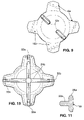
- FIG. 9 is a plan view of the second embodiment chair.
- FIG. 10 is a bottom view of the second embodiment chair
- FIG. 11 is a cross-sectional view taken on the plane designated by line 11 - 11 of FIG. 7 ;
- FIG. 12 is a plan view of the bearing plate of the present invention.
- FIG. 13 is a cross-sectional view of the bearing plate, taken on the plane designated by line 13 - 13 of FIG. 12 ;
- FIG. 14 is a perspective view of the FIG. 12 bearing plate
- FIG. 15 is a perspective view of the first embodiment chair of FIG. 1 , shown supported on the bearing plate of FIG. 12 ;
- FIG. 16 is a cross-sectional elevational view taken on the plane designated by line 16 - 16 of FIG. 15 ;
- FIG. 17 is an elevational view of a third embodiment of the inventive chair, similar to that of FIGS. 1 to 6 , except that it is additionally provided with an integrally formed strap and securing means therefore;
- FIG. 18 is a perspective view of a fourth embodiment of the inventive chair, viewed from toward the top, wherein no ring is provided between the legs of the chair and the table of the chair of a generally X-shaped configuration;
- FIG. 19 is a plan view of the fourth embodiment chair.
- FIG. 20 is a bottom view of the fourth embodiment chair
- FIG. 21 is an elevational view of the fourth embodiment chair.
- FIG. 22 is a perspective view of the fourth embodiment chair, viewed toward the bottom.
- All embodiments of the inventive chair are injection molded from polymeric material.
- a preferred material has been found to be a derivative of recycled polypropylene known as “PRE-TUF” by PrePlastics of Auburn, Calif.
- Other suitable materials are polycarbonate/ABS alloy, polypropylene, polyethylene, polystyrene, glass filled polystyrene, glass filled nylon, and polyvinyl chloride.
- the dimensions of the chair may vary, depending on the thickness of the concrete slab being formed. Typical chair heights range from one and one-quarter inch to ten inches, in one-quarter inch increments. The angle at which the legs diverge from the supporting table of the chair is chosen for optimum strength and stability, with the preferred range being 94° to 104°.
- the chair of this embodiment is shown in FIGS. 1 to 6 and designated in its entirety by the letter C 1 . It comprises a horizontal table 10 of a generally circular configuration having ears 12 extending upwardly from diametrically opposite sides thereof to define a rebar receiving cradle 14 ; legs 16 integrally formed with the table 10 and diverging downwardly and outwardly therefrom; and a ring 18 formed integrally with the legs 16 at a location intermediate the table 10 and distal ends of the legs 16 . As shown, four legs 16 are provided and extend downwardly from the table 10 at equally spaced annular locations around the table. The ears are located so as to be between the legs, thus providing a stable arrangement where two legs are disposed to either side of a rebar received in the cradle between the ears.
- the legs are of a generally T-shaped cross-section and each comprise an outer surface portion 20 and an inwardly extending reinforcing web portion 22 .
- the outer surface portions define as interrupted frusto conical cone diverging downwardly from the table 10 .
- the web portions 22 taper from either end of the legs so as to have an increased depth portion approximately mid-length of the legs (see FIG. 2 ).
- the later construction provides a truss-like reinforcement for the legs which renders them very rigid.
- the web portions of oppositely disposed legs include a central portion 24 integrally formed with and extending beneath the table 10 .
- the merger between the reinforcing web portions 22 and central portion 24 has a relatively large radius, thus adding to the overall rigidity of the chair.
- the central portions 24 meet at the center of the table 10 (see FIG. 4 ) to add even more to this rigidity.
- the ring 18 merges with the outer surface portions 20 of the legs so as to form a smooth outer surface continuing the interrupted conical configuration defined by the outer surface portions.
- the ring is arched so as to provide radius portions 26 which increase the area of merger between the ring and the legs and serve to expand the reinforcement to the legs provided by the ring.
- the ring 18 tapers in thickness from its upper edge 28 to its lower edge 29 (see FIG. 5 ). This configuration ideally suits the chair for injection molding with a core of simple construction which may be readily removed.
- the distal ends of the legs 16 are formed by extensions 30 of the web portions 22 (see FIG. 2 ). These extensions are disposed inwardly on the outer surfaces of the portions 20 and provide a foot including, traction means in the form of serrations 32 , formed on the under-surface of the extensions.
- the serrations 32 extend transversely of the web portions 22 .
- the outer surface portions 20 converge towards the extensions 30 through inclined surfaces 34 proximal to the distal ends of the legs. These inclined surfaces provide space proximal to the distal ends of the legs 16 into which fluid concrete formed around the legs may flow, thus avoiding the creation of voids in the concrete. Such voids are also avoided through the use of rounded radiuses 36 at the merger of the web portions 22 and the extensions 32 .
- the cradle defined between the ears 12 extends transversely across the table 10 so that a rebar R (see FIG. 2 ) supported on the table is disposed between the legs 16 .
- a rebar R see FIG. 2
- two legs are disposed symmetrically to either side of the rebar.
- This embodiment is shown in FIGS. 7 to 11 and designated, in its entirety, by the reference C 2 . It differs from the first embodiment primarily in that it is not provided with a ring, such as the ring 18 , and in that the web portions converge uniformly towards the distal ends of the legs. Parts of the second embodiment corresponding to those of the first embodiment are designated by like numerals, followed by the reference “a”, as follows:
- the web portions 22 a converge uniformly in a generally straight line from the central portion 24 a to the extensions 30 a .
- a shoulder 38 is formed between the inclined surfaces 34 a and the extensions 30 a.
- the second embodiment operates in the same manner as the first embodiment in that the cradle 14 a extends transversely of the table 10 a between a pair of legs 20 a to either side thereof.
- first and second embodiments function in the same way, the first embodiment is especially designed for relatively high chairs where the legs 16 are quite long and the added reinforcement provided by the ring 18 and the truss-like reinforcing of portions 22 greatly enhances the rigidity of the chair structure.
- the second embodiment is a simplified construction ideally suited for use in relatively short chairs.
- the bearing plate shown in FIGS. 12 to 16 is designated in its entirety by the reference B and is for purposes of supporting the chair of the invention against uneven penetration into soft soil. Such plates are also known in the trade as “sand plates.”
- the body of plate B is fabricated of a polymer material similar to that of the chair. It is designed to universally accommodate chairs of different heights and may be used to support any of the embodiments of the chairs herein disclosed.
- a typical plate would measure 41 ⁇ 2 by 41 ⁇ 2 inches and have a thickness of one-quarter inch.
- the plate B is formed with generally triangular lightening holes 40 and a central hole 42 . These holes are intended primarily to conserve material and lighten the weight of the plate. Diagonally extending slots 44 extend radially relative to the central hole 42 for alignment with and complimental receipt of the extensions 30 , 30 a , and 30 b of the chairs. These slots have a transverse dimension slightly less than that of the extensions, so that the opposed side surfaces of the slots, designated 46 , 48 (see FIG. 13 ) snuggly receive and frictionally engage opposite sides of the extensions.
- FIGS. 15 and 16 show the chair C 1 of the first embodiment with the extensions 30 thereof snuggly received within the slots 44 .
- the extensions 30 are disposed intermediate the radially spaced inner and outer extremities of the slots 44 . This demonstrates how a particular bearing plate B may accommodate chairs of different sizes. For smaller chairs, the extensions 30 , 30 a would be closer to the center of the plate.
- the flat planar top surface of the plate B facilitates the formation of concrete around the assembled plate and chair, without creating voids. This contrasts to prior art plates wherein upperwardly extending structure on the plates may create such voids.
- the chair of this embodiment is shown in FIG. 17 . It differs from the first embodiment chair in that it is provided with a strap S and retaining tab T therefor.
- the strap S is integrally formed with the chair C 1 to the outside of an in alignment with one of the ears 12 .
- the tab T is integrally formed with the chair C 1 in alignment with and extending downwardly from the other of the ears 12 .
- the thickness of the strap S is such that the strap is relatively flexible.
- Generally rectangular openings 50 are formed through the strap S at spaced intervals for select engagement over the tab T.
- the phantom line illustration in FIG. 17 illustrates the condition which the strap would assume when engaged over the tab T. As so engaged, the strap would extend over and retain a rebar supported on the cradle of the chair.
- the alignment of the strap S with the ears 12 assures that such engagement is secure.
- the chair of this embodiment is shown in FIGS. 18 to 22 and is designated, in its entirety, by reference C 4 . It differs from the second embodiment primarily in that:
- the table is of a cross-shaped planar configuration
- the fourth embodiment also differs from the second embodiment in that it is provided with additional reinforcing webs 52 integrally formed with the table 10 b and merging with the reinforcing web portions 22 b (see FIG. 20 ).
- the reinforcing webs 52 function to further rigidify the legs 16 b and to provide additional support for the table 10 b.
- the crossed-shaped configuration of the table 10 b also differs from that of the tables 10 and 10 a in that it is not of a planar configuration. Rather, it is of a generally concave configuration at the portion thereof defining the cradle 14 b .
- the ears 12 b are of a concave arcuate configuration which merge with the cradle 14 b , as may best be seen from FIG. 21 .
- the cross-shaped table 10 b has inwardly scalloped edges between the legs 16 b (see FIG. 18 ).
- the scalloped configuration has the advantage that it provides open space between the legs which facilitates extending a tie element beneath the table and over a rebar supported thereon.
Landscapes
- Engineering & Computer Science (AREA)
- Architecture (AREA)
- Civil Engineering (AREA)
- Structural Engineering (AREA)
- Reinforcement Elements For Buildings (AREA)
Abstract
Description
Claims (38)
Priority Applications (2)
| Application Number | Priority Date | Filing Date | Title |
|---|---|---|---|
| US10/810,219 US7451580B2 (en) | 2004-03-26 | 2004-03-26 | Rebar chair and supporting plate |
| US12/290,190 US8028490B2 (en) | 2004-03-26 | 2008-10-28 | Rebar chair |
Applications Claiming Priority (1)
| Application Number | Priority Date | Filing Date | Title |
|---|---|---|---|
| US10/810,219 US7451580B2 (en) | 2004-03-26 | 2004-03-26 | Rebar chair and supporting plate |
Related Child Applications (1)
| Application Number | Title | Priority Date | Filing Date |
|---|---|---|---|
| US12/290,190 Continuation-In-Part US8028490B2 (en) | 2004-03-26 | 2008-10-28 | Rebar chair |
Publications (2)
| Publication Number | Publication Date |
|---|---|
| US20050210816A1 US20050210816A1 (en) | 2005-09-29 |
| US7451580B2 true US7451580B2 (en) | 2008-11-18 |
Family
ID=34988097
Family Applications (1)
| Application Number | Title | Priority Date | Filing Date |
|---|---|---|---|
| US10/810,219 Expired - Lifetime US7451580B2 (en) | 2004-03-26 | 2004-03-26 | Rebar chair and supporting plate |
Country Status (1)
| Country | Link |
|---|---|
| US (1) | US7451580B2 (en) |
Cited By (37)
| Publication number | Priority date | Publication date | Assignee | Title |
|---|---|---|---|---|
| US20080178554A1 (en) * | 2007-01-29 | 2008-07-31 | Mckay Gary Dan | Concrete Reinforcement Support Chair |
| USD594737S1 (en) | 2008-10-28 | 2009-06-23 | Mmi Management Services Lp | Rebar chair |
| US20100132290A1 (en) * | 2006-02-28 | 2010-06-03 | Ropak Corporation | Nestable structural hollow body and related methods |
| USD618988S1 (en) * | 2006-12-11 | 2010-07-06 | Peterson Jr David J | Rebar chair with depth gauge |
| US20110150511A1 (en) * | 2004-07-26 | 2011-06-23 | Seiko Epson Corporation | Image Forming Apparatus, Image Forming Method and Data Control Device |
| US20110214382A1 (en) * | 2010-03-02 | 2011-09-08 | JAB Plastic Products Corporation | Rebar support chair |
| US20110214381A1 (en) * | 2010-03-02 | 2011-09-08 | JAB Plastic Products Corporation | Supporting rebar with interchangeable crowns |
| US8028490B2 (en) | 2004-03-26 | 2011-10-04 | Mmi Products, Inc. | Rebar chair |
| USD650655S1 (en) | 2010-08-18 | 2011-12-20 | Beaver Plastics Ltd. | Rebar chair |
| USD651503S1 (en) * | 2011-01-13 | 2012-01-03 | Dallas Ellis | Armature bracket |
| US20120011799A1 (en) * | 2009-10-28 | 2012-01-19 | Ian Reginald Beaumont | Support element for a reinforcing rod |
| USD672921S1 (en) * | 2011-04-19 | 2012-12-18 | Classic Brands, LLC | Seed allocator for a wild bird feeder |
| USD706608S1 (en) * | 2012-08-22 | 2014-06-10 | Karl Offermann | Rebar chair |
| US8833301B2 (en) | 2012-04-02 | 2014-09-16 | Classic Brands, LLC | Bird feeder with rotating perch |
| US8844238B2 (en) * | 2012-10-26 | 2014-09-30 | Concrete Countertop Solutions, Inc. | Reinforcement support member and kit |
| US8857374B1 (en) | 2011-05-13 | 2014-10-14 | Classic Brands, LLC | Hopper type wild bird feeder |
| USD719817S1 (en) * | 2012-09-21 | 2014-12-23 | Jack Perry | Chair |
| USD721262S1 (en) * | 2013-06-25 | 2015-01-20 | BIP Company, LLC | Concrete reinforcement retaining chair |
| US8978586B1 (en) | 2012-05-23 | 2015-03-17 | Classic Brands, LLC | Wild bird feed dispenser with squirrel-resistant mechanism |
| USD738194S1 (en) * | 2013-10-25 | 2015-09-08 | Concrete Countertop Solutions, Inc. | Reinforcement support member |
| USD791579S1 (en) * | 2015-09-08 | 2017-07-11 | Jack Perry | Chair |
| USD838576S1 (en) | 2018-01-19 | 2019-01-22 | OCM, Inc. | Stackable rebar chair extension |
| US10246878B2 (en) * | 2015-07-08 | 2019-04-02 | Innovativ Plast I Vaest Ab | Stackable wall spacer for supporting reinforcement in concrete constructions |
| US10280623B1 (en) * | 2017-11-03 | 2019-05-07 | Angelo Verelli | Multifunctional rebar support system for reinforcement of concrete structures |
| US10463025B2 (en) | 2010-05-03 | 2019-11-05 | Classic Brands, LLC | Reversible insert for bird feeder |
| USD869935S1 (en) * | 2018-07-24 | 2019-12-17 | Robert Ireland | Stand |
| USD889940S1 (en) * | 2019-04-02 | 2020-07-14 | Inland Concrete Products, Inc. | Support chair for poured concrete reinforcement members |
| USRE48343E1 (en) | 2010-05-03 | 2020-12-08 | Classic Brands, LLC | Hopper type wild bird feeder |
| US20210097213A1 (en) * | 2019-09-26 | 2021-04-01 | Joaquim Caracas | Computer-implemented verification of post-tensioning systems |
| USD920657S1 (en) * | 2018-12-03 | 2021-06-01 | Emily Isooda Tayebi | Modular umbrella stand |
| US20220010544A1 (en) * | 2018-11-15 | 2022-01-13 | Yucheng JIANG | Assembled structure system and applications thereof |
| US20230116868A1 (en) * | 2020-05-18 | 2023-04-13 | ModCribs, LLC | Temporary support stand for a volumetric modular unit |
| USD1018259S1 (en) * | 2022-03-08 | 2024-03-19 | P&P Imports LLC | Pole anchor |
| USD1019351S1 (en) | 2022-08-11 | 2024-03-26 | Inland Concrete Products, Inc. | Support chair for poured concrete reinforcement members |
| USD1027617S1 (en) | 2022-06-22 | 2024-05-21 | Inland Concrete Products, Inc. | Support chair for poured concrete reinforcement members |
| USD1031416S1 (en) | 2022-06-22 | 2024-06-18 | Inland Concrete Products, Inc. | Support chair for poured concrete reinforcement members |
| USD1033211S1 (en) | 2022-08-11 | 2024-07-02 | Inland Concrete Products, Inc. | Support chair for poured concrete reinforcement members |
Families Citing this family (8)
| Publication number | Priority date | Publication date | Assignee | Title |
|---|---|---|---|---|
| US7845136B1 (en) * | 2003-10-20 | 2010-12-07 | Sorkin Felix L | Expansion-resistive construction chair for use with tilt-wall construction |
| USD548056S1 (en) | 2006-04-28 | 2007-08-07 | Eagle Eye Products, Inc. | Rebar stackable chair |
| ES2318979B1 (en) * | 2006-07-25 | 2010-02-05 | Desarrollos Tecnologicos Del Sur, S | FERRALLA SEPARATORS FOR FORGED. |
| US20080028718A1 (en) * | 2006-08-02 | 2008-02-07 | Erickson John A | Stackable rebar support chair |
| CA2692454A1 (en) * | 2007-03-28 | 2008-10-02 | Richard Edward Barry | Device for maintaining ventilation space between heat emitting light fittings or appliances and insulating material |
| US8443567B2 (en) * | 2009-09-21 | 2013-05-21 | David G. Swenson | Spacer for welded wire reinforcement in concrete structures |
| US11439243B2 (en) * | 2019-01-24 | 2022-09-13 | M. Brent Norton | Systems and methods for providing a convertible bench |
| US20210310247A1 (en) * | 2020-04-07 | 2021-10-07 | Felix Sorkin | Bar support and method of making a bar support |
Citations (31)
| Publication number | Priority date | Publication date | Assignee | Title |
|---|---|---|---|---|
| US1672852A (en) | 1927-04-30 | 1928-06-05 | Walter F Bossert | Support for concrete reenforcing members |
| US1809870A (en) | 1927-11-16 | 1931-06-16 | Walter F Bossert | Concrete reenforcement |
| US1936536A (en) | 1932-12-22 | 1933-11-21 | Beulah H Bates | Flooring structure |
| GB575043A (en) | 1944-02-22 | 1946-01-31 | Karl Matsson | Improvements in or relating to reinforced concrete slabs, plates or other concrete bodies, and the manufacture thereof |
| US3693310A (en) * | 1970-11-09 | 1972-09-26 | Pre Stress Concrete | Support for elongated reinforcing members in concrete structures |
| US3830032A (en) * | 1972-09-21 | 1974-08-20 | Prod Corp T | Mesh chair for concrete reinforcement |
| US4060954A (en) | 1972-11-03 | 1977-12-06 | Liuzza James J | Bar chair for reinforcing rods |
| US4080770A (en) | 1974-08-06 | 1978-03-28 | Sandor Vigh | High chair spacer |
| US4483119A (en) | 1981-04-01 | 1984-11-20 | Ernest Hernandez | Bar support for use with reinforced concrete |
| FR2549870A1 (en) | 1983-07-27 | 1985-02-01 | Materiaux Etancheite Entrepris | Studs for paving stones |
| US4655023A (en) | 1985-01-23 | 1987-04-07 | Yung Fernand P | Spacer for construction use |
| US4682461A (en) | 1986-03-31 | 1987-07-28 | Winston C. Sizemore | Support for reinforcing bar |
| US4756641A (en) * | 1987-09-02 | 1988-07-12 | George Hartzheim | Sand plate and concrete reinforcement support |
| US4835933A (en) * | 1988-02-11 | 1989-06-06 | Yung Fernand P | Rebar spacer assembly |
| WO1990001600A1 (en) * | 1988-08-15 | 1990-02-22 | Dkc Manufacturing, Inc. | Construction spacer and method of use |
| US5107654A (en) * | 1988-10-07 | 1992-04-28 | Nicola Leonardis | Foundation reinforcement chairs |
| USD334133S (en) | 1991-12-26 | 1993-03-23 | George Hartzheim | Support for metal reinforcements in poured concrete |
| US5555693A (en) * | 1995-01-12 | 1996-09-17 | Sorkin; Felix L. | Chair for use in construction |
| USD388312S (en) | 1996-05-28 | 1997-12-30 | Sorkin Felix L | Construction chair |
| US5729949A (en) | 1996-09-09 | 1998-03-24 | Hartzheim; G. Douglas | Slab on grade chair |
| USD394200S (en) | 1996-05-07 | 1998-05-12 | Hartzheim G Douglas | Slab on grade chair |
| US5791095A (en) | 1995-01-12 | 1998-08-11 | Sorkin; Felix L. | Chair for use in construction |
| USD421709S (en) | 1998-10-02 | 2000-03-21 | Aztec Concrete Accessories, Inc. | Tower chair |
| USD428501S (en) | 1998-10-02 | 2000-07-18 | Aztec Concrete Accessories, Inc. | Chair |
| US6089522A (en) * | 1998-10-02 | 2000-07-18 | Aztec Concrete Accessories, Inc. | Method and apparatus for supporting reinforcement members |
| USD443197S1 (en) | 1999-10-19 | 2001-06-05 | Gopa Enterprises | Holder for concrete reinforcing elements |
| USD444244S1 (en) | 2000-06-01 | 2001-06-26 | Mcpherson John W. | Rebar chair |
| US6276108B1 (en) | 1999-10-19 | 2001-08-21 | Gopa Enterprises | Device for supporting and connecting reinforcing elements for concrete structures |
| US6354054B1 (en) | 1998-11-06 | 2002-03-12 | Angelo Verelli | Rebar support system |
| USD454776S1 (en) | 1999-10-19 | 2002-03-26 | Gopa Enterprises | Holder for concrete reinforcing elements |
| US20030000170A1 (en) | 2001-06-29 | 2003-01-02 | Sorkin Felix L. | Concrete reinforcing bar support |
-
2004
- 2004-03-26 US US10/810,219 patent/US7451580B2/en not_active Expired - Lifetime
Patent Citations (31)
| Publication number | Priority date | Publication date | Assignee | Title |
|---|---|---|---|---|
| US1672852A (en) | 1927-04-30 | 1928-06-05 | Walter F Bossert | Support for concrete reenforcing members |
| US1809870A (en) | 1927-11-16 | 1931-06-16 | Walter F Bossert | Concrete reenforcement |
| US1936536A (en) | 1932-12-22 | 1933-11-21 | Beulah H Bates | Flooring structure |
| GB575043A (en) | 1944-02-22 | 1946-01-31 | Karl Matsson | Improvements in or relating to reinforced concrete slabs, plates or other concrete bodies, and the manufacture thereof |
| US3693310A (en) * | 1970-11-09 | 1972-09-26 | Pre Stress Concrete | Support for elongated reinforcing members in concrete structures |
| US3830032A (en) * | 1972-09-21 | 1974-08-20 | Prod Corp T | Mesh chair for concrete reinforcement |
| US4060954A (en) | 1972-11-03 | 1977-12-06 | Liuzza James J | Bar chair for reinforcing rods |
| US4080770A (en) | 1974-08-06 | 1978-03-28 | Sandor Vigh | High chair spacer |
| US4483119A (en) | 1981-04-01 | 1984-11-20 | Ernest Hernandez | Bar support for use with reinforced concrete |
| FR2549870A1 (en) | 1983-07-27 | 1985-02-01 | Materiaux Etancheite Entrepris | Studs for paving stones |
| US4655023A (en) | 1985-01-23 | 1987-04-07 | Yung Fernand P | Spacer for construction use |
| US4682461A (en) | 1986-03-31 | 1987-07-28 | Winston C. Sizemore | Support for reinforcing bar |
| US4756641A (en) * | 1987-09-02 | 1988-07-12 | George Hartzheim | Sand plate and concrete reinforcement support |
| US4835933A (en) * | 1988-02-11 | 1989-06-06 | Yung Fernand P | Rebar spacer assembly |
| WO1990001600A1 (en) * | 1988-08-15 | 1990-02-22 | Dkc Manufacturing, Inc. | Construction spacer and method of use |
| US5107654A (en) * | 1988-10-07 | 1992-04-28 | Nicola Leonardis | Foundation reinforcement chairs |
| USD334133S (en) | 1991-12-26 | 1993-03-23 | George Hartzheim | Support for metal reinforcements in poured concrete |
| US5555693A (en) * | 1995-01-12 | 1996-09-17 | Sorkin; Felix L. | Chair for use in construction |
| US5791095A (en) | 1995-01-12 | 1998-08-11 | Sorkin; Felix L. | Chair for use in construction |
| USD394200S (en) | 1996-05-07 | 1998-05-12 | Hartzheim G Douglas | Slab on grade chair |
| USD388312S (en) | 1996-05-28 | 1997-12-30 | Sorkin Felix L | Construction chair |
| US5729949A (en) | 1996-09-09 | 1998-03-24 | Hartzheim; G. Douglas | Slab on grade chair |
| USD428501S (en) | 1998-10-02 | 2000-07-18 | Aztec Concrete Accessories, Inc. | Chair |
| USD421709S (en) | 1998-10-02 | 2000-03-21 | Aztec Concrete Accessories, Inc. | Tower chair |
| US6089522A (en) * | 1998-10-02 | 2000-07-18 | Aztec Concrete Accessories, Inc. | Method and apparatus for supporting reinforcement members |
| US6354054B1 (en) | 1998-11-06 | 2002-03-12 | Angelo Verelli | Rebar support system |
| USD443197S1 (en) | 1999-10-19 | 2001-06-05 | Gopa Enterprises | Holder for concrete reinforcing elements |
| US6276108B1 (en) | 1999-10-19 | 2001-08-21 | Gopa Enterprises | Device for supporting and connecting reinforcing elements for concrete structures |
| USD454776S1 (en) | 1999-10-19 | 2002-03-26 | Gopa Enterprises | Holder for concrete reinforcing elements |
| USD444244S1 (en) | 2000-06-01 | 2001-06-26 | Mcpherson John W. | Rebar chair |
| US20030000170A1 (en) | 2001-06-29 | 2003-01-02 | Sorkin Felix L. | Concrete reinforcing bar support |
Non-Patent Citations (3)
| Title |
|---|
| AZTEC Promotional Brochure for Plastic Rebar Spacer (1994). |
| Meadow Steel Products Plastic Accessories Catalog (1991). |
| Meadow Steel Products Pricing Brochure for Reinforcing Bar Supports (Feb. 1, 1994). |
Cited By (45)
| Publication number | Priority date | Publication date | Assignee | Title |
|---|---|---|---|---|
| US8028490B2 (en) | 2004-03-26 | 2011-10-04 | Mmi Products, Inc. | Rebar chair |
| US20110150511A1 (en) * | 2004-07-26 | 2011-06-23 | Seiko Epson Corporation | Image Forming Apparatus, Image Forming Method and Data Control Device |
| US20100132290A1 (en) * | 2006-02-28 | 2010-06-03 | Ropak Corporation | Nestable structural hollow body and related methods |
| US8322112B2 (en) * | 2006-02-28 | 2012-12-04 | Ropak Corporation | Nestable structural hollow body and related methods |
| USD618988S1 (en) * | 2006-12-11 | 2010-07-06 | Peterson Jr David J | Rebar chair with depth gauge |
| US20080178554A1 (en) * | 2007-01-29 | 2008-07-31 | Mckay Gary Dan | Concrete Reinforcement Support Chair |
| US7870702B2 (en) * | 2007-01-29 | 2011-01-18 | Mckay Gary Dan | Concrete reinforcement support chair |
| USD594737S1 (en) | 2008-10-28 | 2009-06-23 | Mmi Management Services Lp | Rebar chair |
| US20120011799A1 (en) * | 2009-10-28 | 2012-01-19 | Ian Reginald Beaumont | Support element for a reinforcing rod |
| US20110214382A1 (en) * | 2010-03-02 | 2011-09-08 | JAB Plastic Products Corporation | Rebar support chair |
| US20110214381A1 (en) * | 2010-03-02 | 2011-09-08 | JAB Plastic Products Corporation | Supporting rebar with interchangeable crowns |
| USRE48343E1 (en) | 2010-05-03 | 2020-12-08 | Classic Brands, LLC | Hopper type wild bird feeder |
| US10463025B2 (en) | 2010-05-03 | 2019-11-05 | Classic Brands, LLC | Reversible insert for bird feeder |
| USD650655S1 (en) | 2010-08-18 | 2011-12-20 | Beaver Plastics Ltd. | Rebar chair |
| USD651503S1 (en) * | 2011-01-13 | 2012-01-03 | Dallas Ellis | Armature bracket |
| USD672921S1 (en) * | 2011-04-19 | 2012-12-18 | Classic Brands, LLC | Seed allocator for a wild bird feeder |
| US8857374B1 (en) | 2011-05-13 | 2014-10-14 | Classic Brands, LLC | Hopper type wild bird feeder |
| US8833301B2 (en) | 2012-04-02 | 2014-09-16 | Classic Brands, LLC | Bird feeder with rotating perch |
| US8833302B2 (en) | 2012-04-02 | 2014-09-16 | Classic Brands, LLC | Bird feeder with rotating perch |
| US8978586B1 (en) | 2012-05-23 | 2015-03-17 | Classic Brands, LLC | Wild bird feed dispenser with squirrel-resistant mechanism |
| USD706608S1 (en) * | 2012-08-22 | 2014-06-10 | Karl Offermann | Rebar chair |
| USD738195S1 (en) * | 2012-09-21 | 2015-09-08 | Jack Perry | Chair |
| USD719817S1 (en) * | 2012-09-21 | 2014-12-23 | Jack Perry | Chair |
| US8844238B2 (en) * | 2012-10-26 | 2014-09-30 | Concrete Countertop Solutions, Inc. | Reinforcement support member and kit |
| USD721262S1 (en) * | 2013-06-25 | 2015-01-20 | BIP Company, LLC | Concrete reinforcement retaining chair |
| USD738194S1 (en) * | 2013-10-25 | 2015-09-08 | Concrete Countertop Solutions, Inc. | Reinforcement support member |
| USD751369S1 (en) | 2013-10-25 | 2016-03-15 | Concrete Countertop Solutions, Inc. | Reinforcement support member |
| US10246878B2 (en) * | 2015-07-08 | 2019-04-02 | Innovativ Plast I Vaest Ab | Stackable wall spacer for supporting reinforcement in concrete constructions |
| USD791579S1 (en) * | 2015-09-08 | 2017-07-11 | Jack Perry | Chair |
| US10280623B1 (en) * | 2017-11-03 | 2019-05-07 | Angelo Verelli | Multifunctional rebar support system for reinforcement of concrete structures |
| USD838576S1 (en) | 2018-01-19 | 2019-01-22 | OCM, Inc. | Stackable rebar chair extension |
| USD869935S1 (en) * | 2018-07-24 | 2019-12-17 | Robert Ireland | Stand |
| US20220010544A1 (en) * | 2018-11-15 | 2022-01-13 | Yucheng JIANG | Assembled structure system and applications thereof |
| US11634902B2 (en) * | 2018-11-15 | 2023-04-25 | Yucheng JIANG | Assembled structure system and applications thereof |
| USD920657S1 (en) * | 2018-12-03 | 2021-06-01 | Emily Isooda Tayebi | Modular umbrella stand |
| USD889940S1 (en) * | 2019-04-02 | 2020-07-14 | Inland Concrete Products, Inc. | Support chair for poured concrete reinforcement members |
| US12475272B2 (en) * | 2019-09-26 | 2025-11-18 | Impacto Protensão Ltd | Computer-implemented verification of post-tensioning systems |
| US20210097213A1 (en) * | 2019-09-26 | 2021-04-01 | Joaquim Caracas | Computer-implemented verification of post-tensioning systems |
| US20230116868A1 (en) * | 2020-05-18 | 2023-04-13 | ModCribs, LLC | Temporary support stand for a volumetric modular unit |
| US12234943B2 (en) * | 2020-05-18 | 2025-02-25 | ModCribs, LLC | Temporary support stand for a volumetric modular unit |
| USD1018259S1 (en) * | 2022-03-08 | 2024-03-19 | P&P Imports LLC | Pole anchor |
| USD1027617S1 (en) | 2022-06-22 | 2024-05-21 | Inland Concrete Products, Inc. | Support chair for poured concrete reinforcement members |
| USD1031416S1 (en) | 2022-06-22 | 2024-06-18 | Inland Concrete Products, Inc. | Support chair for poured concrete reinforcement members |
| USD1019351S1 (en) | 2022-08-11 | 2024-03-26 | Inland Concrete Products, Inc. | Support chair for poured concrete reinforcement members |
| USD1033211S1 (en) | 2022-08-11 | 2024-07-02 | Inland Concrete Products, Inc. | Support chair for poured concrete reinforcement members |
Also Published As
| Publication number | Publication date |
|---|---|
| US20050210816A1 (en) | 2005-09-29 |
Similar Documents
| Publication | Publication Date | Title |
|---|---|---|
| US7451580B2 (en) | Rebar chair and supporting plate | |
| US8028490B2 (en) | Rebar chair | |
| US6354054B1 (en) | Rebar support system | |
| US4682461A (en) | Support for reinforcing bar | |
| US4756641A (en) | Sand plate and concrete reinforcement support | |
| US5729949A (en) | Slab on grade chair | |
| US7028443B2 (en) | Wire mesh chair | |
| MXPA04006317A (en) | Rebar support chair. | |
| US6948291B2 (en) | Plastic slab bolster upper | |
| US6089522A (en) | Method and apparatus for supporting reinforcement members | |
| US5271203A (en) | Support form for a settable material | |
| WO2012054959A1 (en) | Spacer for supporting a reinforcing bar | |
| US20090044481A1 (en) | Rebar, beam and mesh highchair | |
| US20070193189A1 (en) | Rebar Support Chair | |
| US20040194414A1 (en) | Chair for supporting wire mesh | |
| US6732484B1 (en) | Chair support for metal reinforcements | |
| US10280623B1 (en) | Multifunctional rebar support system for reinforcement of concrete structures | |
| CA2681416C (en) | Rebar chair | |
| US20190390460A1 (en) | Chair for supporting reinforcing bars and method of using the same | |
| AU2007214291B2 (en) | Rebar support chair | |
| WO2013074987A1 (en) | Multifunction stackable chair for concrete reinforcing elements | |
| US11939769B1 (en) | Support for reinforcing members in concrete footing | |
| CA2252200C (en) | Rebar support system | |
| US11927013B1 (en) | Support for concrete reinforcing members | |
| AU2012100930A4 (en) | Spacer for supporting a reinforcing bar |
Legal Events
| Date | Code | Title | Description |
|---|---|---|---|
| AS | Assignment |
Owner name: MMI MANAGEMENT SERVICIES LP, TEXAS Free format text: ASSIGNMENT OF ASSIGNORS INTEREST;ASSIGNORS:KELLY, DAVID L.;MILLER, STEPHEN L.;MILLER, RICHARD L.;REEL/FRAME:015159/0406 Effective date: 20040317 |
|
| STCF | Information on status: patent grant |
Free format text: PATENTED CASE |
|
| AS | Assignment |
Owner name: MMI PRODUCTS, INC.,GEORGIA Free format text: MERGER;ASSIGNOR:MMI MANAGEMENT SERVICES LP;REEL/FRAME:024576/0493 Effective date: 20091231 Owner name: MMI PRODUCTS, INC., GEORGIA Free format text: MERGER;ASSIGNOR:MMI MANAGEMENT SERVICES LP;REEL/FRAME:024576/0493 Effective date: 20091231 |
|
| AS | Assignment |
Owner name: MEADOW BURKE, LLC, FLORIDA Free format text: ASSIGNMENT OF ASSIGNORS INTEREST;ASSIGNOR:MMI PRODUCTS, INC.;REEL/FRAME:027457/0537 Effective date: 20101230 |
|
| FPAY | Fee payment |
Year of fee payment: 4 |
|
| FPAY | Fee payment |
Year of fee payment: 8 |
|
| MAFP | Maintenance fee payment |
Free format text: PAYMENT OF MAINTENANCE FEE, 12TH YEAR, LARGE ENTITY (ORIGINAL EVENT CODE: M1553); ENTITY STATUS OF PATENT OWNER: LARGE ENTITY Year of fee payment: 12 |