US7447221B2 - Communication apparatus - Google Patents
Communication apparatus Download PDFInfo
- Publication number
- US7447221B2 US7447221B2 US11/105,442 US10544205A US7447221B2 US 7447221 B2 US7447221 B2 US 7447221B2 US 10544205 A US10544205 A US 10544205A US 7447221 B2 US7447221 B2 US 7447221B2
- Authority
- US
- United States
- Prior art keywords
- packet
- communication
- address
- information
- encapsulation
- Prior art date
- Legal status (The legal status is an assumption and is not a legal conclusion. Google has not performed a legal analysis and makes no representation as to the accuracy of the status listed.)
- Expired - Fee Related, expires
Links
Images


Classifications
-
- H—ELECTRICITY
- H04—ELECTRIC COMMUNICATION TECHNIQUE
- H04L—TRANSMISSION OF DIGITAL INFORMATION, e.g. TELEGRAPHIC COMMUNICATION
- H04L45/00—Routing or path finding of packets in data switching networks
- H04L45/52—Multiprotocol routers
-
- H—ELECTRICITY
- H04—ELECTRIC COMMUNICATION TECHNIQUE
- H04L—TRANSMISSION OF DIGITAL INFORMATION, e.g. TELEGRAPHIC COMMUNICATION
- H04L12/00—Data switching networks
- H04L12/28—Data switching networks characterised by path configuration, e.g. LAN [Local Area Networks] or WAN [Wide Area Networks]
- H04L12/46—Interconnection of networks
- H04L12/4633—Interconnection of networks using encapsulation techniques, e.g. tunneling
-
- H—ELECTRICITY
- H04—ELECTRIC COMMUNICATION TECHNIQUE
- H04L—TRANSMISSION OF DIGITAL INFORMATION, e.g. TELEGRAPHIC COMMUNICATION
- H04L45/00—Routing or path finding of packets in data switching networks
- H04L45/02—Topology update or discovery
- H04L45/04—Interdomain routing, e.g. hierarchical routing
-
- H—ELECTRICITY
- H04—ELECTRIC COMMUNICATION TECHNIQUE
- H04L—TRANSMISSION OF DIGITAL INFORMATION, e.g. TELEGRAPHIC COMMUNICATION
- H04L69/00—Network arrangements, protocols or services independent of the application payload and not provided for in the other groups of this subclass
- H04L69/16—Implementation or adaptation of Internet protocol [IP], of transmission control protocol [TCP] or of user datagram protocol [UDP]
- H04L69/167—Adaptation for transition between two IP versions, e.g. between IPv4 and IPv6
-
- H—ELECTRICITY
- H04—ELECTRIC COMMUNICATION TECHNIQUE
- H04L—TRANSMISSION OF DIGITAL INFORMATION, e.g. TELEGRAPHIC COMMUNICATION
- H04L69/00—Network arrangements, protocols or services independent of the application payload and not provided for in the other groups of this subclass
- H04L69/16—Implementation or adaptation of Internet protocol [IP], of transmission control protocol [TCP] or of user datagram protocol [UDP]
Definitions
- the present invention relates to a communication apparatus enabling an Intranet connection in a network where different communication protocols mixedly exist.
- IPv4 Internet Protocol version 4
- IPv6 Internet Protocol version 6
- IPv4 and IPv6 mixedly exist on an IP network.
- IPv6 There are various shifting technologies enabling the IPv6 communication on the conventional IPv4 network in the case of such shifting to IPv6.
- One of those technologies is a tunnel technology, in which an IPv6 packet is encapsulated by an IPv4 header, communication is made by using the IPv4 header in an IPv4 network, and on a network or a terminal, which is capable of the IPv6 communication, the IPv4 header used for the encapsulation is detached to return (decapsulate) the encapsulated packet to the IPv6 packet.
- IPv6 terminal In a 6to4 tunnel, into an IPv6 address of an IPv6 header in an IPv6 packet sent out from a terminal installed with IPv6, which is a transmission source (hereinafter, referred to as “IPv6 terminal”), an IPv4 global address used when the IPv6 packet is encapsulated by IPv4 is embedded.
- the IPv6 packet passes through the IPv4 network, a terminal and a relay apparatus, which are located on an interface between IPv4 and IPv6, take out the IPv4 global address from the IPv6 address. Then, based on the taken-out IPv4 global address, the IPv4 header is automatically created, and communications with the IPv6 packet are thus made possible in the IPv4 network.
- the 6to4 tunnel is one of automatic tunnel technologies.
- the IPv6 communication is performed by using an IPv6 address of a format in which higher-order 16 bits of the IPv6 address are a fixed value which is 2002 in the hexadecimal numbering system and the IPv4 global address is embedded into 32 bits following this fixed value.
- IPv4 header for encapsulation can be automatically created from the IPv4 global address embedded in such a way.
- this embedded IPv4 address must be a global address (described in Chapter 2 of RFC3056 (Non-Patent document 1) which defines the 6to4 tunnel).
- IPv4 private addresses are addresses having prefixes like 10/8, 172.16/12 and 192.168/16, and in any organization, these addresses can be freely used. Therefore, a case normally occurs, where terminals having the same private address exist in plural different organizations.
- IPv4 public network such as the Internet
- a private address cannot be used, and a global address must be used. This is because, when an arbitrary private address is used on the Internet, an address of a terminal overlaps the others, and the terminal cannot be identified.
- the tunnel of the 6to4 format is constructed on the IPv4 public network, and accordingly, the private address has not been usable for the IPv4 address also in the case of using the tunnel of the 6to4 format.
- Patent document 1 discloses a technology for encapsulating, by a 6to4 tunneling encapsulator, a communication between IPv6 domains separated by IPv4 domains.
- Patent document 2 discloses a technology, in which nodes which support incompatible network layer protocols, such as IPv4 and IPv6, determine a protocol set and perform automatic encapsulation therefor.
- IPv4 and IPv6 incompatible network layer protocols
- Patent document 3 discloses a technology for directly interconnecting the private networks through the tunneling by using private IP addresses.
- the present invention has been made in order to solve such a problem. It is an object of the present invention to provide a communication apparatus enabling the use of the private address in the network where the different communication protocols mixedly exist.
- the present invention provides a communication apparatus to be used between a first communication group including one or two or more communication terminals that perform communications by a first type of communication protocol and a second communication group including one or two or more communication terminals that perform communications by a second type of communication protocol capable of embedding address information for use in the first communication group, characterized by including: a first storage unit, in which a destination address to the first communication group or the second communication group, and tunnel identification information for identifying attribute information of a route specified by address information for use in the first communication group when a packet transmitted from the second communication group via the first communication group to another second communication group is encapsulated by the address information for use in the first group and passed through the first communication group, are registered; a destination retrieval unit which makes retrieval as to whether or not a destination address extracted from the received packet is registered in the first storage unit; a second storage unit, in which communication enable/disable information indicating whether or not the route on the first communication group, the route being designated by using the tunnel identification information,
- the communication apparatus to be used between the first communication group including one or two or more communication terminals which perform communications by the first type of communication protocol and the second communication group including one or two or more communication terminals which perform communications by the second type of communication protocol capable of embedding address information for use in the first communication group in the case of transmitting the packet via the first communication group, whether or not the encapsulation including extracting the address information for use in the first communication group from the destination address is to be performed can be determined under control in accordance with the communication enable/disable information in the second storage unit.
- the apparatus is characterized by further including: a decapsulation information storage unit in which information for identifying a packet as an object of decapsulation which restores the encapsulated packet to an original form thereof is registered; and a decapsulation processing unit which decapsulates the received packet in accordance with the information in the decapsulation information storage unit.
- the received packet is decapsulated in accordance with the information in the decapsulation information storage unit, and accordingly, the packet as the object of the decapsulation can be determined efficiently.
- the apparatus is characterized by further including: a discarded information storage unit in which information indicating whether or not the received packet is a packet to be discarded is registered; and a packet discard-unit which discards the received packet in accordance with the information in the discarded information storage unit.
- the received packet is discarded in accordance with the information in the discarded information storage unit, and accordingly, a desired packet can be discarded.
- the apparatus according to the present invention is characterized in that the first storage unit further includes encapsulation information indicating whether or not the encapsulation is to be performed by IPv4 or IPv6, and the encapsulation processing unit encapsulates the packet by IPv4 or IPv6 in accordance with the encapsulation information.
- desired encapsulation processing can be executed for the received packet with reference to the encapsulation information indicating whether or not the encapsulation is to be performed by IPv4 or IPv6 for a predetermined destination address.
- the apparatus according to the present invention is characterized in that the second storage unit further includes packet conversion information indicating whether or not a packet of a 6to4 format is to be encapsulated, and the encapsulation processing unit encapsulates the packet of the 6to4 format in accordance with the packet conversion information.
- the received packet is converted into the packet of the 6to4 format in accordance with the packet conversion information indicating whether or not the packet of the 6to4 format is to be encapsulated. Accordingly, 6to4 encapsulation processing can be executed for a packet to be transmitted to a predetermined destination address.
- the apparatus according to the present invention is characterized in that the encapsulation processing unit executes the discard of the packet or the encapsulation processing for the packet in accordance with the communication enable/disable information.
- the discard of the packet or the encapsulation processing for the packet is executed in accordance with the communication enable/disable information. Accordingly, the discard of the packet or the encapsulation processing for the packet can be executed on a tunnel basis.
- the apparatus according to the present invention is characterized in that the encapsulation processing unit is capable of referring to plural pieces of tunnel identification information registered in a second table, and the encapsulation processing unit refers to, for each tunnel, information indicating whether or not to execute each of a first method permitting only a communication in which the destination address is the global address and a second method permitting only a communication in which the destination address is the private address.
- the information indicating whether or not to execute each of the first method permitting only the communication in which the destination address is the global address and the second method permitting only the communication in which the destination address is the private address is referred to on a tunnel basis. Accordingly, desired packet processing can be executed for each type of the destination address.
- the apparatus according to the present invention is characterized in that, when a tunnel packet in which the destination address is the global address is received with respect to a tunnel interface in which only the second method is selected, the encapsulation processing unit discards the tunnel packet without performing the communication.
- the communication apparatus of the present invention only the tunnel packet in which the destination address is the global address is discarded. Accordingly, the packet with the global address can be prevented from being transmitted to a network in which the private address is used.
- the apparatus according to the present invention is characterized in that, when a packet having an IPv6 address in which an IPv4 global address for use in a first network is embedded as the destination address is encapsulated into an IPv4 packet and transmitted to the tunnel interface in which only the second method is selected, the encapsulation processing unit discards the packet having the IPv6 packet without setting the packet as an object to be transmitted.
- the tunnel packet when the packet having the IPv6 address in which the IPv4 global address is embedded is converted into the tunnel packet of the 6to4 format and transmitted, the tunnel packet is discarded without being set as the object to be transmitted. Accordingly, the packet with the global address can be prevented from being transmitted to the network in which only the private address is used.
- the apparatus of the present invention is characterized in that, when the packet in which the destination address is encapsulated by the IPv4 global address is received with respect to a tunnel interface in which only the first method is selected, or when the packet in which the destination address is the IPv6 address having the IPv4 global address embedded thereinto is encapsulated into the IPv4 packet and transmitted to the tunnel interface, the encapsulation processing unit transmits/receives the encapsulated packet without discarding the encapsulated packet.
- the tunnel packet of the 6to4 format, in which the destination address is the IPv4 global address is received, or when the packet, in which the destination address is the IPv6 address having the IPv4 global address embedded thereinto is converted into the tunnel packet of the 6to4 format and transmitted, the tunnel packet is transmitted/received without being discarded. Accordingly, the packet with the global address can be transmitted/received even in a network where the private address and the global address mixedly exist.
- the apparatus according to the present invention is characterized in that, when a setting of executing the first method or the second method is made, the encapsulation processing unit refers to information indicating whether or not to enable the setting when the packet is transmitted or when the packet is received.
- the communication apparatus of the present invention when the setting of executing the first method or the second method is made, the information indicating whether or not to enable the setting when the packet is transmitted or when the packet is received is referred to. Accordingly, the transmission/receipt of the packet can be controlled on a tunnel basis.
- FIG. 1 is a view showing a configuration of a network in which a tunnel is provided in an in-house communication.
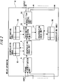
- FIG. 2 is a block diagram explaining a relay apparatus of the present invention.
- FIG. 3 is a view showing a configuration example of a decapsulation table.
- FIG. 4 is a view showing a configuration example of a destination table.
- FIG. 5 is a view showing a configuration example of an encapsulation table.
- FIG. 6 is a flowchart showing operations of a decapsulation check unit.
- FIG. 7 is a flowchart showing operations of a destination retrieval unit.
- FIG. 8 is a flowchart showing operations of an encapsulation check unit.
- FIG. 9 is a flowchart showing operations of the encapsulation check unit.
- FIG. 10 is a view showing a configuration example of a network using IPv6 addresses having IPv4 private addresses embedded thereinto in a case of providing tunnels of a 6to4 format.
- the computer-readable recording medium means a recording medium capable of accumulating data and information regarding the program by means of an electric, magnetic, optical, mechanical or chemical function and reading the information from the computer.
- recording media for example, there are a flexible disk, a magneto-optical disc, a CD-ROM, a CD-R/W, a DVD, a DAT, an 8-mm tape, a memory card, and the like.
- recording media fixed to the computer there are a hard disk, a ROM (read only memory), and the like.
- FIG. 1 is a view showing a configuration example of a network in which a tunnel is constructed in an in-house communication.
- An in-house communication system is composed of an IPv4 in-house network 2 , terminals (hereinafter, referred to as “IPv6 terminals”) which are connected to the IPv4 in-house network 2 and installed with IPv6 creating IPv6 packets, and routers A to C as relay apparatuses.
- IPv6 terminals terminals which are connected to the IPv4 in-house network 2 and installed with IPv6 creating IPv6 packets
- routers A to C as relay apparatuses.
- each of the IPv6 terminals A and B may be a communication group including two or more communication terminals in the present invention.
- the IPv4 in-house network 2 may be a communication group including one or two or more communication terminals.
- the communication group includes terminals (hereinafter, referred to as “IPv4 terminals”) installed with IPv4 creating IPv4 packets.
- IPv4 terminals installed with IPv4 creating IPv4 packets.
- the communication group includes the IPv4 terminal besides the IPv6 terminal in some cases.
- the router A and the router B are illustrated independently of the IPv6 terminals, the IPv6 terminals may be composed such that a function of each router (relay apparatus), which will be described from now on, serves as a part of a function in the IPv6 terminal.
- IPv4 private addresses can be assigned in a single organization without overlapping each other.
- an embedded destination IPv4 address is a private address (10. 11. 12. 13) as shown in FIG. 1 will be described.
- the destination IPv4 private address is embedded.
- the router A which has received the IPv6 packet from the IPv6 terminal A extracts the destination IPv4 private address from the IPv6 packet, encapsulates the IPv6 packet by an IPv4 header (IPv4), and transmits an IPv4 capsule to the router B through the IPv4 in-house network 2 . Then, the router B detaches the IPv4 header of the received packet (IPv4 capsule) (decapsulation), and transmits the IPv6 packet to the IPv6 terminal B.
- IPv4 header IPv4
- the IPv6 terminal A transmits a packet to the router C
- the IPv6 terminal A creates an IPv4 capsule encapsulated by a private address.
- the router C decapsulates the received IPv4 capsule.
- the IPv4 address is discarded without being transmitted to a public network. In such a way, it becomes possible to use the private address for the IPv4 address also in the case of using the tunnel of the 6to4 format. Specific configurations and operations will be described later.
- FIG. 2 is a diagram showing an example of an internal configuration of a relay apparatus 4 .
- the relay apparatus 4 is shown as an example of an internal configuration of each of the routers A to C of FIG. 1 shows an internal configuration for encapsulating and decapsulating the packets. Further, it is possible to realize the configuration of the relay apparatus 4 by each of a communication terminal, a server, and an apparatus on a network where the tunnel of the 6to4 format can be provided.
- the relay apparatus 4 is composed of (1) a frame identification unit 6 which identifies a received packet of IP or the like, (2) a decapsulation check unit 8 which determines whether the packet is an object to be decapsulated, (3) a destination retrieval unit 10 which determines an output destination of the packet based on a destination address, (4) an encapsulation check unit 12 which encapsulates the packet determined as the object to be encapsulated by the destination retrieval unit 10 , and (5) a QoS/Filter control unit 14 which performs QoS control and filtering processing for the packet.
- a decapsulation table 16 , a destination table 18 and an encapsulation table 20 are used in the decapsulation check unit 8 , the destination retrieval unit 10 and the encapsulation check unit 12 , respectively.
- a setting of each table is executed by a computer connected to the relay apparatus 4 , an operation unit (not shown) provided in the relay apparatus 4 , and the like.
- the relay apparatus 4 processes the packet in accordance with a setting value of each table thus set.
- the decapsulation check unit 8 determines whether or not to decapsulate the received packet such as (i) a packet transmitted through the 6to4 tunnel and (ii) a packet transmitted from an IPv4 terminal belonging to the IPv4 in-house network 2 without passing through the 6to4 tunnel.
- the decapsulation check unit 8 is a processing unit which functions in the router B which receives the packet from the IPv6 terminal A in FIG. 1 .
- the encapsulation check unit 12 determines whether or not to encapsulate the received packet such as (i) a packet to be transmitted to the 6to4 tunnel, (ii) the packet received from the 6to4 tunnel and (iii) a packet transmitted from an IPv4 terminal or an IPv6 terminal, which belongs to the IPv4 in-house network 2 , without passing through the 6to4 tunnel.
- the encapsulation check unit 12 is a processing unit which functions in the router A or the router C, which receives the packet from the IPv6 terminal A in FIG. 1 .
- the frame identification unit 6 identifies input packet (received packet), and performs extraction of information such as an address and checking of a header error and the like. This is a function of the conventional relay apparatus.
- the decapsulation check unit 8 is a block which determines whether or not the received packet is the object to be decapsulated. When it is determined by the frame identification unit 6 that the received packet is encapsulated, the decapsulation check unit 8 extracts an IP address from an external IP header of the encapsulated packet (packet in which the external IP header and an internal IP header exist). Then, the decapsulation check unit 8 searches the decapsulation table by using the extracted IP address as a search key.
- IP address extracted by the decapsulation check unit 8 is an IP address (IP DA) and a transmission source IP address (IP SA), which are shown in FIG. 3 .
- IP DA IP address
- IP SA transmission source IP address
- the extracted IP address is an IPv4 address included in the external IP header of the received packet.
- IP addresses shown in FIG. 3 and FIG. 4 are network addresses or host addresses.
- the decapsulation table 16 (corresponding to “discarded information storage unit” of the present invention) is a table which stores information for determining whether or not the packet is the object to be decapsulated.
- FIG. 3 shows an example of details of contents of the decapsulation table 16 .
- a discard flag is acquired by using an external header IP address (transmission source address/destination address) as a search key. If the discard flag is “1”, the packet concerned is discarded. If the discard flag is “0”, the packet is subjected to the next processing without being discarded. Further, only any of the transmission source addresses and the destination addresses may be set in the decapsulation table 16 .
- the packet When the received packet is an object to be decapsulated (packet having the IP address hit by the search of the decapsulation table) as a result of searching the decapsulation table 16 , the packet is decapsulated. Note that, if the discard flag is “1” in this case, the packet is discarded and not subjected to the subsequent processing.
- the decapsulation processing is processing for detaching the external IP header. Note that the decapsulation check unit 8 has a function to refer to the decapsulation table 16 .
- IP DA destination IP address
- the private address does not become an object of the decapsulation.
- a packet that is not an object of the decapsulation is passed to the destination retrieval unit 10 without being discarded.
- a packet transmitted from an IPv4 terminal through the IPv4 in-house network 2 to another IPv4 terminal is not registered in the decapsulation table 16 .
- the transmission source address which is a private address or a global address
- the destination address which is a private address or a global address.
- the private address and the global address are registered in the decapsulation table, and the discard flags thereof are set to “1”, thus also making it possible to set the received packet as an object to be discarded.
- the discard flag is set as a filter for an attack packet.
- “don't care” is set as a data mask for the transmission source address of FIG. 3 , thus also making it possible to discard all the packets to a transmission destination address “e” without specifying the transmission source address.
- the destination retrieval unit 10 determines the output destination (tunnel number, transmission destination terminal, and the like) based on the destination IP address. Further, the destination retrieval unit 10 performs the same processing as routing processing and bridge relay processing, which a general relay apparatus usually performs.
- the destination retrieval unit 10 refers to and searches the destination table by using the destination address of the external IP header of the packet as a search key.
- the destination address of the external IP header of the packet is a destination address of the internal IP header of the packet when receiving the packet.
- the destination table 18 (corresponding to “first storage unit” of the present invention) is a table for acquiring information regarding to which transmission destination (tunnel) the packet is to be transmitted by using the destination address as the search key.
- FIG. 4 shows an example of details of contents of the destination table 18 .
- the destination retrieval unit 10 acquires destination information, an IPv4 encapsulation flag, an IPv6 encapsulation flag, a tunnel number and the like from the destination table by using the destination address of the packet as the key.
- the destination information is such information as to indicate which transmission destination the packet is to be outputted to, and is similar to destination information owned by a usual relay apparatus.
- the IPv4 encapsulation flag is a flag indicating whether or not the received packet is to be encapsulated by the IPv4 header. If the IPv4 encapsulation flag is “1”, it is indicated that the received packet is an object of processing for which the IPv4 capsule is to be created. If the IPv4 encapsulation flag is “0”, it is indicated that the received packet is not the object of the processing for which the IPv4 capsule is to be created.
- the IPv6 encapsulation flag is a flag indicating whether or not the received packet is to be encapsulated by the IPv6 header. If the IPv6 encapsulation flag is “1”, it is indicated that the received packet is an object of processing for which the IPv6 capsule is to be created. If the IPv6 encapsulation flag is “0”, it is indicated that the received packet is not the object of the processing for which the IPv6 capsule is to be created.
- the tunnel number is a number virtually assigned to each tunnel, and is used in the case of acquiring information (information of the encapsulation table) regarding what type of tunnel is to be provided for each destination address.
- the destination address is a destination address hit by the search of the destination table, and both of the IPv4 encapsulation flag and the IPv6 encapsulation flag are 0, then usual relay processing is performed for the received packet based on the destination information, and the packet is passed to the QoS/Filter control unit 14 .
- IPv4 encapsulation flag and the IPv6 encapsulation flag are 1, then the packet is regarded as the object to be encapsulated, and after the tunnel number is acquired, the processing is shifted to the encapsulation check unit 12 .
- the encapsulation check unit 12 (corresponding to “encapsulation processing unit” of the present invention) performs the encapsulation for the received packet.
- the encapsulation processing unit may be defined to include not only the encapsulation check unit 12 but also the destination retrieval unit 10 and the QoS/Filter control unit as processing units for the encapsulation processing for the packet through the output thereof.
- the encapsulation check unit 12 refers to and searches the encapsulation table (corresponding to “second storage unit” of the present invention) based on the tunnel number obtained by the destination retrieval unit 10 . If the IPv4 encapsulation flag referred to and acquired by the destination retrieval unit 10 is “1”, the encapsulation check unit 12 searches an encapsulation table for IPv4. Meanwhile, if the IPv6 encapsulation flag is “1”, the encapsulation check unit 12 searches an encapsulation table for IPv6. Specifically, the relay apparatus has the plural encapsulation tables during a shifting period to IPv6. The encapsulation check unit 12 determines the encapsulation table to be referred to and searched in accordance with the set encapsulation flag.
- the packet is encapsulated with the IPv4 header.
- An example of contents of the encapsulation table for IPv4 is shown in FIG. 5 .
- the encapsulation check unit 12 acquires a 6to4 flag, a private address check flag, a global address check flag, and header information by using a tunnel number in FIG. 5 as a search key.
- the header information is information indicating contents (TTL, IP DA/SA and the like) of the header for the encapsulation.
- the 6to4 flag is a flag indicating whether or not this capsule is of the 6to4 format. If this field is “1”, the encapsulation check unit 12 determines that a setting of the private address check flag and a setting of the global address check flag are effective.
- the encapsulation check unit 12 ignores contents of destination address/transmission source address (addresses on both ends of the capsule) predefined in the header information of the encapsulation table 20 .
- the encapsulation check unit 12 determines that the tunnel is not of the 6to4 format. Specifically, the destination address/transmission source address (addresses on both ends of the capsule) become effective. The encapsulation check unit 12 encapsulates the received packet in order to provide the tunnel by a setting value of the header information.
- the encapsulation check unit 12 acquires setting values of the private address check flag and the global address check flag.
- the private address check flag is a flag indicating whether or not check is to be made as to whether or not the IPv4 address extracted from the IPv6 address of the 6to4 format in the packet to be transmitted is a private address.
- the global address check flag is a flag indicating whether or not check is to be made as to whether or not the IPv4 address extracted from the IPv6 address of the 6to4 format in the packet to be transmitted is a global address. If the check flag is “1”, a type (private, global) of the address is checked.
- the encapsulation check unit 12 discards the packet. For example, when the private address check flag is “1”, and the extracted IPv4 address is the private address, the encapsulation check unit 12 discards the received packet.
- the encapsulation check-unit processes the packet with reference to settings of permission/inhibition of the transmission in each of the private address and the global address. Further, when the relay apparatus 4 outputs the packet to a public network or other in-house networks, the encapsulation check unit processes the packet with reference to settings of permission/inhibition of the transmission in each of the private address and the global address.
- the destination retrieval unit 10 After the encapsulation check unit 12 performs the encapsulation processing for the packet, the destination retrieval unit 10 performs the destination retrieval by using the encapsulated external IP header again, and passes the packet to the QoS/Filter control unit 14 .
- the QoS/Filter control unit 14 is a processing unit which performs the QoS control and the filtering processing for the packet. Further, the QoS/Filter control unit 14 may be the same as those provided in the conventional relay apparatus.
- FIG. 6 to FIG. 8 are views showing examples where the received packet is the IPv4 packet or the IPv6 packet. Note that each processing flow is presented for illustration, and each processing is not limited to this.
- FIG. 6 is a flowchart showing operations of the decapsulation check unit 8 .
- the decapsulation check unit 8 receives an encapsulated packet or a packet which is not encapsulated from the frame identification unit (S 10 ).
- the decapsulation check unit 8 extracts the destination address and transmission source address of the external IP header of the received packet, and refers to/searches the decapsulation table 16 by using the extracted addresses as a search key (S 11 , S 12 ).
- the decapsulation check unit 8 acquires a setting value of the discard flag correlated with these addresses (S 13 ).
- the decapsulation check unit 8 detaches the external IP header, and passes the decapsulated packet to the destination retrieval unit 10 (S 14 , S 15 ). Specifically, the packet in which the discard flag is “0” is an encapsulated packet.
- the decapsulation check unit 8 passes the packet to the destination retrieval unit 10 without decapsulating the packet (S 16 ).
- the decapsulation check unit 8 discards the packet in which the discard flag is “1” (S 17 )
- FIG. 7 is a flowchart showing operations of the destination retrieval unit 10 .
- the destination retrieval unit 10 receives the packet decapsulated by the decapsulation check unit 8 or the packet which is not decapsulated thereby. Then, the destination retrieval unit 10 extracts the destination address of the external IP header, and refers to and searches the destination table 18 by using the extracted destination address as a search key (S 20 ). Note that, when the destination retrieval unit 10 receives the packet encapsulated by the encapsulation check unit 20 , usual transmission processing is performed.
- the destination retrieval unit 10 acquires a value of the IPv4 encapsulation flag. Meanwhile, when the destination address is not registered in the destination table 18 , the destination retrieval unit 10 passes the packet to a CPU (central processing unit) in the relay apparatus 4 (S 22 ).
- a CPU central processing unit
- the destination retrieval unit 10 acquires a value of the tunnel number correlated with the destination address, and passes the acquired value to the encapsulation check unit 12 (S 23 , S 24 ).
- the destination retrieval unit 10 acquires a value of the IPv6 encapsulation flag.
- the destination retrieval unit 10 acquires the value of the tunnel number correlated with the destination address, and passes the acquired value to the encapsulation check unit 12 (S 25 , S 26 ).
- the destination retrieval unit 10 acquires the destination information from the destination table 18 , and passes the packet to the QoS/Filter control unit 14 (S 27 ).
- the QoS/Filter control unit 14 functions similarly to the existing relay apparatus.
- the destination retrieval unit 10 passes the packet as the object of the IPv4 encapsulation and the packet as the object of the IPv6 encapsulation to the encapsulation check unit 12 .
- FIG. 8 and FIG. 9 are flowcharts showing operations of the encapsulation check unit 12 .
- the encapsulation check unit 12 determines whether the received packet is the packet as the object of the IPv4 encapsulation or the packet as the object of the IPv6 encapsulation (S 30 ).
- the encapsulation check unit 12 refers to and searches the encapsulation table 20 by using the tunnel number as a search key, and acquires information corresponding to the tunnel number (S 31 ). Next, the encapsulation check unit 12 creates the external IPv6 header by using the header information, thereby creating the IPv6 capsule (S 32 ). The created IPv6 capsule is passed to the destination retrieval unit 10 (S 33 ).
- the IPv6 capsule is created by using the header information of the encapsulation table (S 31 , S 32 ).
- the encapsulation check unit 12 searches the encapsulation table 20 by using the tunnel number as a search key, and acquires the information corresponding to the tunnel number (S 34 ).
- the IPv4 address for the encapsulation is extracted from the address of the IPv6 header (S 36 ).
- the 6to4 flag is “0”
- the external IPv4 header is created by using the header information set in the encapsulation table, thereby creating the IPv4 capsule (S 37 ).
- the created IPv4 capsule is passed to the destination retrieval unit 10 (S 38 ).
- the encapsulation check unit 12 determines whether or not the extracted IPv4 address is the private address (S 40 ). When the extracted IPv4 address is the private address, the encapsulation check unit 12 discards the packet (S 41 ).
- the encapsulation check unit 12 creates the external IPv4 header from the header information of the received packet, thereby creating the IPv4 capsule (S 42 ).
- the created IPv4 capsule is passed to the destination retrieval unit 10 (S 43 ).
- the created IPv4 capsule is transmitted to the IPv4 public network through the 6to4 tunnel using the destination global address.
- the encapsulation check unit 12 shifts the control to the processing of FIG. 9 .
- the encapsulation check unit 12 creates the external IPv4 header from the header information of the received packet, thereby creating the IPv4 capsule (S 48 ). Then, the created IPv4 capsule is passed to the destination retrieval unit 10 (S 49 ).
- the encapsulation check unit 12 determines whether or not the extracted IPv4 address is the global address (“Yes” in S 43 , S 44 ). When the extracted IPv4 address is the global address, the encapsulation check unit 12 discards the packet (S 45 ).
- the encapsulation check unit 12 creates the external IPv4 header from the header information of the received packet, thereby creating the IPv4 capsule (S 46 ). Then, the created IPv4 capsule is passed to the destination retrieval unit 10 (S 47 ). For example, the created IPv4 capsule is transmitted to the IPv4 in-house network 2 through the 6to4 tunnel using the destination private address.
- the encapsulation check unit 12 refers to the setting of the encapsulation table 20 , and thus determines the type of the encapsulation (encapsulation of the 6to4 format, the encapsulation based on the header information of the encapsulation table), and executes the discarding or encapsulation of the packet in accordance with the type of the destination address (S 35 to S 49 , corresponding to “control unit” of the present invention).
- FIG. 10 is a view showing a configuration example of a network using the IPv6 address having the IPv4 private address embedded thereinto in the case of performing a communication by using the tunnel of the 6to4 format.
- FIG. 10 an example is shown, where the same private address is set at the IPv6 terminal A connected to the IPv4 in-house network 2 of the organization A and at the IPv6 terminal B connected to the IPv4 in-house network 2 of an organization B.
- use of the private address is prohibited.
- the communication is made by IPv6 in the IPv6 public network present therebetween.
- each of the organizations has an IPv4 network, and accordingly, a tunnel will be provided in the organization.
- the router C in the case where the router C receives the packet having the IPv4 private address embedded thereinto, the router C discards the packet, thus making it possible to solve the problem described above. Further, by adopting such a configuration, it is possible to permit the communication at the time of providing the tunnel of the 6to4 format without checking the type of the address even if the embedded IPv4 address is a private address.
- each tunnel makes selection as to whether or not the embedded IPv4 address is compliant with the conventional regulation to permit only the global address.
- a problem of transmission of a protocol-violating packet such as outputting the IPv4 private address to an area of a communication to the outside (communication via the IPv4 public network) can also be solved.
- the automatic tunnel of the 6to4 format using the private address becomes usable also for the internal communication, and management cost in the case of performing manual settings not to transmit the packet using the private address to the public network becomes unnecessary.
- the communication apparatus of the present invention can use the private address in a network where different communication protocols mixedly exist.
Landscapes
- Engineering & Computer Science (AREA)
- Computer Networks & Wireless Communication (AREA)
- Signal Processing (AREA)
- Computer Security & Cryptography (AREA)
- Data Exchanges In Wide-Area Networks (AREA)
Applications Claiming Priority (2)
| Application Number | Priority Date | Filing Date | Title |
|---|---|---|---|
| JP2004355374A JP4330520B2 (ja) | 2004-12-08 | 2004-12-08 | 通信装置 |
| JPJP2004-355374 | 2004-12-08 |
Publications (2)
| Publication Number | Publication Date |
|---|---|
| US20060146826A1 US20060146826A1 (en) | 2006-07-06 |
| US7447221B2 true US7447221B2 (en) | 2008-11-04 |
Family
ID=36640335
Family Applications (1)
| Application Number | Title | Priority Date | Filing Date |
|---|---|---|---|
| US11/105,442 Expired - Fee Related US7447221B2 (en) | 2004-12-08 | 2005-04-14 | Communication apparatus |
Country Status (2)
| Country | Link |
|---|---|
| US (1) | US7447221B2 (ja) |
| JP (1) | JP4330520B2 (ja) |
Cited By (3)
| Publication number | Priority date | Publication date | Assignee | Title |
|---|---|---|---|---|
| US20100014451A1 (en) * | 2006-09-15 | 2010-01-21 | Shozo Fujino | Packet distribution system and packet distribution method |
| US20160094686A1 (en) * | 2014-09-26 | 2016-03-31 | Canon Kabushiki Kaisha | Communication apparatus, communication system, information processing method, and storage medium |
| US9906628B2 (en) | 2012-01-27 | 2018-02-27 | Omron Corporation | Data relay device, data transmission device, and network system using common routing information for protocol conversion |
Families Citing this family (17)
| Publication number | Priority date | Publication date | Assignee | Title |
|---|---|---|---|---|
| US20060146870A1 (en) * | 2004-12-30 | 2006-07-06 | Harvey George A | Transparent communication with IPv4 private address spaces using IPv6 |
| KR101277259B1 (ko) | 2005-09-15 | 2013-06-26 | 삼성전자주식회사 | 듀얼 가능한 MIPv6 노드의 IPv6 네트워크와 IPv4네트워크 간 로밍 방법 |
| KR100765798B1 (ko) | 2005-12-29 | 2007-10-15 | 삼성전자주식회사 | IPv6만 가능한 네트워크에서의 듀얼 모바일 IPv4노드의 경로 최적화 방법 |
| KR100772537B1 (ko) | 2006-07-03 | 2007-11-01 | 한국전자통신연구원 | IPv4 네트워크 환경에서 IPv6 패킷이 IPv4로터널링되도록 하는 IPv6 전환 장치 및 방법 |
| JP4921064B2 (ja) * | 2006-07-31 | 2012-04-18 | キヤノン株式会社 | 通信装置、通信方法、通信装置を制御するためのプログラム及びプログラムを格納した記憶媒体 |
| KR100817552B1 (ko) | 2006-09-29 | 2008-03-27 | 한국전자통신연구원 | 맵핑 테이블을 이용한 IPv4/IPv6 단말 또는 응용프로그램간 프로토콜 변환 장치 및 방법과, 프로토콜 변환장치의 맵핑 테이블 생성 방법 |
| US8364846B2 (en) * | 2007-02-02 | 2013-01-29 | Silver Spring Networks, Inc. | Method and system of providing IP-based packet communications with in-premisis devices in a utility network |
| KR101470648B1 (ko) * | 2008-09-24 | 2014-12-09 | 엘지전자 주식회사 | 다중 셀 협력적 무선통신 시스템에서 제어신호를 전송하는 방법 |
| JP5245837B2 (ja) * | 2009-01-06 | 2013-07-24 | 富士ゼロックス株式会社 | 端末装置、中継装置及びプログラム |
| CN101998679B (zh) * | 2009-08-13 | 2012-11-07 | 华为技术有限公司 | 一种传输承载的中继方法、装置和通信系统 |
| CN101695047B (zh) * | 2009-10-26 | 2015-01-28 | 中兴通讯股份有限公司 | 一种实现动态隧道报文转发的方法及交换机 |
| JP5614293B2 (ja) * | 2011-01-12 | 2014-10-29 | 富士通株式会社 | 通信制御装置、通信システム、情報処理装置および通信制御方法 |
| EP2675117A4 (en) * | 2011-04-08 | 2014-03-26 | Huawei Tech Co Ltd | METHOD AND DEVICE FOR ROUTING FOR A HOST IN A MULTI-HOMING SITE |
| JP5986546B2 (ja) * | 2013-08-29 | 2016-09-06 | ヤフー株式会社 | 情報処理装置、および情報処理方法 |
| US9397883B2 (en) * | 2013-12-23 | 2016-07-19 | Red Hat Israel, Ltd. | Modifying network settings of an unreachable host |
| TW201919370A (zh) * | 2017-11-03 | 2019-05-16 | 財團法人資訊工業策進會 | 網路品質控管系統及網路品質控管方法 |
| JP7339037B2 (ja) * | 2019-07-10 | 2023-09-05 | ファナック株式会社 | 制御装置、診断方法及び診断プログラム |
Citations (7)
| Publication number | Priority date | Publication date | Assignee | Title |
|---|---|---|---|---|
| WO2001022683A2 (en) | 1999-09-24 | 2001-03-29 | British Telecommunications Public Limited Company | Packet network interfacing |
| WO2002045375A2 (en) | 2000-12-01 | 2002-06-06 | Nortel Networks Limited | Auto-tunnelling in a heterogenous network |
| US20030172184A1 (en) | 2002-03-07 | 2003-09-11 | Samsung Electronics Co., Ltd. | Network-connecting apparatus and method for providing direct connections between network devices in different private networks |
| US20040179536A1 (en) * | 2003-03-10 | 2004-09-16 | Pascal Thubert | Arrangement for traversing an IPv4 network by IPv6 mobile nodes |
| US20040240468A1 (en) * | 2003-05-30 | 2004-12-02 | Chin Kwan Wu | Inter private newtwork communications between IPv4 hosts using IPv6 |
| US20050286553A1 (en) * | 2004-06-25 | 2005-12-29 | Patrick Wetterwald | Arrangement for reaching IPv4 public network nodes by a node in an IPv4 private network via an IPv6 access network |
| US20060083262A1 (en) * | 2004-10-14 | 2006-04-20 | Utstarcom, Inc. | Method and apparatus to facilitate use of a pool of internet protocol 6to4 address prefixes |
-
2004
- 2004-12-08 JP JP2004355374A patent/JP4330520B2/ja not_active Expired - Fee Related
-
2005
- 2005-04-14 US US11/105,442 patent/US7447221B2/en not_active Expired - Fee Related
Patent Citations (10)
| Publication number | Priority date | Publication date | Assignee | Title |
|---|---|---|---|---|
| WO2001022683A2 (en) | 1999-09-24 | 2001-03-29 | British Telecommunications Public Limited Company | Packet network interfacing |
| JP2003510904A (ja) | 1999-09-24 | 2003-03-18 | ブリティッシュ・テレコミュニケーションズ・パブリック・リミテッド・カンパニー | パケットネットワークのインターフェイシング |
| WO2002045375A2 (en) | 2000-12-01 | 2002-06-06 | Nortel Networks Limited | Auto-tunnelling in a heterogenous network |
| JP2004515165A (ja) | 2000-12-01 | 2004-05-20 | ノーテル・ネットワークス・リミテッド | 異種ネットワークにおける自動トンネリング |
| US20030172184A1 (en) | 2002-03-07 | 2003-09-11 | Samsung Electronics Co., Ltd. | Network-connecting apparatus and method for providing direct connections between network devices in different private networks |
| JP2003273935A (ja) | 2002-03-07 | 2003-09-26 | Samsung Electronics Co Ltd | 相異なるプライベートネットワークに存在するネットワーク機器間の直接接続を提供するネットワーク接続装置及びその方法 |
| US20040179536A1 (en) * | 2003-03-10 | 2004-09-16 | Pascal Thubert | Arrangement for traversing an IPv4 network by IPv6 mobile nodes |
| US20040240468A1 (en) * | 2003-05-30 | 2004-12-02 | Chin Kwan Wu | Inter private newtwork communications between IPv4 hosts using IPv6 |
| US20050286553A1 (en) * | 2004-06-25 | 2005-12-29 | Patrick Wetterwald | Arrangement for reaching IPv4 public network nodes by a node in an IPv4 private network via an IPv6 access network |
| US20060083262A1 (en) * | 2004-10-14 | 2006-04-20 | Utstarcom, Inc. | Method and apparatus to facilitate use of a pool of internet protocol 6to4 address prefixes |
Non-Patent Citations (1)
| Title |
|---|
| B. Carpenter et al., RFC3056, Feb. 2001. |
Cited By (5)
| Publication number | Priority date | Publication date | Assignee | Title |
|---|---|---|---|---|
| US20100014451A1 (en) * | 2006-09-15 | 2010-01-21 | Shozo Fujino | Packet distribution system and packet distribution method |
| US8265003B2 (en) * | 2006-09-15 | 2012-09-11 | Nec Corporation | Packet distribution system and packet distribution method |
| US9906628B2 (en) | 2012-01-27 | 2018-02-27 | Omron Corporation | Data relay device, data transmission device, and network system using common routing information for protocol conversion |
| US20160094686A1 (en) * | 2014-09-26 | 2016-03-31 | Canon Kabushiki Kaisha | Communication apparatus, communication system, information processing method, and storage medium |
| US10506080B2 (en) * | 2014-09-26 | 2019-12-10 | Canon Kabushiki Kaisha | Communication apparatus, communication system, information processing method, and storage medium |
Also Published As
| Publication number | Publication date |
|---|---|
| JP4330520B2 (ja) | 2009-09-16 |
| JP2006166090A (ja) | 2006-06-22 |
| US20060146826A1 (en) | 2006-07-06 |
Similar Documents
| Publication | Publication Date | Title |
|---|---|---|
| US7447221B2 (en) | Communication apparatus | |
| KR100910818B1 (ko) | 비-macsec 노드들을 통해 macsec 패킷들을터널링하기 위한 방법 및 시스템 | |
| CN112787931B (zh) | 报文传输方法、代理节点及存储介质 | |
| US7855955B2 (en) | Method for managing frames in a global-area communications network, corresponding computer-readable storage medium and tunnel endpoint | |
| US7590119B2 (en) | Method and apparatus for context-based prefix updates in border gateway protocol | |
| US7899048B1 (en) | Method and apparatus for remotely monitoring network traffic through a generic network | |
| WO2016165492A1 (zh) | 一种实现业务功能链的方法和装置 | |
| EP3958521A1 (en) | Method and apparatus for providing service for service flow | |
| CN112787921B (zh) | 报文传输方法、代理节点及存储介质 | |
| EP2833576A1 (en) | Lan multiplexer apparatus | |
| JP4814489B2 (ja) | 階層化ヘッダ付きのパケットの処理方法、システム及びコンピュータ製品 | |
| US8009683B2 (en) | IP network system | |
| WO2021088433A1 (zh) | 一种报文的处理方法,装置和系统 | |
| CN112887229B (zh) | 一种会话信息同步方法及装置 | |
| CN113328915A (zh) | 一种基于SRv6的随路网络测量方法 | |
| CN112787930B (zh) | 一种监控对等体的运行状态的方法、装置及存储介质 | |
| CN111327445B (zh) | 报文采样方法及解封装方法、节点、系统及存储介质 | |
| WO2002045375A2 (en) | Auto-tunnelling in a heterogenous network | |
| CN107995113B (zh) | 路径建立方法及装置 | |
| JP2006050433A (ja) | トラヒック監視装置、通信ネットワークトラヒック監視システム、および監視方法 | |
| US20060209833A1 (en) | Communication apparatus and computer program product for communicating with other communication apparatus | |
| JP5553036B2 (ja) | 通信制御装置、通信制御方法および通信制御プログラム | |
| US20230327983A1 (en) | Performance measurement in a segment routing network | |
| EP4340303A1 (en) | Data forwarding method and apparatus, storage medium, and electronic apparatus | |
| WO2023024755A1 (zh) | Mpls报文的封装方法及装置、存储介质及电子装置 |
Legal Events
| Date | Code | Title | Description |
|---|---|---|---|
| AS | Assignment |
Owner name: FUJITSU LIMITED, JAPAN Free format text: ASSIGNMENT OF ASSIGNORS INTEREST;ASSIGNOR:NAMIHIRA, DAISUKE;REEL/FRAME:016479/0138 Effective date: 20050302 |
|
| FEPP | Fee payment procedure |
Free format text: PAYOR NUMBER ASSIGNED (ORIGINAL EVENT CODE: ASPN); ENTITY STATUS OF PATENT OWNER: LARGE ENTITY Free format text: PAYER NUMBER DE-ASSIGNED (ORIGINAL EVENT CODE: RMPN); ENTITY STATUS OF PATENT OWNER: LARGE ENTITY |
|
| CC | Certificate of correction | ||
| FPAY | Fee payment |
Year of fee payment: 4 |
|
| REMI | Maintenance fee reminder mailed | ||
| LAPS | Lapse for failure to pay maintenance fees | ||
| STCH | Information on status: patent discontinuation |
Free format text: PATENT EXPIRED DUE TO NONPAYMENT OF MAINTENANCE FEES UNDER 37 CFR 1.362 |
|
| FP | Lapsed due to failure to pay maintenance fee |
Effective date: 20161104 |