US7437862B2 - Machine and method for inserting sheets into envelopes - Google Patents

Machine and method for inserting sheets into envelopes Download PDF

Info

Publication number
US7437862B2
US7437862B2 US11/024,386 US2438604A US7437862B2 US 7437862 B2 US7437862 B2 US 7437862B2 US 2438604 A US2438604 A US 2438604A US 7437862 B2 US7437862 B2 US 7437862B2
Authority
US
United States
Prior art keywords
envelope
scraper
flap
holder portion
edge
Prior art date
Legal status (The legal status is an assumption and is not a legal conclusion. Google has not performed a legal analysis and makes no representation as to the accuracy of the status listed.)
Expired - Fee Related
Application number
US11/024,386
Other versions
US20050160703A1 (en
Inventor
Jeichienus Adriaan van der Werff
Current Assignee (The listed assignees may be inaccurate. Google has not performed a legal analysis and makes no representation or warranty as to the accuracy of the list.)
Neopost SA
Quadient Technologies France SA
Original Assignee
Neopost Technologies SA
Priority date (The priority date is an assumption and is not a legal conclusion. Google has not performed a legal analysis and makes no representation as to the accuracy of the date listed.)
Filing date
Publication date
Application filed by Neopost Technologies SA filed Critical Neopost Technologies SA
Assigned to NEOPOST S.A. reassignment NEOPOST S.A. ASSIGNMENT OF ASSIGNORS INTEREST (SEE DOCUMENT FOR DETAILS). Assignors: VAN DER WERFF, JEICHIENUS ADRIAAN
Publication of US20050160703A1 publication Critical patent/US20050160703A1/en
Application granted granted Critical
Publication of US7437862B2 publication Critical patent/US7437862B2/en
Expired - Fee Related legal-status Critical Current
Anticipated expiration legal-status Critical

Links

Images

Classifications

    • BPERFORMING OPERATIONS; TRANSPORTING
    • B43WRITING OR DRAWING IMPLEMENTS; BUREAU ACCESSORIES
    • B43MBUREAU ACCESSORIES NOT OTHERWISE PROVIDED FOR
    • B43M3/00Devices for inserting documents into envelopes
    • B43M3/04Devices for inserting documents into envelopes automatic
    • B43M3/045Devices for inserting documents into envelopes automatic for envelopes with only one flap

Landscapes

  • Supplying Of Containers To The Packaging Station (AREA)
  • Feeding Of Articles By Means Other Than Belts Or Rollers (AREA)

Abstract

An inserting machine with an assembly (7) for unfolding a flap (8) of an envelope (9), including: a scraper (20) with a sharp scraping end (21) and an envelope carrier (23-26) as well as a drive (27, 29) for moving the holder portion (18) and the scraper (20) relative to each other, such that the holder portion (18) with the fold edge (17) in trailing position scrapes along the scraping end (21), the scraper (20) scrapes the flap (8) in the area of its free edge (19) off the holder portion (18), and pivots the flap (8) open about the fold edge (17). The scraping end (21) moves along a circulation path (30), of which a first portion (31) extends in a direction towards the fold edge (17) over the holder portion (18) of the envelope (9) and of which a second, contiguous portion (32) diverges from the holder portion (18) of the envelope (9).

Description

CROSS-REFERENCE TO RELATED APPLICATION
This patent application claims priority from Dutch Patent Application No. 1025158, filed Dec. 31, 2003.
FIELD AND BACKGROUND OF THE INVENTION
The invention relates to an inserting machine for inserting sheets into an envelope.
Such a machine and such a method are known from U.S. Pat. No. 3,910,007. In the machine and method described in that publication, the scraper engages the flap of the envelope passing with the fold edge between the flap and the holder portion of the envelope in trailing position. The scraper can be kept away from the path of the envelope in order to prevent its engaging the leading edge of the supplied envelope.
This method and apparatus have a number of inherent drawbacks. Firstly, the free edge of the flap can easily be missed, in particular if it adheres somewhat to the envelope, if the envelope is being conveyed at high speed, and if the free edge of the flap is situated close to the leading edge of the envelope, so that the scraper, after pivoting against the envelope, can easily bounce over the free edge of the flap. The scraper can also bounce easily over the free edge of the flap if the envelope or its content has unevennesses which pass the scraper shortly before the free edge of the flap reaches the scraper.
Secondly, the envelope can easily be damaged in the area of the fold, in particular if the envelope moves at high speed relative to the scraper. To prevent such unwanted effects, the scraper is provided with a blunt edge which protrudes further towards the fold edge than a sharp edge in a central area of the scraper, where it first engages the flap. This, however, makes the scraper unsuitable for processing envelopes whose flap has a free edge that is straight over a great width.
SUMMARY OF THE INVENTION
It is an object of the invention to make it possible, with a simple construction, to open the flap of a supplied envelope in an inserting machine, prior to placement of one of more sheets in the envelope, more reliably and with less chance of the envelope being damaged.
According to the invention, this object is realized by providing an inserting machine for inserting sheets into an envelope. The inserting machine has an assembly for unfolding a flap of an envelope, which flap is connected with a holder portion of the envelope along a fold edge, has a free edge on a side situated remote from the fold edge, and is folded as far as its free edge against the holder portion. The inserting machine further includes a scraper with a sharp scraping end and an envelope carrier, for scraping at least a portion of the flap remote from the fold edge off the holder portion and a drive for moving the holder portion and the scraper relative to each other, such that the holder portion with the fold edge in trailing position scrapes along the scraping end, the scraper scrapes the flap in the area of its free edge off the holder portion, and pivots the flap open about the fold edge. The scraper is suspended and coupled to a scraper drive for causing the scraping end to move along a circulation path, of which a first portion extends in a direction towards the fold edge over the holder portion of the envelope and of which a second, contiguous portion diverges from the holder portion of the envelope.
Owing to the scraper moving along a circulation path, of which a first portion extends in a direction towards the fold edge over the holder portion of the envelope, at least a portion of the holder portion of the envelope is scraped several times, so that the chance of the free edge of the flap being missed is limited. Owing to the scraper or scrapers then diverging away from the holder portion of the envelope in a second portion of the path, contiguous to the first portion of the path, the flap is actively pivoted open, so that the chance of damage of the envelope, and in particular the flap in the area of the fold edge, is limited.
Particular embodiments of the invention are set forth in dependent claims.
Further aspects, effects and details of the invention are described below and elucidated with reference to an exemplary embodiment represented in the drawing.
BRIEF DESCRIPTION OF THE DRAWING
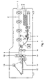
FIG. 1 is a schematic representation in side elevation of an exemplary inserting machine according to the invention; and
FIG. 2 is a schematic, cutaway representation in side elevation of a portion of the inserting machine according to FIG. 1 for opening the flap of an envelope.
DETAILED DESCRIPTION
The inserting machine according to the example represented in the drawing has an inlet 1 via which sheets, or sets each consisting of several sheets, can be supplied. From the inlet 1 extends a transport path 2 to a filling position 3 where envelopes can be filled in succession. A holder 4 for accommodating a supply 5 of envelopes to be filled is situated under the transport path 2. From the holder 4 extends a transport path 6, also to the filling position 3. The transport path extends through an assembly 7 for opening the flap 8 of an envelope 9 which has been supplied.
For discharging envelopes 9 from the filling position, a lowerable transport roller 10 is suspended above the filling position. Provisions for closing the flap of the envelope 9 comprise a lowered platform 12, situated behind a step 11, and a press-down roller 13, with which envelopes 9 can be pressed to the platform 12 and subsequently transported to a pair of sealing rollers 14 under the filling position 3. A moistener for moistening the gummed edge of the envelope is not represented for the sake of simplicity. Of the sealing rollers 14, the lower one is retractable. When the lower one of the sealing rollers 14 is retracted and the press-down roller 13 has been lifted off the envelope 9, this envelope 9 is released for transport in a direction transverse to the transport paths 2 and 6 by pairs of transport rollers 15, 16, which, prior to receiving the envelope 9 between them, are situated remote from each other, and for the purpose of discharging the envelope 9 are pressed towards each other and are driven.
The flap 8 of the envelope 9 is connected with a holder portion 18 of the envelope 9 along a fold edge 17. On a side remote from the fold edge 17, the flap 8 has a free edge 19. Prior to being opened, the flap 8 may to some extent be directed away from the holder portion 18 but in many cases it abuts as far as its free edge 19 against the holder portion 18.
The assembly for opening the flap 8 of the envelope 9 is equipped with circumferentially distributed scrapers 20, each having a sharp scraping end 21. In this example, an envelope carrier is formed by two sets of transport rollers 23, 24 and two guide plates 25, 26 upstream and downstream of the scrapers 20, on which rollers 23, 24 and plates 25, 26 the envelope 9 is supported.
A motor 27 is coupled to the transport rollers 23, 24 and is coupled, via a reverse clutch 29, to a roller 28, of which the scrapers 20 form a part. Thus, a drive is formed for moving the holder portion 18 and the scrapers 20 relative to each other, such that the holder portion 18, with the fold edge 17 in trailing position, scrapes along the scraping ends 21 for scraping at least a portion of the flap 8 remote from the fold edge 17 away from the holder portion 18. The scrapers 20 pivot the flap 8 in the area of its free edge 19 off the holder portion 18, so that the flap 8 pivots open about the fold edge 17.
Owing to the scrapers 20 being suspended and coupled to the drive 27, 29 for causing the scraping end 21 of the scrapers 20 to move in a circulation path 30, of which a first portion 31 extends in a direction towards the fold edge 17 over the holder portion 18 of the envelope 9 and a second, contiguous portion 32 diverges from the holder portion 18 of the envelope 9, the flap 8 is reliably scraped off the holder portion 18 and in an early stage actively pivoted away from the holder portion 18, so that the risk of damage of the envelope 9 in the area of the fold edge 17 is limited.
If the free edge of the flap 8 does not immediately engage one of the scrapers 20, there is at least a second chance of the next scraper 20 catching the flap 8. It is possible to provide just one scraper which is movable along a path in a circulation sense as described. According to this example, however, there are several of the scrapers 20 provided, spaced apart in a circulation sense and suspended for movement along the circulation path 30. This provides the advantage that the chance that the flap 8 is missed is further limited, in that at a given number of revolutions per unit time more scrapers are moved over the surface of the holder portion 18.
Owing to the circulation path 30 being a circular path about an axis 33 parallel to an envelope plane defined by the envelope carrying structure 23-26, the movement along the circulation path 30 is realized in a constructionally simple manner. What further promotes simplicity of construction is the scrapers 20 forming a toothed roller 28.
The scrapers 20 are then designed as teeth directed obliquely radially and tangentially in a circulation sense, so that they reliably engage the free edge 19 of the flap 8.
The circulation path 30 intersects an envelope plane 34 defined by the envelope carrying parts 23-26, for causing the envelope 9 to bend between the transport rollers 23, 24. As a result of this bending of the envelope 9, it is bent away from the flap 8, so that the free edge 19 of the flap 8 to some extent comes clear of the holder portion 18 of the envelope 9, and the scrapers 20 can engage the free edge 19 of the flap 8 with still greater reliability. Moreover, the circulating ends 21 of the scrapers 20, when they reach the bent envelope 9, tap against the envelope 9, which further promotes the flap 8 coming off the holder portion 18.
The inserting machine has an envelope transport detector 35 for determining when a leading edge of an envelope 9 that is being supplied has reached the path 30 of the scrapers 20. According to this example, this detector 35 is designed as a light-sensitive sensor responsive to interruption of light coming from an opposed light source. It is also possible, however, to detect the passage of the leading edge of an envelope in a different manner, for instance by recording the distance over which an envelope has moved since leaving the holder 4, based on angular displacements of an element of the transport drive.
The reverse clutch 29 and the detector 35 are coupled to a control 36 which is arranged for causing the scrapers 20, prior to the above-described movement in the circulation sense whereby the scraper ends move in a direction towards the fold edge 17 over the holder portion 18 of the envelope 9, to move in an opposite circulation sense, by rotating the roller 28 in the opposite sense. Further, the control 36 is arranged for reversing the circulation sense of the scrapers 20 by driving the clutch 29 for reversing the rotational direction of the roller 28, after the leading edge 37 of the envelope 9 passing in a direction 38 has passed the path of the scrapers 20. The scrapers 20 circulating in the opposite sense before the leading edge 37 of the envelope passes prevents their striking against the leading edge 37 of the envelope 9 being supplied. Consequently, it is not necessary to retract the scrapers 20 when the envelope 9 is being supplied, so that a robust and accurate suspension of the scrapers 20 is simple to realize.

Claims (10)

1. An inserting machine for inserting sheets into an envelope, comprising:
an assembly for unfolding a flap of an envelope, which flap is connected with a holder portion of the envelope along a fold edge, has a free edge on a side situated remote from the fold edge, and is folded as far as the flap's free edge against the holder portion;
means for transporting the envelope along a transport path which passes through the assembly, said transporting path including a plurality of supports for conveying the envelope along an envelope feed plane;
a drive for driving displacement of the holder portion along the envelope transport path with the fold edge of the envelope in a trailing position;
wherein the assembly includes:
a scraper roller including a plurality of scraper teeth for unfolding the flap, said scraper roller being rotatably provided between two of said supports and on an opposite side of the envelope feed plane from the two supports; and
a scraper drive for rotating the scraper roller in a forward direction in which the scraper teeth unfold the flap,
wherein each of the scraper teeth has an arcuate shape curving such that a sharp distal end is directed obliquely radially and tangentially in the forward direction,
wherein upon rotation, the distal ends of the teeth define a circulation path which intersect the envelope feed plane such that upon initial contact with the envelope, the distal ends of the scraper teeth apply pressure to the envelope to create a bend in the envelope between the two supports, whereupon at least one of the teeth scrapes the flap in the area of the free edge of the flap of the envelope off the holder portion that is displaced along the envelope transport path, and pivots the flap open about the fold edge.
2. An inserting machine according to claim 1, comprising a plurality of scrapers which are spaced apart in a circulation sense and are suspended for movement along the circulation path.
3. An inserting machine according to claim 2, wherein the scrapers form a toothed roller.
4. An inserting machine according to claim 1, wherein the circulation path is a circulation path about an axis parallel to an envelope plane defined by the envelope carrier.
5. An inserting machine for inserting sheets into an envelope, comprising an assembly for unfolding a flap of an envelope, which flap is connected with a holder portion of the envelope along a fold edge, has a free edge on a side situated remote from the fold edge, and is folded as far as the flap's free edge against the holder portion, comprising:
a scraper with a sharp scraping end and an envelope carrier, for scraping at least a portion of the flap remote from the fold edge off the holder portion;
a drive for moving the holder portion and the scraper relative to each other, such that the holder portion with the fold edge in trailing position scrapes along the scraping end, the scraper scrapes the flap in the area of its free edge off the holder portion, and pivots the flap open about the fold edge, wherein the scraper is suspended and coupled to a scraper drive for causing the scraping end to move along a circulation path, of which a first portion extends in a direction towards the fold edge over the holder portion of the envelope and of which a second, contiguous portion diverges from the holder portion of the envelope; and
an envelope transport detector for determining when a leading edge of the envelope, when being supplied, has passed the circulation path, wherein the scraper drive is coupled to a control for causing the scraper or scrapers, prior to the movement in the circulation sense whereby the scraper end or the scraper ends moves or move in a direction towards the fold edge over the holder portion of the envelope, to move in an opposite circulation sense, and for reversing the circulation sense of the scraper or scrapers after the leading edge of the envelope has passed the circulation path.
6. An inserting machine according to claim 5, comprising a plurality of scrapers which are spaced apart in a circulation sense and are suspended for movement along the circulation path.
7. An inserting machine according to claim 6, wherein the scrapers form a toothed roller.
8. An inserting machine according to claim 7, wherein the scrapers are designed as teeth directed obliquely radially and tangentially in a circulation sense.
9. An inserting machine according to claim 5, wherein the circulation path is a circulation path about an axis parallel to an envelope plane defined by the envelope carrier.
10. An inserting machine according to claim 5, wherein the circulation path intersects an envelope plane defined by the envelope carrier for causing the envelope to bend between supports.
US11/024,386 2003-12-31 2004-12-28 Machine and method for inserting sheets into envelopes Expired - Fee Related US7437862B2 (en)

Applications Claiming Priority (2)

Application Number Priority Date Filing Date Title
NL1025158 2003-12-31
NL1025158A NL1025158C2 (en) 2003-12-31 2003-12-31 Machine and method for embedding sheets.

Publications (2)

Publication Number Publication Date
US20050160703A1 US20050160703A1 (en) 2005-07-28
US7437862B2 true US7437862B2 (en) 2008-10-21

Family

ID=34651565

Family Applications (1)

Application Number Title Priority Date Filing Date
US11/024,386 Expired - Fee Related US7437862B2 (en) 2003-12-31 2004-12-28 Machine and method for inserting sheets into envelopes

Country Status (4)

Country Link
US (1) US7437862B2 (en)
EP (1) EP1559579B1 (en)
DE (1) DE602004029328D1 (en)
NL (1) NL1025158C2 (en)

Cited By (2)

* Cited by examiner, † Cited by third party
Publication number Priority date Publication date Assignee Title
US20090000254A1 (en) * 2004-10-01 2009-01-01 Gianfranco Passoni Method for Automatically Providing Covers for Compact Items, in Particular Documents, and Device Therefor
US20110099946A1 (en) * 2009-10-29 2011-05-05 Neopost Technologies Envelope inserting apparatus

Citations (32)

* Cited by examiner, † Cited by third party
Publication number Priority date Publication date Assignee Title
DE1009059B (en) 1954-10-11 1957-05-23 Frank Evans Boughton Inserting machine
US3162435A (en) 1962-09-05 1964-12-22 Pitney Bowes Inc Envelope flap conditioning apparatus
DE1461694A1 (en) 1963-10-28 1969-03-20 Standard Elek K Lorenz Ag Device for preparing envelopes to hold inserts
US3797196A (en) * 1972-12-04 1974-03-19 Pitney Bowes Inc Letter folder and envelope inserter
US3910007A (en) 1973-04-26 1975-10-07 Baeuerle Gmbh Mathias Device for opening the flaps of envelopes
US3996727A (en) * 1976-01-13 1976-12-14 Pitney-Bowes, Inc. Envelope flap separating mechanism
US4649691A (en) * 1986-01-27 1987-03-17 E. K. Mailing Machines Inc. Multiple rotary head collator and inserter
US4715164A (en) * 1986-02-28 1987-12-29 Pitney Bowes Inc. High speed envelope flap opener
US4813209A (en) 1988-04-29 1989-03-21 Pitney Bowes Inc. Single cycle envelope flap opener
US4852334A (en) 1988-09-12 1989-08-01 Pitney Bowes Inc. Envelope opening apparatus
US4903456A (en) 1987-11-26 1990-02-27 Smh Alcatel Device for controlling the advance and the positioning of envelopes in an insertion machine
US4909021A (en) * 1988-12-01 1990-03-20 Barbour William P Automatic envelope opener
EP0392867A1 (en) 1989-04-14 1990-10-17 BELL & HOWELL PHILLIPSBURG COMPANY In-line rotary inserter
US5251425A (en) * 1991-03-12 1993-10-12 Kern Ag Enveloping device
US5255498A (en) * 1990-11-02 1993-10-26 Pitney Bowes Inc. Envelope stuffing apparatus
JPH06166297A (en) * 1992-10-02 1994-06-14 Fuji Xerox Co Ltd Flap opening and feeding device for envelope, etc.
US5410860A (en) 1993-09-22 1995-05-02 Secap Inserting device for inserting documents into an envelope
US5415068A (en) * 1993-10-18 1995-05-16 Pitney Bowes Inc. Multi-function envelope feeder
WO1995016578A1 (en) 1993-12-15 1995-06-22 Secap Device for taking and opening envelopes from a pile
US5487254A (en) * 1990-01-25 1996-01-30 Printed Forms Equipment Limited Apparatus for inserting material into envelopes
US5511357A (en) * 1993-12-20 1996-04-30 Pitney Bowes Plc Apparatus for controlling the position of an envelope in an inserter machine
US5618375A (en) * 1992-11-11 1997-04-08 Juki Corporation Envelope processing unit
US5675959A (en) * 1996-01-18 1997-10-14 Pitney Bowes Inc. Opening fingers for envelope inserting apparatus
US5729954A (en) * 1996-09-04 1998-03-24 International Billing Services Envelope flap opener apparatus
US5802808A (en) 1997-07-17 1998-09-08 Pitney Bowes Inc. Envelope throat opening mechanism for inserting machine
US5809749A (en) 1996-10-21 1998-09-22 Bell & Howell Cope Company High speed envelope packing apparatus
US5867976A (en) 1997-08-01 1999-02-09 General Electric Company Self-retained borescope plug
US5950399A (en) * 1997-10-17 1999-09-14 Gunther International, Ltd. Apparatus and method for inserting a product into an envelope and closing same
US6036185A (en) 1995-11-17 2000-03-14 Secap System for unstacking and opening envelopes
US6199348B1 (en) 1996-10-21 2001-03-13 Bell & Howell Mail And Messaging Technologies Company High speed envelope packing apparatus
US6219647B1 (en) * 1996-06-04 2001-04-17 Hadewe, B.V. Method and an apparatus for preprocessing logging of received postal items
US6293076B1 (en) * 1999-09-29 2001-09-25 Pitney Bowes Inc. Method and apparatus for automatically positioning a pneumatic envelope opener

Family Cites Families (1)

* Cited by examiner, † Cited by third party
Publication number Priority date Publication date Assignee Title
US3797350A (en) * 1973-07-27 1974-03-19 Us Envelope Co Envelope opening apparatus

Patent Citations (32)

* Cited by examiner, † Cited by third party
Publication number Priority date Publication date Assignee Title
DE1009059B (en) 1954-10-11 1957-05-23 Frank Evans Boughton Inserting machine
US3162435A (en) 1962-09-05 1964-12-22 Pitney Bowes Inc Envelope flap conditioning apparatus
DE1461694A1 (en) 1963-10-28 1969-03-20 Standard Elek K Lorenz Ag Device for preparing envelopes to hold inserts
US3797196A (en) * 1972-12-04 1974-03-19 Pitney Bowes Inc Letter folder and envelope inserter
US3910007A (en) 1973-04-26 1975-10-07 Baeuerle Gmbh Mathias Device for opening the flaps of envelopes
US3996727A (en) * 1976-01-13 1976-12-14 Pitney-Bowes, Inc. Envelope flap separating mechanism
US4649691A (en) * 1986-01-27 1987-03-17 E. K. Mailing Machines Inc. Multiple rotary head collator and inserter
US4715164A (en) * 1986-02-28 1987-12-29 Pitney Bowes Inc. High speed envelope flap opener
US4903456A (en) 1987-11-26 1990-02-27 Smh Alcatel Device for controlling the advance and the positioning of envelopes in an insertion machine
US4813209A (en) 1988-04-29 1989-03-21 Pitney Bowes Inc. Single cycle envelope flap opener
US4852334A (en) 1988-09-12 1989-08-01 Pitney Bowes Inc. Envelope opening apparatus
US4909021A (en) * 1988-12-01 1990-03-20 Barbour William P Automatic envelope opener
EP0392867A1 (en) 1989-04-14 1990-10-17 BELL & HOWELL PHILLIPSBURG COMPANY In-line rotary inserter
US5487254A (en) * 1990-01-25 1996-01-30 Printed Forms Equipment Limited Apparatus for inserting material into envelopes
US5255498A (en) * 1990-11-02 1993-10-26 Pitney Bowes Inc. Envelope stuffing apparatus
US5251425A (en) * 1991-03-12 1993-10-12 Kern Ag Enveloping device
JPH06166297A (en) * 1992-10-02 1994-06-14 Fuji Xerox Co Ltd Flap opening and feeding device for envelope, etc.
US5618375A (en) * 1992-11-11 1997-04-08 Juki Corporation Envelope processing unit
US5410860A (en) 1993-09-22 1995-05-02 Secap Inserting device for inserting documents into an envelope
US5415068A (en) * 1993-10-18 1995-05-16 Pitney Bowes Inc. Multi-function envelope feeder
WO1995016578A1 (en) 1993-12-15 1995-06-22 Secap Device for taking and opening envelopes from a pile
US5511357A (en) * 1993-12-20 1996-04-30 Pitney Bowes Plc Apparatus for controlling the position of an envelope in an inserter machine
US6036185A (en) 1995-11-17 2000-03-14 Secap System for unstacking and opening envelopes
US5675959A (en) * 1996-01-18 1997-10-14 Pitney Bowes Inc. Opening fingers for envelope inserting apparatus
US6219647B1 (en) * 1996-06-04 2001-04-17 Hadewe, B.V. Method and an apparatus for preprocessing logging of received postal items
US5729954A (en) * 1996-09-04 1998-03-24 International Billing Services Envelope flap opener apparatus
US5809749A (en) 1996-10-21 1998-09-22 Bell & Howell Cope Company High speed envelope packing apparatus
US6199348B1 (en) 1996-10-21 2001-03-13 Bell & Howell Mail And Messaging Technologies Company High speed envelope packing apparatus
US5802808A (en) 1997-07-17 1998-09-08 Pitney Bowes Inc. Envelope throat opening mechanism for inserting machine
US5867976A (en) 1997-08-01 1999-02-09 General Electric Company Self-retained borescope plug
US5950399A (en) * 1997-10-17 1999-09-14 Gunther International, Ltd. Apparatus and method for inserting a product into an envelope and closing same
US6293076B1 (en) * 1999-09-29 2001-09-25 Pitney Bowes Inc. Method and apparatus for automatically positioning a pneumatic envelope opener

Cited By (4)

* Cited by examiner, † Cited by third party
Publication number Priority date Publication date Assignee Title
US20090000254A1 (en) * 2004-10-01 2009-01-01 Gianfranco Passoni Method for Automatically Providing Covers for Compact Items, in Particular Documents, and Device Therefor
US8590280B2 (en) * 2004-10-01 2013-11-26 Bowe Systec Gmbh Method and apparatus for inserting objects into opened envelopes
US20110099946A1 (en) * 2009-10-29 2011-05-05 Neopost Technologies Envelope inserting apparatus
US9150046B2 (en) * 2009-10-29 2015-10-06 Neopost Technologies Envelope inserting apparatus

Also Published As

Publication number Publication date
US20050160703A1 (en) 2005-07-28
NL1025158C2 (en) 2005-07-04
DE602004029328D1 (en) 2010-11-11
EP1559579B1 (en) 2010-09-29
EP1559579A1 (en) 2005-08-03

Similar Documents

Publication Publication Date Title
SE461269B (en) SEAT AND DEVICE FOR COLLECTION OF FALLED PRINT SHEETS
US4169341A (en) Document collating and envelope stuffing apparatus
NL7904441A (en) DEVICE FOR THE ROAD TRANSPORTATION OF LANDING FLAT PRODUCTS, IN PARTICULAR PRINTED PRODUCTS.
AU2008297642B2 (en) Winding device and assembly comprising a winding device
JP5657931B2 (en) Method and apparatus for forming and applying a folded flyer
US4715594A (en) Face and back reversing mechanism
GB2153790A (en) Mail sorting machine
US7437862B2 (en) Machine and method for inserting sheets into envelopes
EP0781671B1 (en) Apparatus and method for inserting documents into envelopes
SE466600B (en) SETTING AND DEVICE FOR PROCESSING OF PRINTED PRODUCTS
US5556087A (en) Apparatus for processing printed products
US4105197A (en) Apparatus for folding collapsible box blanks
FI82020B (en) ANORDNING FOER SAMLING AV VIKTA TRYCKARK.
JPH10513427A (en) Apparatus for separating one or more rotationally symmetric containers from a stream of rotationally symmetric containers conveyed under line pressure and a cylinder with a piston which can be extended in a controlled manner
EP1552960A2 (en) Mail processing machine
US20060144016A1 (en) Apparatus for inserting documents into envelopes
US5711521A (en) Conveying apparatus for printed products
DE03710077T1 (en) Wrapping
US3426882A (en) Board turning apparatus
US11827474B2 (en) Accumulator for processing line and method of using same
EP1870252A2 (en) Envelope flap closing system
US5992840A (en) Apparatus for processing sheet-like products
US5867967A (en) Envelope flap opening device
JP4744340B2 (en) Paper bundle positioning device with function to detect paper bundle irregularity
EP0703097A1 (en) Method and apparatus for opening an envelope

Legal Events

Date Code Title Description
AS Assignment

Owner name: NEOPOST S.A., FRANCE

Free format text: ASSIGNMENT OF ASSIGNORS INTEREST;ASSIGNOR:VAN DER WERFF, JEICHIENUS ADRIAAN;REEL/FRAME:016445/0271

Effective date: 20050307

STCF Information on status: patent grant

Free format text: PATENTED CASE

FPAY Fee payment

Year of fee payment: 4

FPAY Fee payment

Year of fee payment: 8

FEPP Fee payment procedure

Free format text: MAINTENANCE FEE REMINDER MAILED (ORIGINAL EVENT CODE: REM.); ENTITY STATUS OF PATENT OWNER: LARGE ENTITY

LAPS Lapse for failure to pay maintenance fees

Free format text: PATENT EXPIRED FOR FAILURE TO PAY MAINTENANCE FEES (ORIGINAL EVENT CODE: EXP.); ENTITY STATUS OF PATENT OWNER: LARGE ENTITY

STCH Information on status: patent discontinuation

Free format text: PATENT EXPIRED DUE TO NONPAYMENT OF MAINTENANCE FEES UNDER 37 CFR 1.362

FP Lapsed due to failure to pay maintenance fee

Effective date: 20201021